Downloaded 223 times


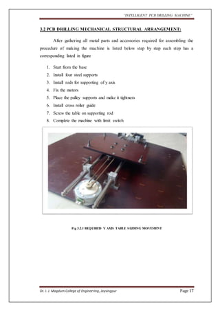


![“INTELLIGENT PCB DRILLING MACHINE”
7.1 RS232 STANDARDS
RS232: DB9 Connector:
In telecommunications, RS-232 is a standard for serial binary data
interconnection between a DTE (Data terminal equipment) and a DCE (Data Circuit-terminating
Equipment). It is commonly used in computer serial ports.
Scope of the Standard:
The Electronic Industries Alliance (EIA) standard RS-232-C [3] as of 1969 defines:
Electrical signal characteristics such as voltage levels, signaling rate, timing
and slew-rate of signals, voltage withstand level, short-circuit behavior,
maximum stray capacitance and cable length
Interface mechanical characteristics, pluggable connectors and pin
identification
Functions of each circuit in the interface connector
Standard subsets of interface circuits for selected telecom applications
Dr. J. J. Magdum College of Engineering, Jaysingpur Page 42](https://image.slidesharecdn.com/intelligentpcbdrillingmachine-141123024241-conversion-gate02/85/Intelligent-pcb-drilling-machine-42-320.jpg)


![“INTELLIGENT PCB DRILLING MACHINE”
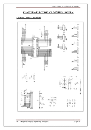
Operational Overview:
1] Busy Flag (BF)
When the busy flag is HIGH level, it indicates that the controller is in the internal
operation mode and the next instruction will not be accepted. When R/W is ‘1’ and
RS is ‘0’ the busy flag is output from DB. The next instruction must be written after
the busy flag goes low.
2] Address Counter (AC)
The address counter (AC) generates the address for the DD RAM, the CG
RAM and for the cursor display. When an instruction code for DD or CG RAM
address is written to the controller, after deciding whether it is DD RAM or CG RAM,
the address information is transferred to AC. After writing into (or reading from) DD
or CG RAM display data, AC is automatically incremented (decremented). The data
of the AC is output to DB0-DB6 when RS is ‘0’ and R/W is ‘1’.
3] Character Generator ROM (CG ROM)
The character generator ROM generates 5 x 7 dot or 5 x 10 dot character patterns
from 8- bit character codes. It can generate 160 types of 5 x 7 dot character patterns
and 32 types of 5 x 10 dot character patterns. When the 8-bit character code of a CG
ROM is written to the DD RAM, the character pattern of the CG ROM corresponding
to the code is displayed on the LCD display position corresponding to the DD RAM.
Dr. J. J. Magdum College of Engineering, Jaysingpur Page 51](https://image.slidesharecdn.com/intelligentpcbdrillingmachine-141123024241-conversion-gate02/85/Intelligent-pcb-drilling-machine-51-320.jpg)
![“INTELLIGENT PCB DRILLING MACHINE”
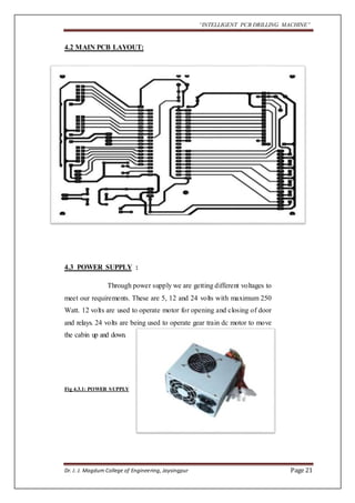
4] Character Generator RAM (CG RAM)
The character generator RAM (CG RAM) is the RAM with which the user can
generate character patterns by program. The CG RAM has the capacity to store 8
kinds of 5 x 7 dots or 4 kinds of 5 x 10 dots. Programming of these character patterns
is explained in CG RAM programming.
5] Display Data RAM (DD RAM)
The display data RAM (DD RAM) stores display data represented in 8-bit
(hexadecimal) character codes. Its capacity is 80 x 8 bits, or 80 characters. The
display data RAM (DD RAM) that is not used for display can be used as general data
RAM. Depending on the 8- bit character code that is written into the DD RAM. LCD
will select the character pattern either from Character Generator RAM (CG RAM) or
from Character Generator ROM (CG ROM).
6] Underline/Blinking Block Cursor
Cursor is under the control of the MPU Programmed. The display of the cursor on the
LCD is made at a position corresponding to the DD RAM address set to the address
counter (AC).
Dr. J. J. Magdum College of Engineering, Jaysingpur Page 52](https://image.slidesharecdn.com/intelligentpcbdrillingmachine-141123024241-conversion-gate02/85/Intelligent-pcb-drilling-machine-52-320.jpg)


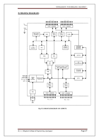
The document outlines a project aimed at developing an intelligent PCB drilling machine, designed to automate and improve the drilling process of printed circuit boards (PCBs) to reduce time and labor. Historical context is provided on the conventional PCB drilling methods and their drawbacks, such as inaccuracies and dependency on human skills. The proposed system integrates software and hardware components, including microcontrollers and stepper motors, to enhance precision and efficiency in PCB manufacturing.


