Download to read offline
![IEEE ANTENNAS AND WIRELESS PROPAGATION LETTERS, VOL. 18, NO. 4, APRIL 2019 747
A MIMO Dielectric Resonator Antenna With
Improved Isolation for 5G mm-Wave Applications
Yin Zhang, Jing-Ya Deng , Member, IEEE, Ming-Jie Li, Dongquan Sun , Member, IEEE,
and Li-Xin Guo, Senior Member, IEEE
Abstract—A multiple-input–multiple-output dielectric res-
onator antenna with enhanced isolation is proposed in this letter for
the future 5G millimeter (mm)-wave applications. Two rectangular
dielectric resonators (DRs) are mounted on a substrate excited by
rectangular microstrip-fed slots underneath DRs. Each DR has a
metal strip printed on its upper surface moving the strongest part
of the coupling field away from the exciting slot to improve the isola-
tion between two antenna elements. The proposed antenna obtains
a simulated impedance bandwidth (S11 ࣘ –10 dB) from 27.25 to
28.59 GHz, which covers the 28 GHz band (27.5–28.35 GHz) al-
located by the Federal Communications Commission for the 5G
applications. A maximum improvement of 12 dB on the isolation
over 27.5–28.35 GHz is achieved. The mechanism of the isolation
improvement and the design procedure are given in this letter. A
prototype is manufactured and measured as a validation of the
proposed decoupling method.
Index Terms—5G communication, decouple, dielectric resonator
antenna (DRA), multiple-input–multiple-output (MIMO).
I. INTRODUCTION
OVER the past few decades, the mobile communication
technology has developed rapidly. As the next-generation
mobile communication technology after 4G, 5G needs to meet
the increasing demands of the people’s mobile communication,
which has become one of the hot research issues of concern in the
academic domain. As a result, more and more attention has been
paid on millimeter (mm)-wave and submillimeter-wave bands
due to their large sequential bandwidth. There are several kinds
of antennas that can be utilized for 5G mm-wave applications,
such as microstrip antenna [1] and its array [2]. However, the
decrease in radiation efficiency occurs due to the considerable
metallic and surface wave loss at mm-wave frequencies.
A dielectric resonator antenna (DRA) was first proposed in
the early 1980s [3]. A dielectric resonator (DR) is utilized as
the radiating structure, thus there is no ohmic loss of DRA.
The development of the processing technology of the high-
dielectric-constant dielectric material can reduce the dielectric
loss of the DRA to a very low level. Therefore, the DRA can
maintain high radiation efficiency in the millimeter-wave band.
Manuscript received January 22, 2019; accepted February 23, 2019. Date
of publication February 27, 2019; date of current version April 5, 2019. This
work was supported in part by the Natural Science Foundation of China under
Grant 61471280 and Grant 61871457; in part by the Key R&D Plan of Shaanxi
Province under Grant 2017ZDCXL-GY-04-01; and in part by the 111 Project
under Grant B17035. (Corresponding author: Jing-Ya Deng.)
The authors are with the School of Physics and Optoelectronic En-
gineering, Xidian University, Xi’an 710071, China (e-mail:, iszhangyin@
163.com; jydeng@xidian.edu.cn; mjlixidian@163.com; dqsun87@163.com;
lxguo@xidian.edu.cn).
Digital Object Identifier 10.1109/LAWP.2019.2901961
The multiple-input–multiple-output (MIMO) technology can in-
crease the system channel capacity notably and show obvious
advantages without increasing spectrum resources and antenna
transmission power [4]. High isolations between antenna ele-
ments are required in MIMO systems. A lot of technologies
have been introduced on improving the isolations of MIMO
DRAs, such as hybrid feeding mechanism generating orthog-
onal modes [5]–[8] and parasitic structures including metallic
entities [9], metasurface shields [10], and frequency selective
surfaces (FSSs) [11] to block the displacement current between
antenna elements. A systematic method based on degeneration
mode theory to improve the isolation of MIMO DRA was pre-
sented in [5] producing two orthogonal modes with the same
resonant frequencies. The isolation between the two ports is
enhanced to 40 dB by making a TE011+δ mode and an HE11δ
mode resonate at the same frequency. The typical application of
parasitic structures for improvement on the isolation is reported
in [10]. By loading the DRA with 1 × 7 array of split-ring res-
onator unit cells, a 28 dB improvement on the isolation level is
obtained without compromising the antenna performance.
In this letter, a method to improve the isolation between two
adjacent DRA elements is proposed. By introducing a metal strip
printed on the upper surface of each DR, the strongest part of the
coupling field moves away from the adjacent exciting slot of the
DRA so that a maximum improvement of 12 dB on the isolation
over 27.5–28.35 GHz is achieved. The reflection coefficient
of the proposed MIMO DRA with metal strips is less than –
10 dB over 27.25–28.59 GHz, showing that the introduction of
metal strips does not affect the impedance matching of DRA
significantly.
Section II illustrates the design procedure and the mechanism
of how metal strips enhance the isolation between two elements
of the proposed MIMO DRA. In Section III, experimental results
and discussions are carried out as a validation to simulated
results. Finally, a conclusion is arrived at in Section IV.
II. ANTENNA GEOMETRY AND DESIGN
The geometry and dimensions of the proposed MIMO DRA
with enhanced isolation for 5G mm-wave application are shown
in Fig. 1 and Table I, respectively. Two rectangular DRs with
relative permittivity of 9.8 are mounted on the Rogers 5880 sub-
strate with εr of 2.2, tanδ of 0.0009, and thickness of 0.254 mm.
A microstrip-fed rectangular exciting slot is set underneath each
DR for excitation purpose. A metal strip with length of Lp and
width of Wp is printed on the upper surface of each DR to en-
hance the isolation between two antenna elements. The detailed
design process of the proposed MIMO DRA is illustrated as
follows.
1536-1225 © 2019 IEEE. Personal use is permitted, but republication/redistribution requires IEEE permission.
See http://www.ieee.org/publications standards/publications/rights/index.html for more information.](https://image.slidesharecdn.com/mimo-200124055321/75/Mimo-1-2048.jpg)
![748 IEEE ANTENNAS AND WIRELESS PROPAGATION LETTERS, VOL. 18, NO. 4, APRIL 2019
Fig. 1. Geometry structure of the proposed MIMO DRA. (a) Exploded 3-D
view. (b) Top view.
TABLE I
GEOMETRIC PARAMETERS OF THE MIMO DRA. UNITS: mm
A. MIMO DRA Design
Two identical DRs with the dimension a × b × d are mounted
on the metal ground plane with the dimension of 20 mm ×
20 mm. The TEy
311 mode is excited by a microstrip-fed rectan-
gular slot. The resonant frequency of a rectangular DR for the
TEy
pqr mode can be derived from the wavenumbers kx, ky , and
kz inside the DR, and the subscripts p, q, and r are numbers of
the standing waves along the x-axis, y-axis, and z-axis, respec-
tively. The wavenumbers can be calculated using the Marcatili’s
approximation method [12]. The dimension of the DR can be
set to a = 9.5 mm, b = 7.5 mm, and d = 2.54 mm, which
makes the DR resonate at 28 GHz for the TEy
311 mode cal-
culated using the Marcatili’s approximation method mentioned
above.
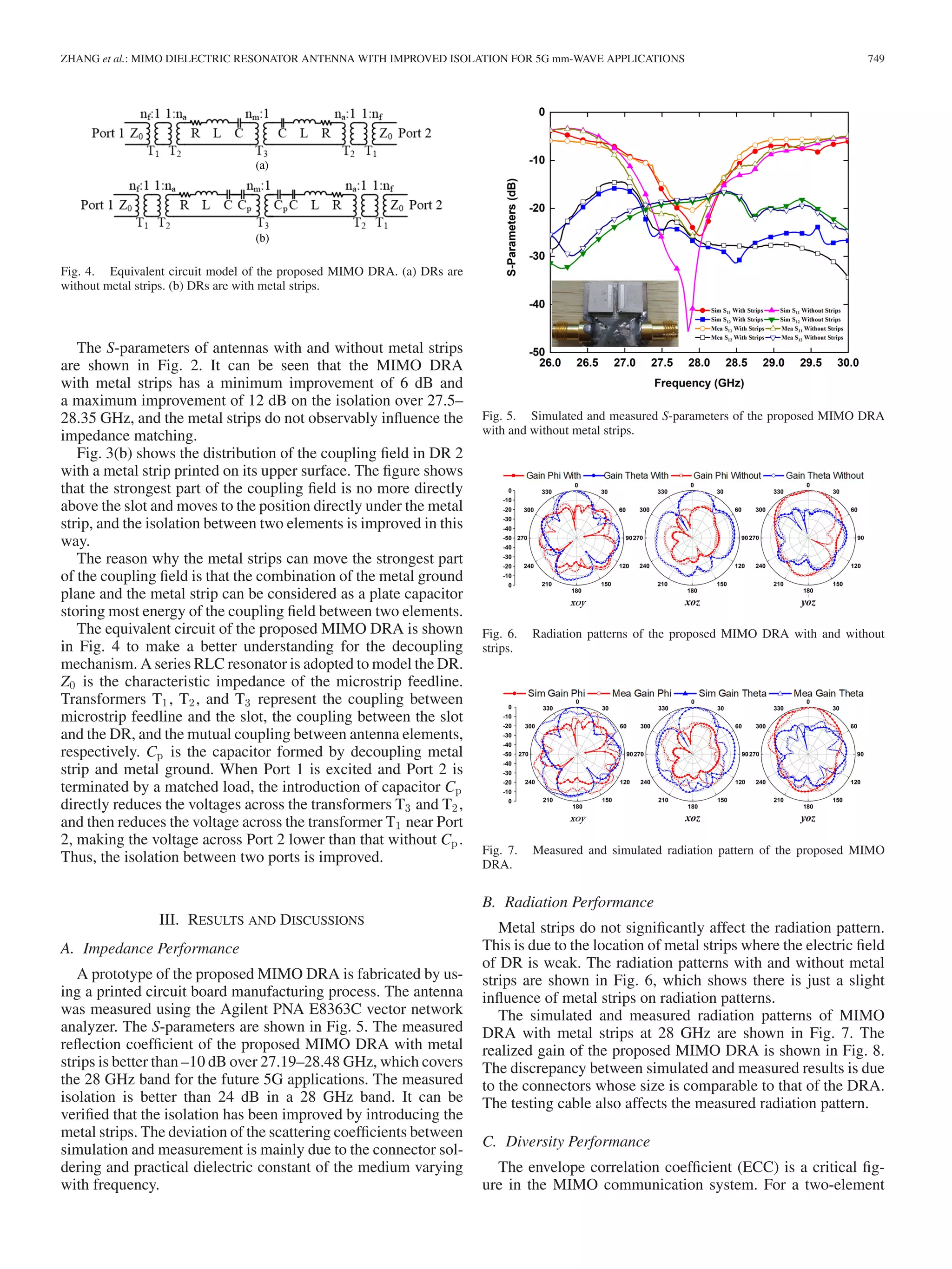
Fig. 2. Simulated S-parameters of the DRA with and without strips.
Fig. 3. Amplitude distribution of the coupling field (only Port 1 is excited).
(a) DRs are without metal strips. (b) DRs are with metal strips.
The MIMO DRA without metal strips is simulated by us-
ing the Ansys HFSS software. The simulated S-parameters are
shown in Fig. 2. It can be seen that the S11 is better than –10 dB
over 27.00–28.83 GHz, and that the S12 is around –17 dB in a
28 GHz band. The isolation should be improved further to meet
the requirement of a higher diversity gain.
B. High-Isolation Design
A metal strip is introduced and printed on the upper surface of
each DR to improve the isolation between two antenna elements.
To investigate why the metal strips can significantly improve the
isolation, the distribution of the coupling electrical field above
the exciting slot of DR 2 with and without the metal strips are
simulated and compared in Fig. 3 when only Port 1 is fed.
It can be observed in Fig. 3 that the strongest part of the cou-
pling field is directly above the microstrip-fed rectangular slot.
Therefore, the energy of the coupling field can be transmitted to
Port 2 via the slot resulting in strong coupling.](https://image.slidesharecdn.com/mimo-200124055321/75/Mimo-2-2048.jpg)
![750 IEEE ANTENNAS AND WIRELESS PROPAGATION LETTERS, VOL. 18, NO. 4, APRIL 2019
Fig. 8. Realized gain and ECC of the proposed MIMO DRA.
Fig. 9. Channel capacity of the proposed MIMO DRA.
MIMO antenna, the ECC can be calculated according to radia-
tion patterns. The ECC of the proposed MIMO DRA is lower
than 0.013 in a 28 GHz band as shown in Fig. 8, which con-
tributes to a large channel capacity and diversity gain of the
MIMO communication system.
The diversity gain is another critical parameter for evaluating
the MIMO system performance. It can be obtained by [13]
DG = 10 1 − ECC2 (1)
where 10 is the maximum apparent diversity gain at the 1%
probability level for selection combining. Since ECC of the
proposed MIMO DRA is less than 0.013, the diversity gain is
more than 9.9 dB.
The channel capacity can be calculated by the following equa-
tion [14]:
C = log2 I − SH
R SR I − SH
T ST γ /2 − 1.18 (2)
where { }H
denotes the Hermitian transposition, γ is the
signal-to-noise ratio at the receiving antenna, I is an identity ma-
trix, and SR and SH are S-matrices of transmitting and receiving
antennas, respectively. The channel capacity of the proposed
MIMO DRA is shown in Fig. 9.
Fig. 10. TARC of the proposed MIMO DRA with θ varying.
TABLE II
COMPARISON WITH OTHER WORKS
A total active reflection coefficient (TARC) is presented for
multiport systems [15], which takes into consideration the effect
when ports of the multiple-antenna system are fed with signals
of different phases and can be obtained by
Γt
a = |S11 + S12ejθ |
2
+ |S21 + S22ejθ |
2
/2 (3)
where θ is the phase difference between two feeding ports. The
TARC of the proposed MIMO DRA is shown in Fig. 10. It
can be noticed that the TARC always covers a 28 GHz band in
the variation of the θ and follows the original behavior of the
antenna characteristics.
The comparisons of the proposed MIMO DRA with other
related works are listed in Table II. It can be seen that the de-
coupling structure of the proposed MIMO DRA has the small-
est size and that a lower ECC and a higher isolation are ob-
tained.
IV. CONCLUSION
In this letter, a MIMO DRA with enhanced isolation for the
future 5G mm-wave applications is designed, analyzed, and
measured. The isolation of the proposed antenna is improved
to 24 dB by introducing a metal strip printed on the upper
surface of each DR moving the strongest part of the coupling
field away from the exciting slot. A maximum improvement of
12 dB on the isolation over 27.5–28.35 GHz is achieved in this
way. The MIMO DRA is simulated, fabricated, and measured.
The simulated and measured results are with a good agreement,
showing the validity of the proposed decoupling technology.](https://image.slidesharecdn.com/mimo-200124055321/75/Mimo-4-2048.jpg)
![ZHANG et al.: MIMO DIELECTRIC RESONATOR ANTENNA WITH IMPROVED ISOLATION FOR 5G mm-WAVE APPLICATIONS 751
REFERENCES
[1] J. Kornprobst, K. Wang, G. Hamberger, and T. F. Eibert, “A mm-wave
patch antenna with broad bandwidth and a wide angular range,” IEEE
Trans. Antennas Propag., vol. 65, no. 8, pp. 4293–4298, Aug. 2017.
[2] C. Mao, S. Gao, and Y. Wang, “Broadband high-gain beam-scanning
antenna array for millimeter-wave applications,” IEEE Trans. Antennas
Propag., vol. 65, no. 9, pp. 4864–4868, Sep. 2017.
[3] S. Long, M. McAllister, and S. Liang, “The resonant cylindrical dielec-
tric cavity antenna,” IEEE Trans. Antennas Propag., vol. AP-31, no. 3,
pp. 406–412, May 1983.
[4] A. J. Paulraj, D. A. Gore, R. U. Nabar, and H. Bolcskei, “An overview of
MIMO communications - A key to gigabit wireless,” Proc. IEEE, vol. 92,
no. 2, pp. 198–218, Feb. 2004.
[5] J. Yan and J. T. Bernhard, “Design of a MIMO dielectric resonator antenna
for LTE femtocell base stations,” IEEE Trans. Antennas Propag., vol. 60,
no. 2, pp. 438–444, Feb. 2012.
[6] L. Zou, D. Abbott, and C. Fumeaux, “Omnidirectional cylindrical dielec-
tric resonator antenna with dual polarization,” IEEE Antennas Wireless
Propag. Lett., vol. 11, pp. 515–518, 2012.
[7] H. Yan, L. Taolin, D. Xiangyu, and W. Weiwei, “The design of a tripo-
larization rectangle dielectric resonator antenna,” in Proc. 10th Eur. Conf.
Antennas Propag., 2016, pp. 1–3.
[8] A. Abdalrazik, A. S. A. El-Hameed, and A. B. Abdel-Rahman, “A three-
port MIMO dielectric resonator antenna using decoupled modes,” IEEE
Antennas Wireless Propag. Lett., vol. 16, pp. 3104–3107, 2017.
[9] M. S. Sharawi, S. K. Podilchak, M. U. Khan, and Y. M. Antar, “Dual-
frequency DRA-based MIMO antenna system for wireless access points,”
Microw., Antennas Propag., vol. 11, no. 8, pp. 1174–1182, 2017.
[10] A. Dadgarpour, B. Zarghooni, B. S. Virdee, T. A. Denidni, and A. A.
Kishk, “Mutual coupling reduction in dielectric resonator antennas using
metasurface shield for 60 GHz MIMO systems,” IEEE Antennas Wireless
Propag. Lett., vol. 16, pp. 477–480, 2017.
[11] R. Karimian, A. Kesavan, M. Nedil, and T. A. Denidni, “Low-mutual-
coupling 60 GHz MIMO antenna system with frequency selective sur-
face wall,” IEEE Antennas Wireless Propag. Lett., vol. 16, pp. 373–376,
2017.
[12] R. K. Mongia, “Theoretical and experimental resonant frequencies of rect-
angular dielectric resonators,” IEE Proc. H, – Microw. Antennas Propag.,
vol. 139, no. 1, pp. 98–104, 1992.
[13] Y. Gao, X. Chen, Z. Ying, and C. Parini, “Design and performance in-
vestigation of a dual-element PIFA array at 2.5 GHz for MIMO termi-
nal,” IEEE Trans. Antennas Propag., vol. 55, no. 12, pp. 3433–3441,
Dec. 2007.
[14] N. Honma, H. Sato, K. Ogawa, and Y. Tsunekawa, “Accuracy of MIMO
Channel capacity equation based only on S-parameters of MIMO an-
tenna,” IEEE Antennas Wireless Propag. Lett., vol. 14, pp. 1250–1253,
2015.
[15] M. Manteghi and Y. Rahmat-Samii, “Multiport characteristics of a wide-
band cavity backed annular patch antenna for multipolarization opera-
tions,” IEEE Trans. Antennas Propag., vol. 53, no. 1, pp. 466–474, Jan.
2005.](https://image.slidesharecdn.com/mimo-200124055321/75/Mimo-5-2048.jpg)

This document summarizes a research paper that proposes a multiple-input multiple-output (MIMO) dielectric resonator antenna (DRA) design with improved isolation for 5G millimeter-wave applications. The design uses two rectangular DRs excited by microstrip slots underneath, with a metal strip printed on each DR to move the strongest part of the coupling field away from the slot, improving isolation between elements. Simulations show the design achieves over 12 dB improved isolation across 27.5-28.35 GHz while maintaining impedance bandwidth. A prototype was fabricated and measured, validating over 24 dB isolation in the 28 GHz band.


![Seller Deck - Presentation [Concert L2].PPTX](https://cdn.slidesharecdn.com/ss_thumbnails/sellerdeck-presentationconcertl2-251219171156-24982daf-thumbnail.jpg?width=640&height=640&fit=bounds)


