This document describes the design and testing of a dual-polarized slot array patch antenna for WiMAX applications operating at 5.8 GHz. The antenna consists of an 8x8 array of circular patch elements, with each element excited using an aperture coupled microstrip feed. The design was optimized using simulation software to achieve high gain (26 dBi), wide bandwidth (14%), high port isolation, and good radiation patterns. Both simulated and measured results showed good agreement. The antenna meets specifications for WiMAX applications in the 5.15-5.9 GHz band and was found to be low-cost and easy to fabricate.
Gain Enhancement of Series Feed Square Patch Microstrip Antenna Array for S b...ijsrd.com
Gain is the ability of an antenna to concentrate the radiated power in a desired direction. Only small gain can be achieved by single antenna that is why, antenna arrays are required to improve the gain by using different feed networks. This paper describes the design and performance of a series feed antenna array. The operating frequency of 2.4GHz is used. The aim of this paper is to improve the gain of a series feed antenna array. Line feed is used for designing single antenna, 2x1 & 4x1 microstrip antenna array. These series feed microstrip antenna arrays are useful for both S and C band. The proposed antenna is simulated by IE3D version 9.0 Zealand simulation software based on method of moments.
EFFECT OF DIFFERENT SYMMETRIC SLITS ON MICROSTRIP PATCH ANTENNAjmicro
In this paper, a basic linearly polarised microstrip square patch antenna operating at 2.4 GHz is
proposed. We have modified the basic microstrip square patch antenna with rectangular shape slits, V
shape slits and truncated corners to achieve circular polarization. Basically we have designed five
different antennas to meet the specification. The various antennas have been simulated, fabricated and the
performance has been tested on network analyser (Agilent Technologies: N9912A, SNMY51464189,
ROHDE & SCHWARZ: ZVL13, 9 KHz to 13.6GHz,). The simulated and tested performance shows close
agreement with each other. The various structures used in this study are microstrip square patch radiator,
microstrip square patch radiator with truncated corner, rectangular slits, truncated corner with
rectangular slits and V shape slits. The experiment results show rectangular slits with truncated corners in
the main square patch and rectangular slits in the main square patch provide better performance with
respect to the antenna parameters. Designed antenna is compact and provides circular polarization at the
required operating frequency of 2.4GHz with improved bandwidth and gain. The use of circularly
polarized antennas presents an attractive solution to achieve this polarization match which allows for
more flexibility in the angle between transmitting and receiving antennas. It gives the following
advantages such as reduction in the effect of multipath reflections, decrease in transmission losses,
enhancement of weather penetration and allowing any orientation to the communication system
DESIGN AND DEVELOPMENT OF ITERATIVE SQUARE RING FRACTAL ANTENNA FOR DUAL BAND...jmicro
In this paper, iterative square ring fractal antenna is proposed, designed and developed for Wireless
application. The functional characteristics of the antenna such as return loss, VSWR, radiation pattern and
gain are evaluated. Compact size and multi-band compatibility are the major design requirements of
fractal antenna. The proposed antenna has the dimension of 20mm X 20mm and it supports dual band
which is designed in FR4 substrate. It resonates at 5.9 GHz and 8.8 GHz with the return loss of -33dB, -
16dB, respectively. Further, the performance of the antenna is analyzed by varying feed position, feed
width and substrate thickness. By the analysis, we concluded that the proposed antenna have better
performance at left feed position with 0.9mm of feed width at the substrate thickness of 3.2mm.
In this paper, variations in the capacitive fed suspended RMSA configurations have been proposed. Initially, the reference antenna consists of rectangular patch of size of (35.5 X 45.6) mm2 and a small rectangular feed patch of size of (1.4 X 4) mm2 residing on the same substrate suspended above the ground plane. Coaxial probe is used to feed the small patch which in turn excites the radiator patch electromagnetically, yielding a large impedance bandwidth (BW) of 39%, with good gain and broadside radiation pattern. By, meandering the ground plane of reference antenna with three rectangular slots, the prototype antenna is fabricated and measurement has been carried out to validate the result for compact broadband response. Later, by loading a pair of rectangular slots in the radiating patch of the reference antenna in addition to the rectangular slots in the ground plane, the prototype antenna is fabricated and measurement has been carried out to validate the result for compact dual band response.
International Journal of Engineering Research and Applications (IJERA) is an open access online peer reviewed international journal that publishes research and review articles in the fields of Computer Science, Neural Networks, Electrical Engineering, Software Engineering, Information Technology, Mechanical Engineering, Chemical Engineering, Plastic Engineering, Food Technology, Textile Engineering, Nano Technology & science, Power Electronics, Electronics & Communication Engineering, Computational mathematics, Image processing, Civil Engineering, Structural Engineering, Environmental Engineering, VLSI Testing & Low Power VLSI Design etc.
Compact Quad-band Antenna for WiMax Applicationijsrd.com
A single feed quad band compact rectangular microstrip antenna for Wi-max applications has been designed and developed. This antenna is incorporated by one c-shaped slot, one L-shaped slot & two I-shaped slot structure along the length on the patch. Four resonating frequencies are obtained at 2.5 GHz with return loss -25.01 dB, 3.5 GHz with return loss -17.9 dB, 4.9 GHz with return loss -25.74 dB and 5.8 GHz with return loss -28.32 dB. The size of the antenna has been reduced by 77.3% when compared to a conventional microstrip patch without slot. An extensive analysis of the return loss, radiation pattern and efficiency of the proposed antenna has been given in this paper. The characteristics of the designed structure is simulated by High frequency structure simulator (HFSS) software and implemented using RT DUROID dielectric substrate which has ϵr = 2.2 and h = 1.575mm. The proposed antenna leads to multi frequency operation makes it suitable for Wireless Communication applications.
Design and Analysis of Microstrip Patch Antenna with Optimization for Wireles...ijsrd.com
In this paper, design of conventional Rectangular patch Microstrip antenna has been proposed and its performance is analyzed. The design parameters of antenna are selected to achieve compact dimensions as well as best possible characteristics such as high gain, increased bandwidth with minimum return loss. Hence improved design has been demonstrated over elementary one. These antennas have been designed at 2.4GHz which enables its usage in wireless communication domain such as Wireless Local Area Network (WLAN). The antenna design and performance are analyzed using Ansoft HFSS software. These antennas can be used for many wireless communication systems.
Circularly polarized antenna array based on hybrid couplers for 5G devicesjournalBEEI
This paper depicts a wideband circularly polarized (CP) antenna for 5G devices. The antenna array has a 3D structure including four simple printed dipole elements with directional radiations, high gain, and high efficiency. It achieves a CP by using the sequential rotation (SR) feeding based on 90°-3dB hybrid couplers in the proposed feeding network. The antenna array bandwidth is wide, 26.7%, with an operating frequency band from 3.35 GHz to 4.35 GHz. The antenna achieves a high peak gain of 10.73 dBi and high efficiency of 93.75%. Besides, the antenna gain is stable over the operating bandwidth (BW). At the centre operating frequency of 3.75 GHz, the angle of circular polarization is 51°. The antenna is designed and fabricated on the Rogers 4003 C substrate. The measured S11 is well matching with the simulation results. With the above characteristics, the proposed antenna can be a suitable candidate for 5G devices.
A small H-shaped microstrip patch antenna (MPA) with enhanced bandwidth is presented. The H-shaped antenna is first studied and then fully simulated by HFSS. A dual U slot H patch configuration is proposed to increase the narrow bandwidth, radiation efficiency and directivity. A novel H-shaped patch antenna suitable for wireless and satellite communications is presented. This paper presents the dual U slot H-shaped microstrip patch antenna feed by transmission line. The decrease in the prices of handheld devices and services has made available on the move internet and web services facility to the customers, small antennas requirement are increasing. In this paper H-shaped patch antenna is designed using FR4 substrate. The proposed modified H shaped antenna is designed and simulated using HFSS and caters to various wireless applications such as WiMAX, Wi-Fi, UMTS and Digital Multimedia Broadcasting (DMB) e.g. T V, etc.
Designing large-scale antenna array using sub-arrayjournalBEEI
Antenna array of large scale have been examined for different applications including 5G technology. To get better data rate or a reliable link substantial number of antenna arrays have been utilized to provide high multiplexing gains as well as array gains with high directivity. In this paper a simple but efficient implementation technique of using sub-arrays for the improvement of large-sized uniform arrays. By repeating a small sub-array multiple times large arrays can be designed. This implication of utilizing small array simplifies the design of a larger array which allows the designer to concentrate on the smaller sub-array before assembling larger arrays. So, by investigating the sub arrays the performance and radiation characteristics of large arrays can be anticipated. The array-factor for a planar sub-array of 2x2 (4 elements) is analyzed using Mat-lab software and then a large array is formed by placing the 2x2 sub-array indifferent configurations in a rectangular arrangements up to 8x8 planar array. And then the results are validated with CST (Computer simulation technology) simulation results.In this way the array-factors, directivities, HPBWs, and side lobes of the constructed large arrays are analyzed and associated with the small sub-array.
Design & Simulation of E-Shaped Micro Strip Patch Antenna for GPS ApplicationIJERA Editor
Micro strip antennas are widely used in many applications due to their low Profile, low cost and ease of fabrication. In some applications it is desired to have a dual band or multiband characteristics. This paper presents the design and simulation of E-shape micro strip patch antenna with wideband operating frequency for wireless application. The shape will provide the broad bandwidth which is required in various application like remote sensing, biomedical application, mobile radio, satellite communication etc. The antenna design is an improvement from previous research and it is simulated using HFSS (High Frequency Structure Simulator) version 13.0 software. GPS provides specially coded satellite signals that can be processed with a GPS receiver enabling the receiver to compute position, velocity and time. Coaxial feed or probe feed technique is used. Parametric study was included to determine affect of design towards the antenna performance. Radiation performance of the designed antenna is simulated using the HFSS software version 13.0. The performance of the designed antenna was analyzed in term of bandwidth, gain, return loss, VSWR, and radiation pattern. The design was optimized to meet the best possible result. Substrate used was air which has a dielectric constant of 1.0006. The results show the wideband antenna is able to operate from 8.80 GHz to 13.49 GHz frequency band with optimum frequency at 8.73 GHz. Due to the compact area occupied. The pro-posed antenna is promising to be embedded within the different portable devices employing GPS applications.
Compact Rectangular Slot Microstrip Antenna with Band-Notched Characteristics...jmicro
n this paper, we present an offset microstrip-fed ultraw
ideband antenna with band notch
characteristics.The antenna structure consists of rectangular r
adiating patch and ground plane with
rectangular shaped slot, which increases impedance bandwidth upto 1
17.73%(2.9-11.2GHz).A new
modified U slot is etched in the radiating patch to create band-
notched properties in the WiMAX (3.3-
3.7GHz) and C-band satellite communication (3.7-4.15GHz).Further
more, parametric studies have been
conducted using EM simulation software CADFEKO suite(7.0) and
optimized with stable radiation pattern
which satisfied UWB requirement for VSWR<2.A prototype of ante
nna is fabricated on 1.6mm thick FR-4
substrate with dielectric constant of 4.4 and loss tangent of 0.02
.The designed antenna exhibits
bidirectional and omni directional radiation patterns along E and
H-plane with stable gain and efficiency
over entire operating band except notch frequency band. Simulated res
ults are in good agreement with the
measured results of the proposed antenna which makes it a good
candidate for UWB application.
Parametric Analysis of Single Element U Slot Microstrip AntennaIJSRD
In wireless communication system antennas are the most important element for creating communication link between source and destination. Microsrtip antennas are used for mobile and other satellite communication application because of their light weight, low power handling capacity and low profile. The modern mobile communication system requires high gain, wide bandwidth and minimal size antennas that are capable of providing better performance over a wide range of frequency spectrum. This requirement leads to the design of microsrtip patch array antenna. This paper proposes the parametric analysis of single element U slot MSA. Low dielectric constant substrates are generally preferred for maximum radiation. Thus it prefers FR4 as a dielectric substrate. Desired patch antenna design is simulated by using high frequency simulation software and patch antenna is designed as per requirement. Antenna dimensions such as Length (L), Width (W), and substrate dielectric constant and parameters like Return Loss, Gain, impedance and current distribution are calculated using CAD-FEKO. The antenna has been design to be operated in the range of 8-12GHz. Hence this antenna is highly suitable for X-band applications.
Design of Reconfigurable Microstrip Patch Antenna for WLAN ApplicationEditor IJMTER
In this paper we propose a rectangular microstrip patch antenna with inset fed which can
operate at 2.4 GHz (IEEE 802.11b) & 5.8 GHz (IEEE 802.11a) WLAN applications. Various slot is
cut into the antenna structure which changes the surface current path resulting in dual resonant
frequency. Further by embedding any switch into a slot, reconfiguration can be achieved i.e. the
antenna can only be used in unlicensed 2.4 GHz band. The achieved directivity is greater than 5db and
the bandwidth obtained is much greater than the required bandwidth. The proposed antenna is
simulated using High Frequency Structure Simulator.
Design and Analysis of Microstrip Antenna for CDMA Systems CommunicationIOSR Journals
This paper proposes a newly designed microstrip patch antennas (MSA) for wireless application
(CDMA Systems). The designed single antenna E-shaped patch antenna. Two parallel slots are in corporated
into the patch of a microstrip antenna to expand it bandwidth, and designed antenna operates in the frequency
range of 1.85 to 1.99 GHz. The antenna is designed using air as a dielectric substrate between the ground plane
and substrate patch antenna. IE3D is a full-wave electromagnetic simulator based on the method of moments
(MoM) technique. It has been widely used in the design of MICs, RFICs, patch antennas, wire antennas, and
other RF/wireless antennas. It can be used to calculate and plot the S parameters, VSWR, current distributions
as well as the radiation patterns. The results obtained for each patch were 2D and 3D view of patch, Directivity,
Gain, beam width and other such parameters, true and mapped 3D radiation pattern, and 2D polar radiation
pattern. The antenna successfully achieves the exhibit a broad impedance bandwidth of 27 % (at VSWR < 2)
with respect to the center frequency of 1.9 GHz is designed, fabricated, and finally measured on Spectrum
analyzer. The radiation pattern and directivity are also presented.. Gain maximum achievable is 3 dBi and good
return loss (S11 parameters) of -30 dB is achieved along with broadside radiation pattern.
This paper presents the Microstrip patch antenna for WLAN applications with planar geometry and it consists of a defected ground (DGS), a feed, a substrate, and a patch. The design with DGS has been analyzed taking different dimensions of H Slot and achieve optimized dimensions with the help of CST, Microwave Studio commercial software for WLAN band at 5.20 GHz frequency with corresponding bandwidth of 310 MHz to optimize antenna’s properties. Results show that the final designed antenna has favorable characteristics at this frequency.
International Journal of Engineering Research and Applications (IJERA) is a team of researchers not publication services or private publications running the journals for monetary benefits, we are association of scientists and academia who focus only on supporting authors who want to publish their work. The articles published in our journal can be accessed online, all the articles will be archived for real time access.
Our journal system primarily aims to bring out the research talent and the works done by sciaentists, academia, engineers, practitioners, scholars, post graduate students of engineering and science. This journal aims to cover the scientific research in a broader sense and not publishing a niche area of research facilitating researchers from various verticals to publish their papers. It is also aimed to provide a platform for the researchers to publish in a shorter of time, enabling them to continue further All articles published are freely available to scientific researchers in the Government agencies,educators and the general public. We are taking serious efforts to promote our journal across the globe in various ways, we are sure that our journal will act as a scientific platform for all researchers to publish their works online.
Microstrip patch antenna for pcs and wlaneSAT Journals
Abstract Due to development in wireless devices, it poses a new challenge for the design of an antenna in wireless communication. Patch antennas are well suited for various wireless application systems due to their low weight, low profile, versatility, conformability, low cost and low sensitivity to manufacturing tolerances. This paper present design, simulation of a rectangular micro strip antenna for WLAN and PCS. The aim of the work is to design reliable broadband, compact patch antenna for wireless devices. Antenna is proposed which is providing circular polarization, dual band, resonant frequencies at 1.9 GHz, 2.4 GHz. Key Words: Patch antenna, co-axial feeding, polarization, dual band, HFSS …
Dual band microstrip antenna with slit load design for wireless local area ne...BASIM AL-SHAMMARI
This paper presents a design of dual frequency band operation nearly square patch antenna
for IEEE 802.11b,g (2.4Ghz-2.4835GHz) and IEEE 802.11a (5.15GHz-5.25GHz)by using a patch
antenna. The patch and ground plane are separated by a substrate; the radiating patch have two pairs
of orthogonal slits cut from the edge, this antenna has wide bandwidth in the frequency band of
(WLAN) and with a return loss ≤ −10 dB from 2.4 GHz to 2.48 GHz and from 5.12 GHz to 5.32
GHz exhibits circularly polarized far-field radiation pattern. The proposed antennas have been
simulated and analyzed using method of moments (MoM) based software package Microwave
Office 2009 v9.0. The results show that the antenna has dual-band frequency operation by using slit
load.
Dual band microstrip antenna with slit load design for wireless local area ne...BASIM AL-SHAMMARI
This paper presents a design of dual frequency band operation nearly square patch antenna
for IEEE 802.11b,g (2.4Ghz-2.4835GHz) and IEEE 802.11a (5.15GHz-5.25GHz)by using a patch
antenna. The patch and ground plane are separated by a substrate; the radiating patch have two pairs
of orthogonal slits cut from the edge, this antenna has wide bandwidth in the frequency band of
(WLAN) and with a return loss ≤ −10 dB from 2.4 GHz to 2.48 GHz and from 5.12 GHz to 5.32
GHz exhibits circularly polarized far field radiation pattern. The proposed antennas have been
simulated and analyzed using method of moments (MoM) based software package Microwave
Office 2009 v9.0. The results show that the antenna has dual band frequency operation by using slit
load.
Design of a Dual-Band Microstrip Patch Antenna for GPS,WiMAX and WLANIOSR Journals
Abstract : The A multi band microstrip patch antenna has been designed for GPS,WiMAX and WLAN applications. The proposed antenna is designed by using substrate of RT duroid having permittivity of about 2.2 and loss tangent of 1.The substrate is having thickness of 6mm at which a trapezoidal patch antenna with V slot has been introduced in this paper. The designing results like S11 parameter return loss,VSWR and field pattern is plotted successfully. The obtained result is having a two band resonance with S11 less then -10dB and VSWR less than 2. So a dual band trapezoidal microstrip patch antenna has been designed and all results are plotted.Simmulating software used is IE3D. Keywords - V-shape slot, RT duroid, Dual band, WLAN, WiMAX,
Design of a Dual-Band Microstrip Patch Antenna for GPS,WiMAX and WLAN.IOSR Journals
The A multi band microstrip patch antenna has been designed for GPS,WiMAX and WLAN
applications. The proposed antenna is designed by using substrate of RT duroid having permittivity of about 2.2
and loss tangent of 1.The substrate is having thickness of 6mm at which a trapezoidal patch antenna with V slot
has been introduced in this paper. The designing results like S11 parameter return loss,VSWR and field pattern
is plotted successfully. The obtained result is having a two band resonance with S11 less then -10dB and VSWR
less than 2.
So a dual band trapezoidal microstrip patch antenna has been designed and all results are plotted.Simmulating
software used is IE3D.
Multiband Circular Microstrip Patch Antenna for WLAN Applicationtheijes
The International Journal of Engineering & Science is aimed at providing a platform for researchers, engineers, scientists, or educators to publish their original research results, to exchange new ideas, to disseminate information in innovative designs, engineering experiences and technological skills. It is also the Journal's objective to promote engineering and technology education. All papers submitted to the Journal will be blind peer-reviewed. Only original articles will be published.
A novel multi-resonant and wideband fractal antenna for telecommunication ap...IJECEIAES
This letter presents the design, simulation, and measurement of a novel multiband fractal circular antenna for wireless applications. In the antenna design, we used a circular antenna where we took a ring. Then, in the first iteration, we added a new ring divided into two of the same size. For the second iteration, we added a ring of the same size after dividing it into two halves. In the third iteration, we added the third ring of the same size after dividing it into four. Due to the resonator defection, we were able to reduce the size of the starting antenna from 60×70×2 mm3 to 50×50×1.6 mm3 , to get the frequency of 2.48 GHz, and we generated new bandwidths with a high gain that reaches 5.02 dB. The proposed antenna radiation characteristics, such as the impedance matching, the gain, the radiation pattern, and the surface current distribution are presented and discussed. We find that the simulated and measured results are in acceptable agreement and affirm the good performance of the proposed antenna. The results obtained affirm that the proposed fractal antenna is a better candidate for integration into wireless communication circuits.
Design & Simulation of 8-Shape Slotted Microstrip Patch Antenna
This paper presents an 8-shape slotted microstrip patch antenna. The antenna is fed by microstrip
transmission line. The proposed antenna is simulated with the help of commercially available GEMS software
based on the parallel FDTD algorithm. The antenna is designed by FR4 substrate and ground plane with an area
50mm×40mm×1.60 mm. The designed antenna generates three resonant modes at 2.12 GHz, 6.98 GHz and 13.84
GHz respectively. The bandwidths of the antenna (-10 dB) of the three frequencies are 25.75%, 6.13% and
20.63% respectively. The return loss (S ) characteristics for the three bands are -41.95 dB, -22.68 dB and -23.15
11
dB respectively. The 3D radiation patterns of the proposed antenna are provided in the paper.
Performance Analysis of Corporate Feed Rectangular Patch Element and Circular...Mohamed Hassouna
This paper present simple, slim, low cost and high gain circular patch and rectangular patch microstrip array antenna, with the details steps of design process, operate in X-band(8 GHz to 12 GHz) and it provides a mean to choose the effective one based on the performance analysis of both of these array antennas. The method of analysis, design and development of these array antennas are explained completely here and analyses are carried out for 4x2 arrays. The simulation has been performed by using commercially available antenna simulator, SONNET version V12.56, to compute the current distribution, return loss response and radiation pattern. The proposed antennas are designed by using Taconic TLY-5 dielectric substrate with permittivity, εr = 2.2 and height, h =1.588 mm. In all cases we get return losses in the range -4.96 dB to -25.21 dB at frequencies around 10 GHz. The gain of these antennas as simulated are found above 6 dB and side lobe label is maintained lower than main lobe. Operating frequency of these antennas is 10 GHz so these antennas are suitable for X-band application.
A Small Cost-Effective Super Ultra-Wideband Microstrip Antenna with Variable Band-Notch Filtering and Improved Radiation Pattern with 5G/IoT Applications
We have compiled the most important slides from each speaker's presentation. This year’s compilation, available for free, captures the key insights and contributions shared during the DfMAy 2024 conference.
Forklift Classes Overview by Intella PartsIntella Parts
Discover the different forklift classes and their specific applications. Learn how to choose the right forklift for your needs to ensure safety, efficiency, and compliance in your operations.
For more technical information, visit our website https://intellaparts.com
CW RADAR, FMCW RADAR, FMCW ALTIMETER, AND THEIR PARAMETERSveerababupersonal22
It consists of cw radar and fmcw radar ,range measurement,if amplifier and fmcw altimeterThe CW radar operates using continuous wave transmission, while the FMCW radar employs frequency-modulated continuous wave technology. Range measurement is a crucial aspect of radar systems, providing information about the distance to a target. The IF amplifier plays a key role in signal processing, amplifying intermediate frequency signals for further analysis. The FMCW altimeter utilizes frequency-modulated continuous wave technology to accurately measure altitude above a reference point.
Immunizing Image Classifiers Against Localized Adversary Attacksgerogepatton
This paper addresses the vulnerability of deep learning models, particularly convolutional neural networks
(CNN)s, to adversarial attacks and presents a proactive training technique designed to counter them. We
introduce a novel volumization algorithm, which transforms 2D images into 3D volumetric representations.
When combined with 3D convolution and deep curriculum learning optimization (CLO), itsignificantly improves
the immunity of models against localized universal attacks by up to 40%. We evaluate our proposed approach
using contemporary CNN architectures and the modified Canadian Institute for Advanced Research (CIFAR-10
and CIFAR-100) and ImageNet Large Scale Visual Recognition Challenge (ILSVRC12) datasets, showcasing
accuracy improvements over previous techniques. The results indicate that the combination of the volumetric
input and curriculum learning holds significant promise for mitigating adversarial attacks without necessitating
adversary training.
Cosmetic shop management system project report.pdfKamal Acharya
Buying new cosmetic products is difficult. It can even be scary for those who have sensitive skin and are prone to skin trouble. The information needed to alleviate this problem is on the back of each product, but it's thought to interpret those ingredient lists unless you have a background in chemistry.
Instead of buying and hoping for the best, we can use data science to help us predict which products may be good fits for us. It includes various function programs to do the above mentioned tasks.
Data file handling has been effectively used in the program.
The automated cosmetic shop management system should deal with the automation of general workflow and administration process of the shop. The main processes of the system focus on customer's request where the system is able to search the most appropriate products and deliver it to the customers. It should help the employees to quickly identify the list of cosmetic product that have reached the minimum quantity and also keep a track of expired date for each cosmetic product. It should help the employees to find the rack number in which the product is placed.It is also Faster and more efficient way.
Overview of the fundamental roles in Hydropower generation and the components involved in wider Electrical Engineering.
This paper presents the design and construction of hydroelectric dams from the hydrologist’s survey of the valley before construction, all aspects and involved disciplines, fluid dynamics, structural engineering, generation and mains frequency regulation to the very transmission of power through the network in the United Kingdom.
Author: Robbie Edward Sayers
Collaborators and co editors: Charlie Sims and Connor Healey.
(C) 2024 Robbie E. Sayers
Saudi Arabia stands as a titan in the global energy landscape, renowned for its abundant oil and gas resources. It's the largest exporter of petroleum and holds some of the world's most significant reserves. Let's delve into the top 10 oil and gas projects shaping Saudi Arabia's energy future in 2024.
2. 2 International Journal of Antennas and Propagation
Slots in
ground
plane
Circular patch
Rohacell
Substrate
Hor. feed
Ver. feed
Wa
hf
Ls
(a)
1
1
Ls
Open stub
Ypatch
n1
n2
Yap
Zin
(b)
Ground
Circular patch Rohacell
Dielectric
Spacer
h
hr
(c)
Figure 1: Configuration of the proposed dual-polarized aperture coupled circular patch antenna; (a) 3D view, (b) simplified equivalent
circuit model of an aperture coupled microstrip antenna, and (c) 2D view Rohacell: εr = 1.06, hr = 12 mm; substrate: εr f = 4.5, hf =
0.762 mm, h = 5.9 mm; vertical and horizontal apertures’ dimensions or feed slot (La × Wa): 14 × 2 mm.
Metal
plate
Rohacell
(radome)
(a)
Horizontal feed
(port 2)
Vertical feed
(port 1)
(b)
λ/4
50 Ω
50 Ω
50 Ω
70.7 Ω
70.7 Ω
(c)
λ0/4
λ0/4
ρ0
ρ1
ρ2 ρN
ρN
Z0 Z2Z1
RL
ZN
ΓIN
(d)
Figure 2: (a) 3D view of 8 × 8 array antenna with its ground plane. Rohacell (bottom: circular patches): εr = 1.06, hr = 12 mm; substrate
(top: slots, bottom: feed lines): εr f = 4.5, hf = 0.762 mm. (b) Feed structure of array antenna. (c) Quarter-wave matching transformer.
(d) N-section λ/4 transformer.
3. International Journal of Antennas and Propagation 3
5 5.2 5.4 5.6 5.8 6
−40
−35
−30
−25
−20
−15
−10
−5
Frequency (GHz)
(dB)S
S11
S21
S12
S22
(a)
5 5.2 5.4 5.6 5.8 6
7
7.5
8
8.5
9
Gain(dB)
Vertical
Frequency (GHz)
Horizontal
(b)
5 5.2 5.4 5.6 5.8 6
−70
−60
−50
−40
−30
−20
Frequency (GHz)
(dB)S
and (Measurement)S21S12
(Simulation)and S21S12
(c)
5 5.2 5.4 5.6 5.8 6
−35
−30
−25
−20
−15
−10
−5
0
Frequency (GHz)
(dB)S
Measurement ( )S11
Simulation ( )S11
Simulation ( )S22
Measurement ( )S22
(d)
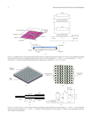
Figure 3: (a) Return loss and isolation versus frequency of one element of dual-polarized antenna element. (b) Gain versus frequency of one
element of dual polarized antenna element. (c) Isolation. (d) Return loss versus frequency of 8 × 8 array antenna.
Table 1: Wideband dual-polarized patch antenna specification.
Frequency range 5.15–5.9 GHz
Peak gain 26 dBi
Horizontal beamwidth 6◦
Vertical beamwidth 7◦
Front/back ratio Better than 28 dB
SLL
Vertical: −11 dB (center frequency)
Horizontal: −14 dB (center frequency)
Polarization (Dual) vertical or horizontal
VSWR 1.9 : 1 (max)
Impedance 50 Ohms
Mechanical Specification Length = width: 44 cm; depth: 4 cm
The antenna consists of only one substrate (Rogers TMM 4
with dielectric constant εr = 4.5), an air layer for enhancing
the bandwidth, and a radome. The input impedance of the
antenna at the center of the slot is given by [13, 14]
Zin =
n2
2
n2
1Ypatch + Yap
− jZ0mcot βmLs , (1)
where Ypatch is the patch admittance and Yap is the aperture
admittance (Figure 1(b)). Z0m, βm, and Ls are the microstrip
line parameters in this equation. Also the coupling of the
patch to the microstrip line is described by a transformer
[14]. The dimensions of the element antenna such as slots,
feed lines, circular patch, and spaces between them are
optimized with the use of IE3D to achieve best radiation
characteristics, wide impedance bandwidth, and high iso-
lation between two ports. The optimized element antenna
has a circular patch with 11.89 mm radius positioned at
the bottom side of Rohacell. Furthermore, two 50 ohms
microstrip feed lines (W = 1.5 mm, LV = 15 mm, and LH =
23 mm) at the bottom side of the substrate (Rogers TMM 4
4. 4 International Journal of Antennas and Propagation
5 5.2 5.4 5.6 5.8 6
5
10
15
20
25
Frequency (GHz)
Fronttobackratio(dB)
Vertical
Horizontal
(a)
5 5.2 5.4 5.6 5.8 6
Frequency (GHz)
28
29
30
31
32
33
Fronttobackratio(dB)
Vertical
Horizontal
(b)
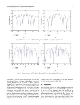
Figure 4: (a) Simulated front-to-back ratio versus frequency of 8 × 8 array antenna without plate at the back of antenna. (b) Measured
front-to-back ratio versus frequency of 8 × 8 array antenna with metal plate at the back of antenna.
Gain(dB)
5 5.2 5.4 5.6 5.8 6
Frequency (GHz)
Vertical
Horizontal
22
23
24
25
26
27
(a)
21
22
23
24
25
26
5 5.2 5.4 5.6 5.8 6
Frequency (GHz)
Gain(dB)
Vertical
Horizontal
(b)
Figure 5: Gain versus frequency of 8 × 8 array antenna: (a) simulated and (b) measured.
with hf = 0.762 mm, εr f = 4.5) are electromagnetically
coupled to circular patch through two rectangular slot
apertures in the common ground plane. As shown in
Figure 2, in order to reduce the antenna back lobes, a metallic
plate is located at the back of antenna, for example, 22 mm
from the bottom of the antenna structure. Additionally,
Figure 3(a) shows the simulated return loss for two ports
(S11 and S22) versus frequency for one element antenna and
Figure 3(b) shows simulated gain against frequency for one
element. As depicted in Figure 3, in the desired bandwidth
(5.1–5.9) return loss for both polarizations is more than
15 dB and the isolation between two ports (S12) is better than
35 dB.
3. Array Antenna
To obtain the desired radiation pattern characteristics, an
8 × 8 planar microstrip slot array antenna is designed
(Figure 2(a)). The bottom side of substrate consists of the
feeding network which is designed to give equal amplitude
and phase to each element (Figure 2(b)). Additionally,
by using T-junction design and a quarter-wave matching
transformer (Figure 2(c)), the feeds are matched to 50 ohms
feed line [15, 16]. To provide a match, the transformer
characteristic impedance Z1 should be Z1 = RinZ0, where
Z0 is the characteristic impedance of the input transmission
line and Rin is the input impedance of the antenna. The
5. International Journal of Antennas and Propagation 5
−60
−50
−40
−30
−20
−10
0
Normalizedgain(dB)
plane
plane
−50 0 50 90−90
θ
H
E
(a)
−60
−50
−40
−30
−20
−10
0
Normalizedgain(dB)
−50 0 50 90−90
θ
planeH
planeE
(b)
Figure 6: Simulated antenna far-field radiation pattern at 5.5 GHz: (a) vertical and (b) horizontal.
−80 20 40 60 80−60 −40 −20
−60
−50
−40
−30
−20
−10
0
Normalizedgain(dB)
plane
plane
0 90−90
θ
H
E
(a)
−60
−50
−40
−30
−20
−10
0
Normalizedgain(dB)
plane
plane
−50 0 50 90−90
θ
H
E
(b)
Figure 7: Measured antenna far-field radiation pattern at 5.5 GHz: (a) vertical and (b) horizontal.
transformer is usually another transmission line with the
desired characteristic impedance (Figure 2(d)). The spaces
between elements are set at 50 mm for better radiation
characteristics. The simulated and measured return loss (S11)
and isolation (S21) of 8 × 8 dual-polarized microstrip patch
slot array antenna are illustrated in Figures 3(c) and 3(d).
Furthermore, the metal plate at the back of array antenna
reduces the front-to-back ratio about −20 dB, as can be
seen in Figure 4. Likewise, the gain of the array antenna in
different frequencies is demonstrated in Figure 5. Moreover,
the simulated and measured E and H plane far-field radiation
patterns of the array antenna at center frequency are shown
in Figures 6 and 7. Finally, all vital parameters such as
antenna size, its gain, beamwidth, side lobe level, and front-
to-back ratio are summarized in Table 1.
4. Conclusions
This paper has reported the design of a low-cost high-gain
dual-polarized patch array antenna for WiMAX applications
in the 5.15–5.9 GHz frequency band. The antenna has an
approximately bandwidth of 14% and the peak gain of 26 dBi
for both polarizations. The design has been achieved with
the use of commercial software packages AWR Microwave
Office and Zeland IE3D. The design process aimed at best
return losses and fine quality radiation characteristics over
6. 6 International Journal of Antennas and Propagation
the assumed frequency band. The designed antenna has an
impedance bandwidth of approximately 14% and the peak
gain of approximately 26 dBi for both polarizations. This
performance has been confirmed experimentally.
References
[1] C. A. Balanis, Antenna Theory, Analysis and Design, John Wiley
& Sons, 3rd edition, 2005.
[2] K. L. Wong, Planar Antennas for Wireless Communications,
John Wiley & Sons, 2003.
[3] S. B. Chen, Y. C. Jiao, W. Wang, and F. S. Zhang, “Modified T-
shaped planar monopole antennas for multiband operation,”
IEEE Transactions on Microwave Theory and Techniques, vol.
54, no. 8, pp. 3267–3270, 2006.
[4] W. C. Liu and C. F. Hsu, “Dual-band CPW-fed Y-shaped
monopole antenna for PCS/WLAN application,” Electronics
Letters, vol. 41, no. 7, pp. 390–391, 2005.
[5] W. C. Liu, “Broadband dual-frequency meandered CPW-fed
monopole antenna,” Electronics Letters, vol. 40, no. 21, pp.
1319–1320, 2004.
[6] J. Y. Li, J. L. Guo, Y. B. Gan, and Q. Z. Liu, “The tri-
band performance of sleeve dipole antenna,” Journal of
Electromagnetic Waves and Applications, vol. 19, no. 15, pp.
2081–2092, 2005.
[7] K. M. Z. Shams, M. Ali, and H. S. Hwang, “A planar induc-
tively coupled bow-tie slot antenna for WLAN application,”
Journal of Electromagnetic Waves and Applications, vol. 20, no.
7, pp. 861–871, 2006.
[8] C. Y. Wu, S. H. Yeh, and T. H. Lu, “Novel high gain
metamaterial antenna radome for WiMAX operation in the
5.8-GHz band,” in IEEE Antennas and Propagation Society
International Symposium (AP-S ’07), pp. 3488–3491, June
2007.
[9] L. N. Zhangl, S. S. Zhongl, and X. L. Liang, “Dual-band dual-
polarized hybrid antenna array,” in PIERS Proceedings, Xi’an,
China, March 2010.
[10] S. D. Targonski, R. B. Waterhouse, and D. M. Pozar, “Design of
wide-band aperture-stacked patch microstrip antennas,” IEEE
Transactions on Antennas and Propagation, vol. 46, no. 9, pp.
1245–1251, 1998.
[11] D. M. Pozar and S. D. Targonski, “A shared-aperture dual-
band dual-polarized microstrip array,” IEEE Transactions on
Antennas and Propagation, vol. 49, no. 2, pp. 150–157, 2001.
[12] H. J. Song and M. E. Bialkowski, “Ku-band 16 × 16 planar
array with aperture-coupled microstrip-patch elements,” IEEE
Antennas and Propagation Magazine, vol. 40, no. 5, pp. 25–29,
1998.
[13] G. Vetharatnam, C. B. Kuan, and C. H. Teik, “Combined
feed network for a shared-aperture dual-band dual-polarized
array,” IEEE Antennas and Wireless Propagation Letters, vol. 4,
no. 1, pp. 297–299, 2005.
[14] R. Garg and P. Bhartia, Microstrip Antenna Design Handbook,
Artech House, 2001.
[15] B. N. Das and K. K. Joshi, “Impedance of a radiating slot in
the ground plane of a microstripline,” IEEE Transactions on
Antennas and Propagation, vol. 30, no. 5, pp. 922–926, 1982.
[16] J. R. James and P. S. Hall, Handbook of Microstrip Antennas,
IEE Electromagnetic Waves, Peter Peregrinus, 1989.
7. International Journal of
Aerospace
EngineeringHindawi Publishing Corporation
http://www.hindawi.com Volume 2010
Robotics
Journal of
Hindawi Publishing Corporation
http://www.hindawi.com Volume 2014
Hindawi Publishing Corporation
http://www.hindawi.com Volume 2014
Active and Passive
Electronic Components
Control Science
and Engineering
Journal of
Hindawi Publishing Corporation
http://www.hindawi.com Volume 2014
International Journal of
Rotating
Machinery
Hindawi Publishing Corporation
http://www.hindawi.com Volume 2014
Hindawi Publishing Corporation
http://www.hindawi.com
Journal of
Engineering
Volume 2014
Submit your manuscripts at
http://www.hindawi.com
VLSI Design
Hindawi Publishing Corporation
http://www.hindawi.com Volume 2014
Hindawi Publishing Corporation
http://www.hindawi.com Volume 2014
Shock and Vibration
Hindawi Publishing Corporation
http://www.hindawi.com Volume 2014
Civil Engineering
Advances in
Acoustics and Vibration
Advances in
Hindawi Publishing Corporation
http://www.hindawi.com Volume 2014
Hindawi Publishing Corporation
http://www.hindawi.com Volume 2014
Electrical and Computer
Engineering
Journal of
Advances in
OptoElectronics
Hindawi Publishing Corporation
http://www.hindawi.com
Volume 2014
The Scientific
World JournalHindawi Publishing Corporation
http://www.hindawi.com Volume 2014
Sensors
Journal of
Hindawi Publishing Corporation
http://www.hindawi.com Volume 2014
Modelling &
Simulation
in Engineering
Hindawi Publishing Corporation
http://www.hindawi.com Volume 2014
Hindawi Publishing Corporation
http://www.hindawi.com Volume 2014
Chemical Engineering
International Journal of Antennas and
Propagation
International Journal of
Hindawi Publishing Corporation
http://www.hindawi.com Volume 2014
Hindawi Publishing Corporation
http://www.hindawi.com Volume 2014
Navigation and
Observation
International Journal of
Hindawi Publishing Corporation
http://www.hindawi.com Volume 2014
Distributed
Sensor Networks
International Journal of