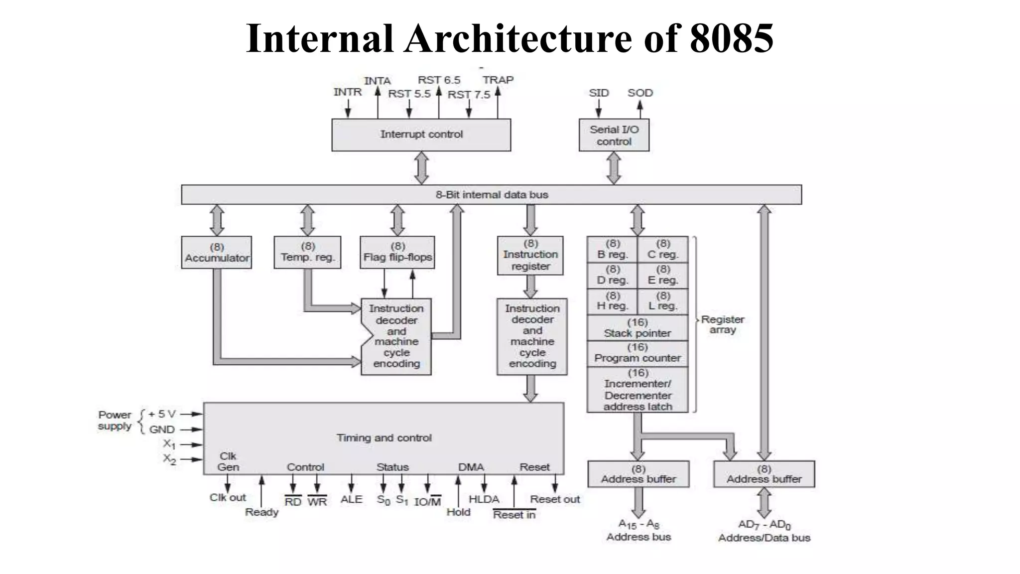
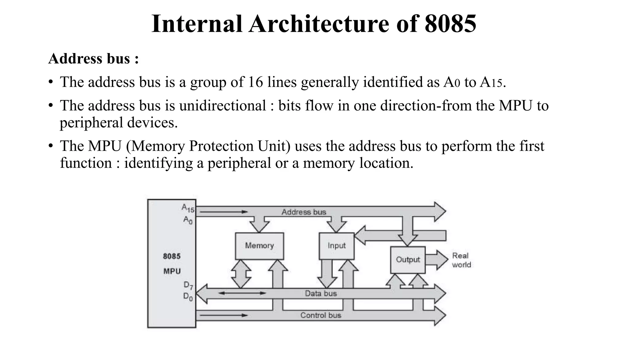
The 8085 microprocessor has an address bus with 16 lines to identify memory locations and peripheral devices. It has an 8-line bi-directional data bus to transfer data. The control bus carries synchronization and timing signals. The 8085 has six general-purpose registers, an accumulator, flags register, program counter, stack pointer, and temporary register. The arithmetic logic unit performs operations using data from the accumulator and registers.
Computer system architecture (microprocessor 8085) unit 4Anjaan Gajendra
Microprocessor: Organization of 8085 microprocessor, Instruction set of 8085, Mnemonics and operation codes
of data transfer group, Arithmetic group, Logic group, Branches group and stack, I/O and Machine control group,
Assembly language, Assembler, Simple programs in assembly language.
The microprocessor is the central processing unit of a computer. It is the heart of the computer. 8085 is one of the most popular 8-Bit microprocessors in India. Because of its unique characteristics of both industry and academics still regarded as standard this microprocessor.
1. 8-Bit Microprocessor:
The 8085 is an 8-bit microprocessor, which means it can process data in 8-bit chunks at a time. This restricts the processor to working with values from 0 to 255.
2. Architecture:
The 8085 microprocessor has a simple architecture consisting of various registers, a control unit, and an arithmetic logic unit (ALU).
It has 74 instructions and 246 opcodes.
3. Registers:
Accumulator (A): Used for performing arithmetic and logic operations.
General-Purpose Registers (B, C, D, E, H, L): Used for various data manipulation tasks.
Stack Pointer (SP): Used to manage the stack.
Program Counter (PC): Keeps track of the address of the next instruction to be executed.
4. Memory:
The 8085 microprocessor can address up to 64KB of memory, which includes RAM (Random Access Memory) and ROM (Read-Only Memory).
Memory is organized into 16-bit addresses.
5. Data and Address Bus:
The 8085 has an 8-bit data bus and a 16-bit address bus, allowing it to communicate with external memory and peripheral devices.7. Instruction Set:
The 8085 uses a Reduced Instruction Set Computer (RISC) architecture with a relatively small instruction set. Instructions are categorized into data transfer, arithmetic and logical operations, control flow, and input/output operations.
8. Addressing Modes:
The 8085 supports various addressing modes, such as direct addressing, immediate addressing, register indirect addressing, and more, allowing for flexible data manipulation.
9. Interrupts:
The 8085 microprocessor features five interrupt lines, which are used for handling external interrupts. It supports both maskable and non-maskable interrupts.
10. Flags:7. Instruction Set:
The 8085 uses a Reduced Instruction
Harnessing WebAssembly for Real-time Stateless Streaming PipelinesChristina Lin
Traditionally, dealing with real-time data pipelines has involved significant overhead, even for straightforward tasks like data transformation or masking. However, in this talk, we’ll venture into the dynamic realm of WebAssembly (WASM) and discover how it can revolutionize the creation of stateless streaming pipelines within a Kafka (Redpanda) broker. These pipelines are adept at managing low-latency, high-data-volume scenarios.
Hierarchical Digital Twin of a Naval Power SystemKerry Sado
A hierarchical digital twin of a Naval DC power system has been developed and experimentally verified. Similar to other state-of-the-art digital twins, this technology creates a digital replica of the physical system executed in real-time or faster, which can modify hardware controls. However, its advantage stems from distributing computational efforts by utilizing a hierarchical structure composed of lower-level digital twin blocks and a higher-level system digital twin. Each digital twin block is associated with a physical subsystem of the hardware and communicates with a singular system digital twin, which creates a system-level response. By extracting information from each level of the hierarchy, power system controls of the hardware were reconfigured autonomously. This hierarchical digital twin development offers several advantages over other digital twins, particularly in the field of naval power systems. The hierarchical structure allows for greater computational efficiency and scalability while the ability to autonomously reconfigure hardware controls offers increased flexibility and responsiveness. The hierarchical decomposition and models utilized were well aligned with the physical twin, as indicated by the maximum deviations between the developed digital twin hierarchy and the hardware.
NO1 Uk best vashikaran specialist in delhi vashikaran baba near me online vas...Amil Baba Dawood bangali
Contact with Dawood Bhai Just call on +92322-6382012 and we'll help you. We'll solve all your problems within 12 to 24 hours and with 101% guarantee and with astrology systematic. If you want to take any personal or professional advice then also you can call us on +92322-6382012 , ONLINE LOVE PROBLEM & Other all types of Daily Life Problem's.Then CALL or WHATSAPP us on +92322-6382012 and Get all these problems solutions here by Amil Baba DAWOOD BANGALI
#vashikaranspecialist #astrologer #palmistry #amliyaat #taweez #manpasandshadi #horoscope #spiritual #lovelife #lovespell #marriagespell#aamilbabainpakistan #amilbabainkarachi #powerfullblackmagicspell #kalajadumantarspecialist #realamilbaba #AmilbabainPakistan #astrologerincanada #astrologerindubai #lovespellsmaster #kalajaduspecialist #lovespellsthatwork #aamilbabainlahore#blackmagicformarriage #aamilbaba #kalajadu #kalailam #taweez #wazifaexpert #jadumantar #vashikaranspecialist #astrologer #palmistry #amliyaat #taweez #manpasandshadi #horoscope #spiritual #lovelife #lovespell #marriagespell#aamilbabainpakistan #amilbabainkarachi #powerfullblackmagicspell #kalajadumantarspecialist #realamilbaba #AmilbabainPakistan #astrologerincanada #astrologerindubai #lovespellsmaster #kalajaduspecialist #lovespellsthatwork #aamilbabainlahore #blackmagicforlove #blackmagicformarriage #aamilbaba #kalajadu #kalailam #taweez #wazifaexpert #jadumantar #vashikaranspecialist #astrologer #palmistry #amliyaat #taweez #manpasandshadi #horoscope #spiritual #lovelife #lovespell #marriagespell#aamilbabainpakistan #amilbabainkarachi #powerfullblackmagicspell #kalajadumantarspecialist #realamilbaba #AmilbabainPakistan #astrologerincanada #astrologerindubai #lovespellsmaster #kalajaduspecialist #lovespellsthatwork #aamilbabainlahore #Amilbabainuk #amilbabainspain #amilbabaindubai #Amilbabainnorway #amilbabainkrachi #amilbabainlahore #amilbabaingujranwalan #amilbabainislamabad
HEAP SORT ILLUSTRATED WITH HEAPIFY, BUILD HEAP FOR DYNAMIC ARRAYS.
Heap sort is a comparison-based sorting technique based on Binary Heap data structure. It is similar to the selection sort where we first find the minimum element and place the minimum element at the beginning. Repeat the same process for the remaining elements.
6th International Conference on Machine Learning & Applications (CMLA 2024)ClaraZara1
6th International Conference on Machine Learning & Applications (CMLA 2024) will provide an excellent international forum for sharing knowledge and results in theory, methodology and applications of on Machine Learning & Applications.
3. Internal Architecture of 8085
Address bus :
• The address bus is a group of 16 lines generally identified as A0 to A15.
• The address bus is unidirectional : bits flow in one direction-from the MPU to
peripheral devices.
• The MPU (Memory Protection Unit) uses the address bus to perform the first
function : identifying a peripheral or a memory location.
4. Internal Architecture of 8085
Data bus :
• The data bus is a group of eight lines used for data flow.
• These lines are bi-directional - data flow in both directions between the MPU and
• memory and peripheral devices.
• The MPU uses the data bus to perform the second function: transferring binary
information.
Control bus :
• The control bus carries synchronization signals and providing timing signals.
• The MPU generates specific control signals for every operation it performs.
• These signals are used to identify a device type with which the MPU wants to
communicate.
5. Internal Architecture of 8085
Registers of 8085 :
• The 8085 have six general - purpose registers to store 8-bit data during program
execution.
• These registers are identified as B, C, D, E, H, and L.
• They can be combined as register pairs - BC, DE, and HL - to perform some 16 - bit
operations.
Accumulator (A) :
• The accumulator is an 8 - bit register that is part of the arithmetic/logic unit (ALU).
• This register is used to store 8-bit data and to perform arithmetic and logical
operations.
• The result of an operation is stored in the accumulator.
6. Internal Architecture of 8085
Flags :
• The ALU includes five flip-flops that are set or reset according to the result of an
• operation.
• The microprocessor uses the flags for testing the data conditions.
• They are Zero (Z), Carry (CY), Sign (S), Parity (P) and Auxiliary Carry (AC) flags.
• The most commonly used flags are Sign, Zero and Carry.
• The bit position for the flags in flag register is Accumulator (A)
Sign flag (S) :
• After execution of any arithmetic and logical operation, if D7 of the result is 1, the sign flag is set.
• If D, is 1, the number will be viewed as negative number. If D7 is 0, the number will be viewed as
positive number.
Zero flag (z) :
• If the result of arithmetic and logical operation is zero, then zero flag is set, otherwise it is reset.
7. Internal Architecture of 8085
Arithmetic and Logic Unit (ALU) :
• It is used to perform the arithmetic operations like addition, subtraction, multiplication,
division, increment and decrement and logical operations like AND, OR and EX-OR.
• It receives the data from accumulator and registers.
• According to the result it set or reset the flags.
Program Counter (PC) :
• This 16-bit register sequencing the execution of instructions.
• It is a memory pointer. Memory locations have 16-bit addresses, and that is why
• this is a 16-bit register.
• The function of the program counter is to point to the memory address of the next
• instruction to be executed.
8. Internal Architecture of 8085
Stack Pointer (SP) :
• The stack pointer is also a 16-bit register used as a memory pointer.
• It points to a memory location in R/W memory, called the stack.
• The beginning of the stack is defined by loading a 16-bit address in the stack pointer (register).
Temporary Register :
It is used to hold the data during the arithmetic and logical operations.
Instruction Register :
When an instruction is fetched from the memory, it is loaded in the instruction register.
Instruction Decoder :
It gets the instruction from the instruction register and decodes the instruction. It identifies the
instruction to be performed.
Serial I/O Control :
It has two control signals named SID and SOD for serial data transmission.
9. Internal Architecture of 8085
Timing and Control Unit :
• It has three control signals ALE (Address Enable Latch), RD (Active low) and
WR (Active low) and three status signals IO/M(Active low).
• ALE is used for provide control signal to synchronize the components of
• microprocessor and timing for instruction to perform the operation.
• RD (Active low) and WR (Active low) are used to indicate whether the
operation is reading the data from memory or writing the data into memory
respectively.
• IO/M (Active low) is used to indicate whether the operation is belongs to the
memory or peripherals.
10. Internal Architecture of 8085
Interrupt Control Unit :
• It receives hardware interrupt signals and sends an acknowledgement for
receiving the interrupt signal.