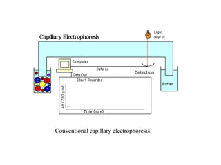
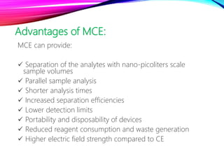
MICROCHIP CAPILLARY
ELECTROPHORESIS–MASS
SPECTROMETRY
By
Shereen Mohamed Shehata
Supervised by
Dr. Sarah Al-Rashood
Pharmaceutical Chemistry Department
College of Pharmacy, King Saud University
1- Introduction
• Microchip capillary electrophoresis (MCE) is a modification of
conventional capillary electrophoresis (CE) on a smaller scale
• MCE components are similar to those of conventional CE
Conventional capillary electrophoresis
Detection
Advantages of MCE:
MCE can provide:
 Separation of the analytes with nano-picoliters scale
sample volumes
 Parallel sample analysis
 Shorter analysis times
 Increased separation efficiencies
 Lower detection limits
 Portability and disposability of devices
 Reduced reagent consumption and waste generation
 Higher electric field strength compared to CE
Coupling mass spectrometric (MS) detection with MCE allows:
 Highly selective detection
 Structural information of the analytes
2- Microchip design
 In MCE–MS, it is important to combine a separation
channel with an ionization interface on a single microchip
Classical microchip for the electrophoretic analyses consists
of:
• Four reservoirs
• A cross-type injector
• A separation channel
2.1. Chip material
Substrate materials for MCE should:
(i) Support a stable electroosmotic flow (EOF)
(ii) Have good optical clarity
(iii) Be easily microfabricated
(iv) Be compatible with the running buffer
(v) Have good thermal/electrical properties to minimize
Joule heating or electrical breakdown
a) Quartz and glass
Advantages:
 Inert towards a variety of different solvents
 Give a faster EOF so, the separation time can be reduced
 A wide variety of the coating techniques is advantageous
for suppressing the adsorption of analytes onto the
microchannel
a) Quartz and glass
Disadvantages:
 The production is expensive and time-consuming
 The devices are fragile
So, cheap polymeric materials have been used as the chip
substrates.
b) Poly (dimethylsiloxane) (PDMS)
• Is the most popular polymer in microfabrication technology
• However, PDMS generates a reduced EOF relative to that of
glass, which can influence the efficiency of separation
c) Poly (methylmethacrylate) (PMMA)
Advantages:
• Has high thermal conductivity
• Low cost
• High dielectric constant
• Easily fabricated
d) SU-8
• Recently utilized as a chip material
• It is a chemically stable material with glass-like surface
properties with respect of the surface charge and EOF
• These polymeric materials are disposable
2.2. Channel geometry
• Multiple channels can be combined without any connector
• Typically, MCE consists of injection channel that may be:
 Cross- injection channel layout
 T- injection channel layout
 Double-T injection channel layout
• Another channel, crossed to the injection channel, for the
separation
Typical channel designs for MCE: (a) cross injection, (b) T-injection, and
(c) double-T injection channel layouts
• To increase resolution in MCE we can use folded separation
channels (spiral-shaped) so, increasing the length of the
separation channel while maintaining small chip size
• Also, on-line sample preconcentration was found to
enhance both the plate numbers and sensitivities
3. Ionization interface
Ranging from
small molecules
to large peptides
and proteins
For ionizing
analytes
dissolved in a
liquid phase
Electrospray
ionization (ESI) is
the most suitable
Electrospray is produced directly from the
microchannel outlet
On-chip
ionization
External emitter, such as fused silica capillary, a
nanospray needle, or a microsprayer attached to
the microchannel outlet
Off-chip
ionization
Chip-based ESI interfacing techniques can be divided into:
Considerations for coupling microchip to
MS
• Minimization of dead volume
• Establishing a steady flow rate for sample introduction
• Minimizing sample adsorption to the microfluidic device
• Solvent compatibility of the device
• Careful selection of the pH, as this will determine:
The analyte charge
The magnitude and direction of EOF
3.1. ESI interface using tapered capillary tip
• The nanospray tip was attached to an opening drilled at the
end of a separation channel of a glass microchip
• When a five peptide mixture is analyzed by this MCE–MS,
three peptides are detected as a single peak due to serious
peak broadening
Modifications to improve the tapered capillary tip
efficiency and eliminate band broadening
a) Dead volume elimination:
 By removing the conical shape of the access hole
 Using a glass microchip having a monolithically integrated
tapered ESI emitter
The dead-volume-free MCE–MS device is very attractive
especially for the analysis of proteins and metabolites
b) Laminar flow induced by the negative pressure at the
tip can be controlled by:
 Developing a microchip to which the spray tip can be
attached using a PEEK screw without adhesive
 Using a microchip with a long separation channel
 The length of the inserted capillary tip should be kept to a
minimum
The microchip modified along these findings can realize the
MCE–MS analysis of drug components, peptides, tryptic
digestions, and proteins
c) Clogging in the fine ESI tip and/or narrow separation
channel can be solved by:
 The use of disposable chip substrates such as PDMS,
and cyclic olefin polymer (COP)
 By coating the channel surface with hydroxypropylmethyl
cellulose (HPMC), the efficiency can be improved from
numbers of 20,000 to 89,000
3.2. Sheath-liquid and gas assisted
microsprayer ESI interface
• Using teflon/stainless-steel tubes and liquid junction based
microsprayer
• The liquid junction acts as a hydrodynamic and flowing
liquid bridge between the exit of the separation channel
and the inlet of the microsprayer
Schematic drawing of the MCE/MS apparatus and the expanded view of the liquid
junction
Applications of microsprayer
 Carnitine and three acetylcarnitines in human urine are
separated in less than 48 seconds
 Analysis of human plasma samples containing imipramine
and desipramine
 Glycoproteins and glycopeptides are successfully analyzed
with a limit of detection (LOD) at femtomole level
3.3. Chamber-type ESI interface
• A sub-atmospheric chamber-type results in a stable flow
volume and ESI
• By using the developed ESI interface:
 Eight-angiotensin peptide mixture
 Four-protein mixture
 Bovine serum albumin (BSA) tryptic digests
Successfully
separated
and detected
within 8 min
3.4. ESI interface using metal coated
capillary
• An ESI interface with a metalized nanospray, which allows
the direct application of the ESI voltage
 To improve the detection sensitivity, on-line sample
preconcentration has been carried out
 A conductive rubber coated nanospray was used to obtain
longer lifetime and robustness
3.4. ESI interface using metal coated
capillary (cont.)
 To suppress band broadening, a hybrid nanospray ESI
interface in which PDMS nanospray structure is coated with
graphite powder to provide electric conductivity
3.5. ESI interface monolithically integrating
sharp-pointed structure
• Recently, spray emitters with more simple structures and a
dynamic coating of the PDMS channel with a cationic
polymer, PolyE-323, has been developed
 Three peptide sample can be separated with acceptable
resolution
 However, the separation efficiencies and detection
sensitivities are insufficient
 This may be due to the formation of a large Taylor cone at
the ESI emitter tip
3.6. LDI interface
• The high sensitivity of matrix assisted laser
desorption/ionization (MALDI) for large biomolecules
makes it ideal for interfacing with microdevices
• A combination of a gel electrophoresis chip with matrix free
infrared- LDI (IR-LDI) has been used for detection of
bradykinin and bovine insulin
3.6. LDI interface (cont.)
 Microchip isoelectric focusing MCIEF–MALDI technique
using a resin tape cover and freeze-drying process has
been developed
 The band widths of separated proteins remain constant
before and after the fixation by freeze-drying
Thus, no band broadening during the transfer process from
MCIEF to MALDI resulting in good resolution of proteins
Schematic representation of experimental procedure in MCIEF–MALDI-MS.
Illustrations show cross-sectional views of chip during each process
4. Coupling of MCE–MS with packed beds
• By combining a sample pretreatment site with an
electrophoretic separation channel
 To combine protein digestion with MCE–MS, a microchip
consisting of immobilized trypsin bead beds has been
fabricated
 A microchip format packed with C18 RP-packings has been
employed to the preconcentration of tryptic digests,
resulting in the LOD of 5 nM
5. Applications
The advances in MCE–MS have been applied to the analysis
of:
 Amino acids
 Peptides
 Tryptic digests
 Proteins
 Amines
 Sugars
 Pharmaceutical compounds
5. Applications (cont.)
• Through the advances in the development of novel
ionization interface and channel coating techniques, the
applications of MCE–MS will be extended to various areas
such as :
 Clinical
 Food
 Forensic
 Environmental researches
6. Conclusion and future perspectives
MCE–MS has a great potential in bioanalysis
It can provide speed analyses in seconds and high efficiencies
For MS detection, two types of ionization interfaces, ESI and LDI
Multiple separation channels can be combined on microchips without any connector
6. Conclusion and future perspectives (cont.)
 On the other hand, introduction of a universal ionization
method, both in macro- and microscales, remains another
great challenge for the future development
 As well, quite different types of solutions may be awaiting
widespread use. Just one example is a recently reported
carbon-nanotube nanomechanical resonator, which is
capable of measuring masses of individual atoms without
ionization
Microfluidics

Microfluidics

  • 1.
    MICROCHIP CAPILLARY ELECTROPHORESIS–MASS SPECTROMETRY By Shereen MohamedShehata Supervised by Dr. Sarah Al-Rashood Pharmaceutical Chemistry Department College of Pharmacy, King Saud University
  • 2.
    1- Introduction • Microchipcapillary electrophoresis (MCE) is a modification of conventional capillary electrophoresis (CE) on a smaller scale • MCE components are similar to those of conventional CE
  • 3.
  • 4.
    Advantages of MCE: MCEcan provide:  Separation of the analytes with nano-picoliters scale sample volumes  Parallel sample analysis  Shorter analysis times  Increased separation efficiencies  Lower detection limits  Portability and disposability of devices  Reduced reagent consumption and waste generation  Higher electric field strength compared to CE
  • 5.
    Coupling mass spectrometric(MS) detection with MCE allows:  Highly selective detection  Structural information of the analytes
  • 6.
    2- Microchip design In MCE–MS, it is important to combine a separation channel with an ionization interface on a single microchip Classical microchip for the electrophoretic analyses consists of: • Four reservoirs • A cross-type injector • A separation channel
  • 7.
    2.1. Chip material Substratematerials for MCE should: (i) Support a stable electroosmotic flow (EOF) (ii) Have good optical clarity (iii) Be easily microfabricated (iv) Be compatible with the running buffer (v) Have good thermal/electrical properties to minimize Joule heating or electrical breakdown
  • 8.
    a) Quartz andglass Advantages:  Inert towards a variety of different solvents  Give a faster EOF so, the separation time can be reduced  A wide variety of the coating techniques is advantageous for suppressing the adsorption of analytes onto the microchannel
  • 9.
    a) Quartz andglass Disadvantages:  The production is expensive and time-consuming  The devices are fragile So, cheap polymeric materials have been used as the chip substrates.
  • 10.
    b) Poly (dimethylsiloxane)(PDMS) • Is the most popular polymer in microfabrication technology • However, PDMS generates a reduced EOF relative to that of glass, which can influence the efficiency of separation
  • 11.
    c) Poly (methylmethacrylate)(PMMA) Advantages: • Has high thermal conductivity • Low cost • High dielectric constant • Easily fabricated
  • 12.
    d) SU-8 • Recentlyutilized as a chip material • It is a chemically stable material with glass-like surface properties with respect of the surface charge and EOF • These polymeric materials are disposable
  • 13.
    2.2. Channel geometry •Multiple channels can be combined without any connector • Typically, MCE consists of injection channel that may be:  Cross- injection channel layout  T- injection channel layout  Double-T injection channel layout • Another channel, crossed to the injection channel, for the separation
  • 14.
    Typical channel designsfor MCE: (a) cross injection, (b) T-injection, and (c) double-T injection channel layouts
  • 15.
    • To increaseresolution in MCE we can use folded separation channels (spiral-shaped) so, increasing the length of the separation channel while maintaining small chip size • Also, on-line sample preconcentration was found to enhance both the plate numbers and sensitivities
  • 16.
    3. Ionization interface Rangingfrom small molecules to large peptides and proteins For ionizing analytes dissolved in a liquid phase Electrospray ionization (ESI) is the most suitable
  • 17.
    Electrospray is produceddirectly from the microchannel outlet On-chip ionization External emitter, such as fused silica capillary, a nanospray needle, or a microsprayer attached to the microchannel outlet Off-chip ionization Chip-based ESI interfacing techniques can be divided into:
  • 18.
    Considerations for couplingmicrochip to MS • Minimization of dead volume • Establishing a steady flow rate for sample introduction • Minimizing sample adsorption to the microfluidic device • Solvent compatibility of the device • Careful selection of the pH, as this will determine: The analyte charge The magnitude and direction of EOF
  • 19.
    3.1. ESI interfaceusing tapered capillary tip • The nanospray tip was attached to an opening drilled at the end of a separation channel of a glass microchip • When a five peptide mixture is analyzed by this MCE–MS, three peptides are detected as a single peak due to serious peak broadening
  • 20.
    Modifications to improvethe tapered capillary tip efficiency and eliminate band broadening a) Dead volume elimination:  By removing the conical shape of the access hole  Using a glass microchip having a monolithically integrated tapered ESI emitter The dead-volume-free MCE–MS device is very attractive especially for the analysis of proteins and metabolites
  • 21.
    b) Laminar flowinduced by the negative pressure at the tip can be controlled by:  Developing a microchip to which the spray tip can be attached using a PEEK screw without adhesive  Using a microchip with a long separation channel  The length of the inserted capillary tip should be kept to a minimum The microchip modified along these findings can realize the MCE–MS analysis of drug components, peptides, tryptic digestions, and proteins
  • 22.
    c) Clogging inthe fine ESI tip and/or narrow separation channel can be solved by:  The use of disposable chip substrates such as PDMS, and cyclic olefin polymer (COP)  By coating the channel surface with hydroxypropylmethyl cellulose (HPMC), the efficiency can be improved from numbers of 20,000 to 89,000
  • 23.
    3.2. Sheath-liquid andgas assisted microsprayer ESI interface • Using teflon/stainless-steel tubes and liquid junction based microsprayer • The liquid junction acts as a hydrodynamic and flowing liquid bridge between the exit of the separation channel and the inlet of the microsprayer
  • 24.
    Schematic drawing ofthe MCE/MS apparatus and the expanded view of the liquid junction
  • 25.
    Applications of microsprayer Carnitine and three acetylcarnitines in human urine are separated in less than 48 seconds  Analysis of human plasma samples containing imipramine and desipramine  Glycoproteins and glycopeptides are successfully analyzed with a limit of detection (LOD) at femtomole level
  • 26.
    3.3. Chamber-type ESIinterface • A sub-atmospheric chamber-type results in a stable flow volume and ESI • By using the developed ESI interface:  Eight-angiotensin peptide mixture  Four-protein mixture  Bovine serum albumin (BSA) tryptic digests Successfully separated and detected within 8 min
  • 27.
    3.4. ESI interfaceusing metal coated capillary • An ESI interface with a metalized nanospray, which allows the direct application of the ESI voltage  To improve the detection sensitivity, on-line sample preconcentration has been carried out  A conductive rubber coated nanospray was used to obtain longer lifetime and robustness
  • 28.
    3.4. ESI interfaceusing metal coated capillary (cont.)  To suppress band broadening, a hybrid nanospray ESI interface in which PDMS nanospray structure is coated with graphite powder to provide electric conductivity
  • 29.
    3.5. ESI interfacemonolithically integrating sharp-pointed structure • Recently, spray emitters with more simple structures and a dynamic coating of the PDMS channel with a cationic polymer, PolyE-323, has been developed  Three peptide sample can be separated with acceptable resolution  However, the separation efficiencies and detection sensitivities are insufficient  This may be due to the formation of a large Taylor cone at the ESI emitter tip
  • 30.
    3.6. LDI interface •The high sensitivity of matrix assisted laser desorption/ionization (MALDI) for large biomolecules makes it ideal for interfacing with microdevices • A combination of a gel electrophoresis chip with matrix free infrared- LDI (IR-LDI) has been used for detection of bradykinin and bovine insulin
  • 31.
    3.6. LDI interface(cont.)  Microchip isoelectric focusing MCIEF–MALDI technique using a resin tape cover and freeze-drying process has been developed  The band widths of separated proteins remain constant before and after the fixation by freeze-drying Thus, no band broadening during the transfer process from MCIEF to MALDI resulting in good resolution of proteins
  • 32.
    Schematic representation ofexperimental procedure in MCIEF–MALDI-MS. Illustrations show cross-sectional views of chip during each process
  • 33.
    4. Coupling ofMCE–MS with packed beds • By combining a sample pretreatment site with an electrophoretic separation channel  To combine protein digestion with MCE–MS, a microchip consisting of immobilized trypsin bead beds has been fabricated  A microchip format packed with C18 RP-packings has been employed to the preconcentration of tryptic digests, resulting in the LOD of 5 nM
  • 34.
    5. Applications The advancesin MCE–MS have been applied to the analysis of:  Amino acids  Peptides  Tryptic digests  Proteins  Amines  Sugars  Pharmaceutical compounds
  • 35.
    5. Applications (cont.) •Through the advances in the development of novel ionization interface and channel coating techniques, the applications of MCE–MS will be extended to various areas such as :  Clinical  Food  Forensic  Environmental researches
  • 36.
    6. Conclusion andfuture perspectives MCE–MS has a great potential in bioanalysis It can provide speed analyses in seconds and high efficiencies For MS detection, two types of ionization interfaces, ESI and LDI Multiple separation channels can be combined on microchips without any connector
  • 37.
    6. Conclusion andfuture perspectives (cont.)  On the other hand, introduction of a universal ionization method, both in macro- and microscales, remains another great challenge for the future development  As well, quite different types of solutions may be awaiting widespread use. Just one example is a recently reported carbon-nanotube nanomechanical resonator, which is capable of measuring masses of individual atoms without ionization