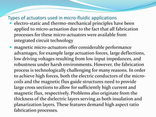
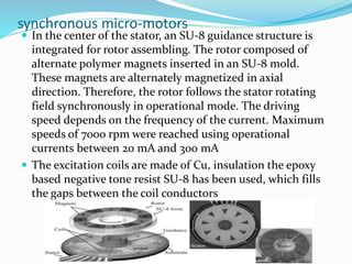
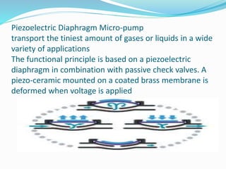
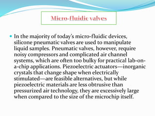
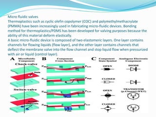
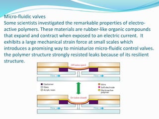
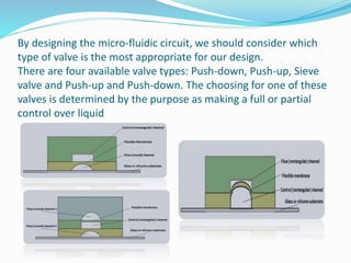
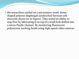
•AHMED M. ABDELGAWAD
•Ahmed.sayes@yahoo.com
Types of actuators used in micro-fluidic applications
 electro-static and thermo-mechanical principles have been
applied to micro-actuation due to the fact that all fabrication
processes for these micro-actuators were available from
integrated circuit technology
 magnetic micro-actuators offer considerable performance
advantages, for example large actuation forces, large deflections,
low driving voltages resulting from low input impedances, and
robustness under harsh environments. However, the fabrication
process is technologically challenging for many reasons. In order
to achieve high forces, both the electric conductors of the micro-
coils and the magnetic flux guide structures need to provide
large cross sections to allow for sufficiently high current and
magnetic flux, respectively. Problems also originate from the
thickness of the dielectric layers serving as both insulation and
planarization layers. These features demand high aspect ratio
fabrication processes.
synchronous micro-motors
 In the center of the stator, an SU-8 guidance structure is
integrated for rotor assembling. The rotor composed of
alternate polymer magnets inserted in an SU-8 mold.
These magnets are alternately magnetized in axial
direction. Therefore, the rotor follows the stator rotating
field synchronously in operational mode. The driving
speed depends on the frequency of the current. Maximum
speeds of 7000 rpm were reached using operational
currents between 20 mA and 300 mA
 The excitation coils are made of Cu, insulation the epoxy
based negative tone resist SU-8 has been used, which fills
the gaps between the coil conductors
 two synchronous motors are combined and enclosed by an SU-8
chamber wall.
 One gear driven by the three-phase system actuates the other gear
which rotates in the opposite direction. While rotating, the fluid is
drawn from the inlet, split to both gears and transported in the space
between the teeth and the chamber wall.
 The system is closed by a structured glass cover which is fixed on the
top of the chamber
 The pump rate is approximated by: Vp=Q* Vn *N
 where q is the number of spaces between two teeth, Vn is the volume of
one space and depends on the height, diameter, module and number of
teeth and N is the rotational speed.
Piezoelectric Diaphragm Micro-pump
transport the tiniest amount of gases or liquids in a wide
variety of applications
The functional principle is based on a piezoelectric
diaphragm in combination with passive check valves. A
piezo-ceramic mounted on a coated brass membrane is
deformed when voltage is applied
 In the majority of today’s micro-fluidic devices,
silicone pneumatic valves are used to manipulate
liquid samples. Pneumatic valves, however, require
noisy compressors and complicated air channel
systems, which are often too bulky for practical lab-on-
a-chip applications. Piezoelectric actuators—inorganic
crystals that change shape when electrically
stimulated—are feasible alternatives, but while
piezoelectric materials are less obtrusive than
pressurized air technology, they are excessively large
when compared to the size of the microchip itself.
Micro fluidic valves
Thermoplastics such as cyclic olefin copolymer (COC) and polymethylmethacrylate
(PMMA) have been increasingly used in fabricating micro-fluidic devices. Bonding
method for thermoplastics/PDMS has been developed for valving purposes because the
ability of this material deform elastically.
A basic micro-fluidic device is composed of two elastomeric layers. One layer contains
channels for flowing liquids (flow layer), and the other layer contains channels that
deflect the membrane valve into the flow channel and stop liquid flow when pressurized
with air or liquid (control layer).
Micro-fluidic valves
Some scientists investigated the remarkable properties of electro-
active polymers. These materials are rubber-like organic compounds
that expand and contract when exposed to an electric current. It
exhibits a large mechanical strain force at small scales which
introduces a promising way to miniaturize micro-fluidic control valves.
the polymer structure strongly resisted leaks because of its resilient
structure.
By designing the micro-fluidic circuit, we should consider which
type of valve is the most appropriate for our design.
There are four available valve types: Push-down, Push-up, Sieve
valve and Push-up and Push-down. The choosing for one of these
valves is determined by the purpose as making a full or partial
control over liquid
 the researchers settled on a micrometer-sized, dome-
shaped polymer diaphragm sandwiched between soft
electrode sheets (as in Figure). They tested its ability to
stop flow by fabricating it on top of a small hole drilled into
a micro-fluidic channel. By monitoring fluorescent
polystyrene tracking beads using high-speed video cameras
 References
 http://www.mdpi.com/2072-666X/5/3/442/htm
 http://web.stanford.edu/group/foundry/Available%20Valve%20Types.
html
 http://www.nanowerk.com/news2/newsid=31292.php

Micro pumps & micro valves

  • 1.
  • 2.
    Types of actuatorsused in micro-fluidic applications  electro-static and thermo-mechanical principles have been applied to micro-actuation due to the fact that all fabrication processes for these micro-actuators were available from integrated circuit technology  magnetic micro-actuators offer considerable performance advantages, for example large actuation forces, large deflections, low driving voltages resulting from low input impedances, and robustness under harsh environments. However, the fabrication process is technologically challenging for many reasons. In order to achieve high forces, both the electric conductors of the micro- coils and the magnetic flux guide structures need to provide large cross sections to allow for sufficiently high current and magnetic flux, respectively. Problems also originate from the thickness of the dielectric layers serving as both insulation and planarization layers. These features demand high aspect ratio fabrication processes.
  • 3.
    synchronous micro-motors  Inthe center of the stator, an SU-8 guidance structure is integrated for rotor assembling. The rotor composed of alternate polymer magnets inserted in an SU-8 mold. These magnets are alternately magnetized in axial direction. Therefore, the rotor follows the stator rotating field synchronously in operational mode. The driving speed depends on the frequency of the current. Maximum speeds of 7000 rpm were reached using operational currents between 20 mA and 300 mA  The excitation coils are made of Cu, insulation the epoxy based negative tone resist SU-8 has been used, which fills the gaps between the coil conductors
  • 4.
     two synchronousmotors are combined and enclosed by an SU-8 chamber wall.  One gear driven by the three-phase system actuates the other gear which rotates in the opposite direction. While rotating, the fluid is drawn from the inlet, split to both gears and transported in the space between the teeth and the chamber wall.  The system is closed by a structured glass cover which is fixed on the top of the chamber  The pump rate is approximated by: Vp=Q* Vn *N  where q is the number of spaces between two teeth, Vn is the volume of one space and depends on the height, diameter, module and number of teeth and N is the rotational speed.
  • 5.
    Piezoelectric Diaphragm Micro-pump transportthe tiniest amount of gases or liquids in a wide variety of applications The functional principle is based on a piezoelectric diaphragm in combination with passive check valves. A piezo-ceramic mounted on a coated brass membrane is deformed when voltage is applied
  • 6.
     In themajority of today’s micro-fluidic devices, silicone pneumatic valves are used to manipulate liquid samples. Pneumatic valves, however, require noisy compressors and complicated air channel systems, which are often too bulky for practical lab-on- a-chip applications. Piezoelectric actuators—inorganic crystals that change shape when electrically stimulated—are feasible alternatives, but while piezoelectric materials are less obtrusive than pressurized air technology, they are excessively large when compared to the size of the microchip itself.
  • 7.
    Micro fluidic valves Thermoplasticssuch as cyclic olefin copolymer (COC) and polymethylmethacrylate (PMMA) have been increasingly used in fabricating micro-fluidic devices. Bonding method for thermoplastics/PDMS has been developed for valving purposes because the ability of this material deform elastically. A basic micro-fluidic device is composed of two elastomeric layers. One layer contains channels for flowing liquids (flow layer), and the other layer contains channels that deflect the membrane valve into the flow channel and stop liquid flow when pressurized with air or liquid (control layer).
  • 8.
    Micro-fluidic valves Some scientistsinvestigated the remarkable properties of electro- active polymers. These materials are rubber-like organic compounds that expand and contract when exposed to an electric current. It exhibits a large mechanical strain force at small scales which introduces a promising way to miniaturize micro-fluidic control valves. the polymer structure strongly resisted leaks because of its resilient structure.
  • 9.
    By designing themicro-fluidic circuit, we should consider which type of valve is the most appropriate for our design. There are four available valve types: Push-down, Push-up, Sieve valve and Push-up and Push-down. The choosing for one of these valves is determined by the purpose as making a full or partial control over liquid
  • 10.
     the researcherssettled on a micrometer-sized, dome- shaped polymer diaphragm sandwiched between soft electrode sheets (as in Figure). They tested its ability to stop flow by fabricating it on top of a small hole drilled into a micro-fluidic channel. By monitoring fluorescent polystyrene tracking beads using high-speed video cameras
  • 11.
     References  http://www.mdpi.com/2072-666X/5/3/442/htm http://web.stanford.edu/group/foundry/Available%20Valve%20Types. html  http://www.nanowerk.com/news2/newsid=31292.php