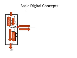
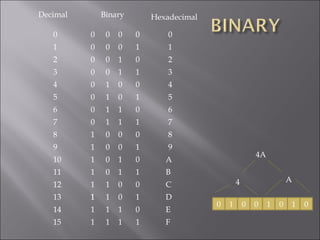
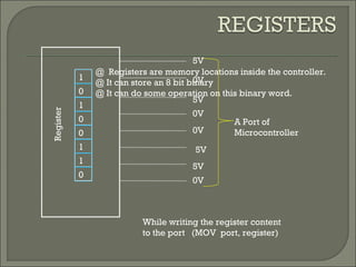
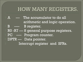
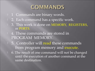
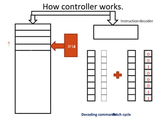
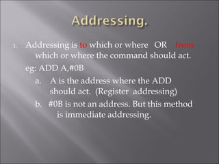
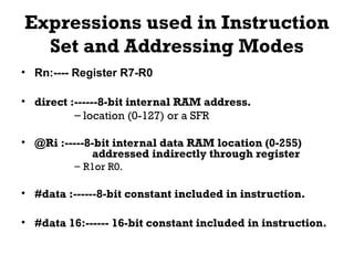
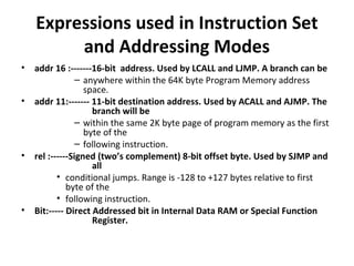
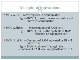
Basic Digital Concepts
Port OR Out Put of a
Digital Circuit
5 Volt Pin of IC
1 at this O/P =5V with 30mA source
0 at this O/P = 0V with 30 mA sink
GND pin of IC
+ve of 5V
-ve of 5V
150ohm
150ohm
Decimal Binary Hexadecimal
10
11
12
13
14
15
3
4
5
6
7
8
9
2
1
0
1 1 1
0 0 0 0
0 0 1 0
0 0 0 1
0 0 1 1
0 1 0 0
0 1 0 1
0 1 1 1
0 1 1 0
1 0 0 0
1 0 0 1
1 0 1 0
1 1 0 0
1 0 1 1
1 1 0 1
1 1 1 0
1
3
4
5
6
7
8
9
2
1
0
A
B
C
D
E
F
1
0 1 0 0 1 0 1 0
4A
4 A
1
0
0
1
0
0
1
@ Registers are memory locations inside the controller.
@ It can store an 8 bit binary
@ It can do some operation on this binary word.
A Port of
Microcontroller
Register
While writing the register content
to the port (MOV port, register)
5V
0V
0V
5V
0V
5V
5V
0V
1
0
1
1
1
0
1
0
0
 A --- The accumulator to do all
arithmetic and logic operation.
 B ---- B register.
 R0 -R7 --- 8 general purpose registers.
 PC ---- Program counter.
 DPTR --- Data pointer.
 Interrupt register and SFRs.
INTERNAL RAM
User Ram
Register bank
Bit addressable Ram
r5 r4 r3 r2r6 r1 r0r7 00
7F
B0B7
R2
If r2=3C
1 0 10 0 00 1
07
80 TO FF are SFRs
INTERNAL RAM
User Ram
Register bank
Bit addressable Ram
r5 r4 r3 r2r6 r1 r0r7 00
7F
B0B7
R2
If r2=3C
1 0 10 0 00 1
07
PROGRAM
MEMORY.
0000
0001
0002
3F12
3F13
3F14
FFFF
EXTERNAL
Total 64 K Bytes
INTERNAL
Total 4K Bytes.
000
FFF
 1 Commands are binary words.
 2. Each command has a specific work.
 3. This work is done on MEMORY, REGISTERS,
or PORTS.
 4. These commands are stored in
PROGRAM MEMORY.
 5. Controller will read these commands
from program memory and execute.
 6. The result of one command will not be changed
until the execution of another command at the
same destination.
How controller works.
MOV A,r0
ADD A,#0B
Programmemory
1
0
1
0
1
1
1
0
r0 A
Reading command OR Fetch cycle
DATA BUS
3F14
3F13
3F12
Decoding commands
EXECUTING
Program
counter
3F123F13
0
0
1
1
1
1
1
0
MOV A,r0
ADD A,#0B
3F14
Addressbus
AddressofP.G
1
0
1
1
0
0
0
0
0
1
0
0
0
1
1
0
JUMP
INSTRUCTION
LJMP and SJMP are used to Change
the flow of commands.
L JMP 3A20
ADD B,#F3ADD B,#F3
MOV P2,A
MOV A,r1
1F00
1F01
1F02
3A20
3A21
3A22
1F001F01
3A20
1F02
Program counter
Program memory
CALL
Instruction
LCALL A018
MOV A,P2
vv
LCALL A108
RRA
RRA
RRA
RRA
MOV A,@R1
Program Counter
A10
8A109
A10A
2101
2102
2100
02CA
02CB
A10B
A10C
02CC
02CA
2100
02CB
2101
A108
07
Stack
Pointer.
07
08
0B
0A
09
STACKRETA10D
0708
1. Addressing is to which or where OR from
which or where the command should act.
eg: ADD A,#0B
a. A is the address where the ADD
should act. (Register addressing)
b. #0B is not an address. But this method
is immediate addressing.
Expressions used in Instruction
Set and Addressing Modes
• Rn:---- Register R7-R0
• direct :------8-bit internal RAM address.
– location (0-127) or a SFR
• @Ri :-----8-bit internal data RAM location (0-255)
addressed indirectly through register
– R1or R0.
• #data :------8-bit constant included in instruction.
• #data 16:------ 16-bit constant included in instruction.
Expressions used in Instruction Set
and Addressing Modes
• addr 16 :-------16-bit address. Used by LCALL and LJMP. A branch can be
– anywhere within the 64K byte Program Memory address
space.
• addr 11:------- 11-bit destination address. Used by ACALL and AJMP. The
branch will be
– within the same 2K byte page of program memory as the first
byte of the
– following instruction.
• rel :------Signed (two’s complement) 8-bit offset byte. Used by SJMP and
all
• conditional jumps. Range is -128 to +127 bytes relative to first
byte of the
• following instruction.
• Bit:----- Direct Addressed bit in Internal Data RAM or Special Function
Register.
Examples of instructions.
MOV A,Rn Move register to Accumulator.
Eg:---MOV A, r2---- the contents of r2 will
move to Accumulator.
MOV A,direct ---- Move contents of RAM to A.
Eg:- MOV A, 6A ---the contents of RAM
location 6A will move to A
MOV A, @Ri ---Contents of RAM indicated by Ri will
move to A.
Eg:-- MOV A, @r1--- If r1=3B, the
contents of RAM location 3B will move to A.
Examples of instructions.
MOV A, #direct---- move the data immediate to A.
eg:-- MOV A, #2B-- the content of A will
be 2B.
INC --- increment.
DEC---- Decrement.
MUL---- Multiply.
ANL -----Logical AND.
ORL --- Logical OR
Doubts????????
Micro controller(pratheesh)

Micro controller(pratheesh)

  • 2.
    Basic Digital Concepts PortOR Out Put of a Digital Circuit 5 Volt Pin of IC 1 at this O/P =5V with 30mA source 0 at this O/P = 0V with 30 mA sink GND pin of IC +ve of 5V -ve of 5V 150ohm 150ohm
  • 3.
    Decimal Binary Hexadecimal 10 11 12 13 14 15 3 4 5 6 7 8 9 2 1 0 11 1 0 0 0 0 0 0 1 0 0 0 0 1 0 0 1 1 0 1 0 0 0 1 0 1 0 1 1 1 0 1 1 0 1 0 0 0 1 0 0 1 1 0 1 0 1 1 0 0 1 0 1 1 1 1 0 1 1 1 1 0 1 3 4 5 6 7 8 9 2 1 0 A B C D E F 1 0 1 0 0 1 0 1 0 4A 4 A
  • 4.
    1 0 0 1 0 0 1 @ Registers arememory locations inside the controller. @ It can store an 8 bit binary @ It can do some operation on this binary word. A Port of Microcontroller Register While writing the register content to the port (MOV port, register) 5V 0V 0V 5V 0V 5V 5V 0V 1 0 1 1 1 0 1 0 0
  • 5.
     A ---The accumulator to do all arithmetic and logic operation.  B ---- B register.  R0 -R7 --- 8 general purpose registers.  PC ---- Program counter.  DPTR --- Data pointer.  Interrupt register and SFRs.
  • 6.
    INTERNAL RAM User Ram Registerbank Bit addressable Ram r5 r4 r3 r2r6 r1 r0r7 00 7F B0B7 R2 If r2=3C 1 0 10 0 00 1 07 80 TO FF are SFRs
  • 7.
    INTERNAL RAM User Ram Registerbank Bit addressable Ram r5 r4 r3 r2r6 r1 r0r7 00 7F B0B7 R2 If r2=3C 1 0 10 0 00 1 07
  • 8.
  • 9.
     1 Commandsare binary words.  2. Each command has a specific work.  3. This work is done on MEMORY, REGISTERS, or PORTS.  4. These commands are stored in PROGRAM MEMORY.  5. Controller will read these commands from program memory and execute.  6. The result of one command will not be changed until the execution of another command at the same destination.
  • 10.
    How controller works. MOVA,r0 ADD A,#0B Programmemory 1 0 1 0 1 1 1 0 r0 A Reading command OR Fetch cycle DATA BUS 3F14 3F13 3F12 Decoding commands EXECUTING Program counter 3F123F13 0 0 1 1 1 1 1 0 MOV A,r0 ADD A,#0B 3F14 Addressbus AddressofP.G 1 0 1 1 0 0 0 0 0 1 0 0 0 1 1 0
  • 11.
    JUMP INSTRUCTION LJMP and SJMPare used to Change the flow of commands. L JMP 3A20 ADD B,#F3ADD B,#F3 MOV P2,A MOV A,r1 1F00 1F01 1F02 3A20 3A21 3A22 1F001F01 3A20 1F02 Program counter Program memory
  • 12.
    CALL Instruction LCALL A018 MOV A,P2 vv LCALLA108 RRA RRA RRA RRA MOV A,@R1 Program Counter A10 8A109 A10A 2101 2102 2100 02CA 02CB A10B A10C 02CC 02CA 2100 02CB 2101 A108 07 Stack Pointer. 07 08 0B 0A 09 STACKRETA10D 0708
  • 13.
    1. Addressing isto which or where OR from which or where the command should act. eg: ADD A,#0B a. A is the address where the ADD should act. (Register addressing) b. #0B is not an address. But this method is immediate addressing.
  • 14.
    Expressions used inInstruction Set and Addressing Modes • Rn:---- Register R7-R0 • direct :------8-bit internal RAM address. – location (0-127) or a SFR • @Ri :-----8-bit internal data RAM location (0-255) addressed indirectly through register – R1or R0. • #data :------8-bit constant included in instruction. • #data 16:------ 16-bit constant included in instruction.
  • 15.
    Expressions used inInstruction Set and Addressing Modes • addr 16 :-------16-bit address. Used by LCALL and LJMP. A branch can be – anywhere within the 64K byte Program Memory address space. • addr 11:------- 11-bit destination address. Used by ACALL and AJMP. The branch will be – within the same 2K byte page of program memory as the first byte of the – following instruction. • rel :------Signed (two’s complement) 8-bit offset byte. Used by SJMP and all • conditional jumps. Range is -128 to +127 bytes relative to first byte of the • following instruction. • Bit:----- Direct Addressed bit in Internal Data RAM or Special Function Register.
  • 16.
    Examples of instructions. MOVA,Rn Move register to Accumulator. Eg:---MOV A, r2---- the contents of r2 will move to Accumulator. MOV A,direct ---- Move contents of RAM to A. Eg:- MOV A, 6A ---the contents of RAM location 6A will move to A MOV A, @Ri ---Contents of RAM indicated by Ri will move to A. Eg:-- MOV A, @r1--- If r1=3B, the contents of RAM location 3B will move to A.
  • 17.
    Examples of instructions. MOVA, #direct---- move the data immediate to A. eg:-- MOV A, #2B-- the content of A will be 2B. INC --- increment. DEC---- Decrement. MUL---- Multiply. ANL -----Logical AND. ORL --- Logical OR
  • 18.