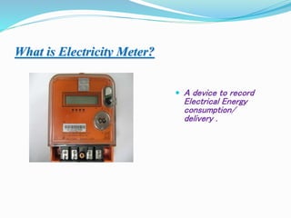
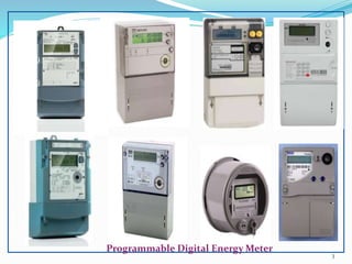
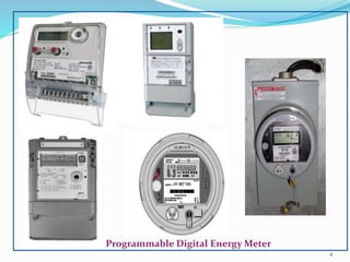
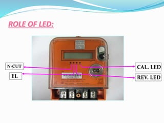
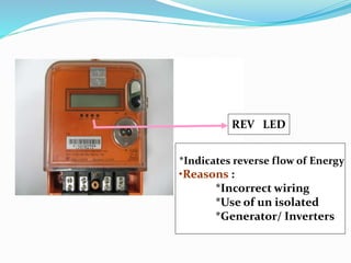
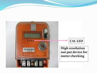
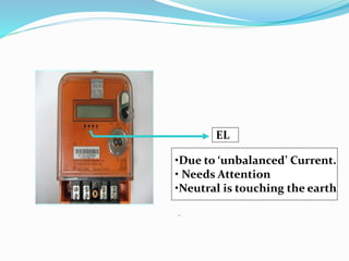
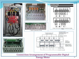
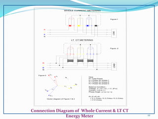
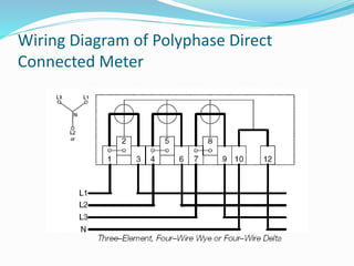
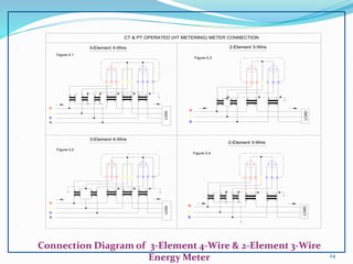
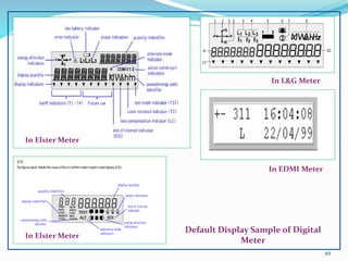
The document discusses electricity meters and their operation. It begins by defining an electricity meter as a device that records electrical energy consumption or delivery. It then discusses the specifications and advantages of programmable digital meters over mechanical meters, including their wider measurement range and resistance to external influences. The document also covers the roles of LED indicators on meters and various meter wiring configurations and connections.
Smart Meter's are a part of Smart Grid,which display the consumption of electricity to end use customer as well as communicate to the utility side for demand side management.
Now in day to day life we have seen that every thing is in digitilized form so this this presentation is ol about the evolution of meter into automatic meter with many technologies.
Its quiet intresting topic and very vast topic too.
Power Theft Identification and Monitoring using GSM moduleAshishPanchdhar1
developed the system were we are using Arduino Atmega328 and current sensors and GSM module attached to every pole. The current sensor keeps the track of amount of current pass through it. When this supply reaches to other end of the pole than the current sensor available at pole 2 will measure the current receive and gives the reading to the Arduino Atmega328. Then the Arduino compares the current readings to the previous readings and if the supply is not approximately equal than the Atmega328 trigger the GSM module. Then the GSM module will send the SMS to the distributor that the amount of current received is not approximately equal and there is some illegal action occurred in the section from pole 1 to pole 2. This will help the distributor to overcome the losses and where the losses will be take place and the theft of the electricity
Power Quality Improvement Using A DVR (Dynamic Voltage Restorer)
ABSTRACT
Power quality is one of major problems in the today’s scenario. It has become important with the introduction of complex devices, whose performance is very sensitive to the quality of power supply. Power quality problem is an occurrence developed as a nonstandard voltage, current or frequency that results in a failure of end use equipment. Some of the major problems dealt here is the power sag and swell. This paper describes the effectiveness of using dynamic voltage restorer (DVR) in order to mitigate voltage sags and swells in low voltage distribution systems. Dynamic Voltage Restorer can provide the most cost effective solution to mitigate voltage sags and swells that is required by customer. The Dynamic Voltage Restorer (DVR) is a rapid, flexible and resourceful solution to power quality problems.
Identification and minimization of HarmonicsMayur Hiwale
In this ppt we will get to know about basic idea of harmonics, types of harmonics , measuring devices and minimizing techniques and also covering the there impact on power system and impact on consumer equipment's.
IOT BASED POWER GRID MONITORING & CONTROL SYSTEMvivatechijri
Energy generation corporations provide electricity to any or all the households via intermediate controlled power transmission hubs referred to as Electricity Grid. Generally issues arise thanks to failure of the electricity grid resulting in black out of a complete space that was obtaining provide from that individual grid. This project aims to resolve this downside victimization IOT because the means that of communication and conjointly coping with numerous alternative problems that a wise system will traumatize to avoid needless losses to the Energy producers.
The slides presents Electronic AC Voltmeter, voltage follower rectifier voltmeter, precision rectifier voltmeter, precision rectifier amplifier voltmeter, voltage to current rectifier voltmeter, current measurement using voltmeter, voltage probe, current probe, temperature probe and RF probe
1.SINGLE PHASE HALF WAVE CONTROLLED CONVERTER WITH RESISTIVEINDUCTIVE LOAD
2 SINGLE PHASE FULLY CONTROLLED CONVERTER WITH RESISTIVEINDUCTIVE LOAD
3 SPEED CONTROL OF 3-PHASE SLIP RING (WOUND ROTOR) INDUCTION MOTOR
4 THYRISTORISED DRIVE FOR DC MOTOR WITH CLOSED LOOP CONTROL
5 THYRISTORISED DRIVE FOR PMDC MOTOR WITH SPEED MEASUREMENT & CLOSED LOOP CONTROL
6 SPEED MEASUREMENT OF PMDC MOTOR WITH CLOSED LOOP CONTROL
7 IGBT USING SINGLE 4 QUADRANT CHOPPER DRIVE FOR PMDC MOTOR WITH SPEED MEASUREMENT AND CLOSED LOOP AND CONTROL
8 SINGLE PHASE CYCLO CONVERTER BASED AC INDUCTION MOTOR CONTROLLER
9 THREE PHASE INPUT THYRISTORISED DRIVE 3HP DC MOTOR WITH CLOSED LOOP CONTROL
10 THREE PHASE INPUT IGBT DRIVE FOR 4 QUADRANT CHOPPER OF 3HP DC MOTOR WITH CLOSED LOOP CONTROL
This presentation will cover the basics and differences between self-contained and transformer or instrument rated meter sites. Also discussed are transformer rated meter forms, test switches and CT's, Blondel's Theorem and why this matters to metering, meter accuracy testing in the field, checking the health of your CT's and PT's, and Site Verification (and not just meter testing).
In this slide I have explained how two watt meters can be used to measure 3 phase power. Some of the added advantage of this method is that we can calculate 3 phase reactive power and power factor of load as well.
Student information management system project report ii.pdfKamal Acharya
Our project explains about the student management. This project mainly explains the various actions related to student details. This project shows some ease in adding, editing and deleting the student details. It also provides a less time consuming process for viewing, adding, editing and deleting the marks of the students.
Industrial Training at Shahjalal Fertilizer Company Limited (SFCL)MdTanvirMahtab2
This presentation is about the working procedure of Shahjalal Fertilizer Company Limited (SFCL). A Govt. owned Company of Bangladesh Chemical Industries Corporation under Ministry of Industries.
Saudi Arabia stands as a titan in the global energy landscape, renowned for its abundant oil and gas resources. It's the largest exporter of petroleum and holds some of the world's most significant reserves. Let's delve into the top 10 oil and gas projects shaping Saudi Arabia's energy future in 2024.
NO1 Uk best vashikaran specialist in delhi vashikaran baba near me online vas...Amil Baba Dawood bangali
Contact with Dawood Bhai Just call on +92322-6382012 and we'll help you. We'll solve all your problems within 12 to 24 hours and with 101% guarantee and with astrology systematic. If you want to take any personal or professional advice then also you can call us on +92322-6382012 , ONLINE LOVE PROBLEM & Other all types of Daily Life Problem's.Then CALL or WHATSAPP us on +92322-6382012 and Get all these problems solutions here by Amil Baba DAWOOD BANGALI
#vashikaranspecialist #astrologer #palmistry #amliyaat #taweez #manpasandshadi #horoscope #spiritual #lovelife #lovespell #marriagespell#aamilbabainpakistan #amilbabainkarachi #powerfullblackmagicspell #kalajadumantarspecialist #realamilbaba #AmilbabainPakistan #astrologerincanada #astrologerindubai #lovespellsmaster #kalajaduspecialist #lovespellsthatwork #aamilbabainlahore#blackmagicformarriage #aamilbaba #kalajadu #kalailam #taweez #wazifaexpert #jadumantar #vashikaranspecialist #astrologer #palmistry #amliyaat #taweez #manpasandshadi #horoscope #spiritual #lovelife #lovespell #marriagespell#aamilbabainpakistan #amilbabainkarachi #powerfullblackmagicspell #kalajadumantarspecialist #realamilbaba #AmilbabainPakistan #astrologerincanada #astrologerindubai #lovespellsmaster #kalajaduspecialist #lovespellsthatwork #aamilbabainlahore #blackmagicforlove #blackmagicformarriage #aamilbaba #kalajadu #kalailam #taweez #wazifaexpert #jadumantar #vashikaranspecialist #astrologer #palmistry #amliyaat #taweez #manpasandshadi #horoscope #spiritual #lovelife #lovespell #marriagespell#aamilbabainpakistan #amilbabainkarachi #powerfullblackmagicspell #kalajadumantarspecialist #realamilbaba #AmilbabainPakistan #astrologerincanada #astrologerindubai #lovespellsmaster #kalajaduspecialist #lovespellsthatwork #aamilbabainlahore #Amilbabainuk #amilbabainspain #amilbabaindubai #Amilbabainnorway #amilbabainkrachi #amilbabainlahore #amilbabaingujranwalan #amilbabainislamabad
Sachpazis:Terzaghi Bearing Capacity Estimation in simple terms with Calculati...Dr.Costas Sachpazis
Terzaghi's soil bearing capacity theory, developed by Karl Terzaghi, is a fundamental principle in geotechnical engineering used to determine the bearing capacity of shallow foundations. This theory provides a method to calculate the ultimate bearing capacity of soil, which is the maximum load per unit area that the soil can support without undergoing shear failure. The Calculation HTML Code included.
Cosmetic shop management system project report.pdfKamal Acharya
Buying new cosmetic products is difficult. It can even be scary for those who have sensitive skin and are prone to skin trouble. The information needed to alleviate this problem is on the back of each product, but it's thought to interpret those ingredient lists unless you have a background in chemistry.
Instead of buying and hoping for the best, we can use data science to help us predict which products may be good fits for us. It includes various function programs to do the above mentioned tasks.
Data file handling has been effectively used in the program.
The automated cosmetic shop management system should deal with the automation of general workflow and administration process of the shop. The main processes of the system focus on customer's request where the system is able to search the most appropriate products and deliver it to the customers. It should help the employees to quickly identify the list of cosmetic product that have reached the minimum quantity and also keep a track of expired date for each cosmetic product. It should help the employees to find the rack number in which the product is placed.It is also Faster and more efficient way.
Explore the innovative world of trenchless pipe repair with our comprehensive guide, "The Benefits and Techniques of Trenchless Pipe Repair." This document delves into the modern methods of repairing underground pipes without the need for extensive excavation, highlighting the numerous advantages and the latest techniques used in the industry.
Learn about the cost savings, reduced environmental impact, and minimal disruption associated with trenchless technology. Discover detailed explanations of popular techniques such as pipe bursting, cured-in-place pipe (CIPP) lining, and directional drilling. Understand how these methods can be applied to various types of infrastructure, from residential plumbing to large-scale municipal systems.
Ideal for homeowners, contractors, engineers, and anyone interested in modern plumbing solutions, this guide provides valuable insights into why trenchless pipe repair is becoming the preferred choice for pipe rehabilitation. Stay informed about the latest advancements and best practices in the field.
6. Specifications of Energy Meter:
Rating :
In : 3x5; Vn : 3x110V(L-L),
In : 3x30(100); Vn : 3x230/400V(L-L),
Starting Current :0.2%
Kwh, KVARH and MD in KW
TOU, 6 Tariff and 6 time zone
6 Month Billing data
RS232C
7. Why Mechanical meters read less?
Influence Parameters
Age
Wear and Tear
Narrow Range
Mounting
Dust and Oil effect
Mechanical Counters
8. Why electronic meters are preferred ?
Wide Range
Low starting current
Less effect of Influence
parameters
More accurate
Tamper proof
14. * In general Phase, current is
used for measurement. However
if neutral Current varies by more
than 10~ 12 % then Neutral
current selected
Good electronic meters have
Current sensors in both the
Phase path, and Neutral path
For Measurement, it chooses
higher * of the two current.
15. Electro-mechanical Meter has
Current sensor only on one wire
All Measurement based on
phase wire current even when
connected to neutral.
16.
17. 1.L and N swapped, load to
Earth
2. L and N swapped, load
partially connected to Earth
19. 3.L and N swapped, l/O swapped,
Load connected to Earth
4.L and N swapped, l/O swapped,
Load partially connected to Earth
20. Wrong wiring, among others things can
result in:
Safety hazards (wires are still live, even
when the main switch is off).
Cause fire (if by mistake, phase and
neutral wires get interchanged)
Wrong Current flow (neighbours current
can flow through your meter)
22. 1 2 3 4 1 5 6 7 8 9 10 11
LOAD
R
Y
B
N
WHOLE CURRENT METERING
Figure-1
N
Y
B
R
4
K L
k
1 2
i
3
K L K
6
k l
5
k
7
L
l
8 9 11
LT CT METERING
LOAD
Figure -2
Figure-3
Vector diagram of Figure-1 & 2
3
I
V 3
1
I
3
1
V 1
2
I2
2
V
Here
P= Total Power
P1= Power for phase-1
P2= Power for phase-2
P3= Power for phase-3
Balance Condition :
Voltage V1-n=V2-n=V3-n = V (P-n)
Current I1=I2=I3 = I
Phase Angle 1=23
P= P1+P2+P3
= V1.I1.Cos1V2.I2.Cos2V3.I3.Cos3
= 3 V.I.Cos
22
Connection Diagram of Whole Current & LT CT
Energy Meter
24. 3-Element 4-Wire
Figure-3.1
3
1 2
N
R
Y
B
v
V
u
v
u
U V U
v
u k
U V K L
l
11
8 9
6 7
4 5
LOAD
k
l
k
K L K L
l
CT & PT OPERATED (HT METERING) METER CONNECTION
3-Element 4-Wire
Figure-3.2
3
1 2
N
R
Y
B
v
u
U V
v
u k
U V K L
l
11
8 9
6 7
4 5
LOAD
k
l
k
K L K L
l
Y
B
R
2
v
u
v
u k
U V U V K
1
k l
i
L K L
7
5
3 8 9
LOAD
Figure-3.3
2-Element 3-Wire
Y
B
R
2
k
K
1
k l
i
L K L
7
5
3 8 9
LOAD
Figure-3.4
2-Element 3-Wire
v
V
u
v
u
U V U
v
u
U V
24
Connection Diagram of 3-Element 4-Wire & 2-Element 3-Wire
Energy Meter
28. Proper connection of 3-Element 4-Wire Energy Meter
R
B
N
Y
2
1
LOAD
5
3 4 7
6 9
8 11
k l k l k l
K L K L K L
U V
u v
U V
u v
U V
u v
CONNECTION CIRCUIT OF METER VECTOR DIAGRAM
Fig.-5-1
Voltage RED Phase open circuited
B
N
Y
R
U
u
V
v
U
u
V
v
LOAD
2
U
u
V
v
K
k
1
L
l
3
K
k
4 5 9
7
L
l k
6
K L
l
8 11
B
N
Y
R
U
u
V
v
U
u
V
v
LOAD
2
U
u
V
v
K
k
1
L
l
3
K
k
4 5 9
7
L
l k
6
K L
l
8 11
V 3
3
I
3
1
I
2
V
2
I
2
Similar for Yellow & Blue phase
V 3
3
I
3
1
V
2
V
2
I
2
Current RED Phase open circuited
V 3
3
I
3
1
I
1
1
V
2
V
2
I
2
CALCULATION
P= P1+P2+P3
= V1.I1.Cos1V2.I2.Cos2V3.I3.Cos3
= 3 V.I.Cos
Here
P= Total Power
P1= Power for phase-1
P2= Power for phase-2
P3=Power for phase-3
V1-n,V2-n ,V3-n = Phase voltage
1,2,3 = Phase angle between V & I
Balance Condition :
V1-n=V2-n =V3-n =V (p-n)
I1=I2 =I3 =I
1 =2 =3 =
P= 3.V.I. Cos
PF=2.V.I. Cos
CF=1.5
PF= P1+P2+P3
= 0V2.I2.Cos2V3.I3.Cos3
= 2 V.I.Cos
PF=2.V.I. Cos
CF=1.5
PF= P1+P2+P3
= 0V2.I2.Cos2V3.I3.Cos3
= 2 V.I.Cos
Balance Condition :
V1=V2 =V3 =V
I1=I2 =I3 =I
1 =2 =3 =
Balance Condition :
V1=V2 =V3 =V
I1=I2 =I3 =I
1 =2 =3 =
Similar for Yellow & Blue phase
Fig.-5-2
Fig.-5-3
FAULT ANALYSIS OF 3-ELEMENT 4-WIRE METERING
P= Total power in proper connection
= 3 V.I.Cos
PF=2 V.I.Cos
Correction Factor(CF)= P
PF
CF= 3 V.I.Cos2 V.I.Cos
28
Faulty Connection Analysis of 3-Element 4-Wire Energy Meter
29. Fig.-5-6
V
Fig.-5-5
Fig.-5-4
V
V
B
N
R
Y
U
u
Y
N
B
R
U
u
Y
N
B
R
U
u
Voltage Red and Blue Phase exchanged
V
v
v v
V
u
U
u
U
k
l
k
K L K
1 2 3 4
l
k
l
K
L L
6
5 7 8 9
LOAD
11
Current Red Phase incorrectly poled
Voltage Red Phase incorrectly poled
V
v
V
v
U
u
U
u v k
K L
l
K
k
1 2 3 4
V
v
V
v
U
u
U
u v k
K L
l
K
k
1 2 3 4
K
L
l k
L
l
6
5 7 8 9
LOAD
11
K
L
l k
L
l
6
5 7 8 9
LOAD
11
PF =P1+P2+P3
= V3.I1.Cos(120°+1)+V2.I2.Cos2
V1.I3.Cos(120°-3)
= V.I Cos(120°+)+Cos
Cos(120°-)
= 0
Similar for Yellow & Blue phase
PF =P2+P3-P1
= V2.I2.Cos2V3.I3.Cos3
-V1.I1.Cos(180°+1)
= V2.I2.Cos2V3.I3.Cos3-V1.I1.Cos1
= V.I.Cos
PF =P2+P3-P1
= V2.I2.Cos2V3.I3.Cos3
-V1.I1.Cos(180°+1)
= V2.I2.Cos2V3.I3.Cos3-V1.I1.Cos1
= V.I.Cos
PF =V.I. Cos
I3
V 3
3
3
V 1
2
CF=
PF =0
1
1
I
I2
2
V
PF =V.I. Cos
CF=3
CF=3
-V
I3
3
V
3
1
1
I
2
3
I
3
V
3
1
V
-I1
2
1
1
I2
V2
I2
V2
CONNECTION CIRCUIT OF METER VECTOR DIAGRAM CALCULATION
Balance Condition :
V1=V2 =V3 =V
I1=I2 =I3 =I
1 =2 =3 =
Balance Condition :
V1=V2 =V3 =V
I1=I2 =I3 =I
1 =2 =3 =
Balance Condition :
V1=V2 =V3 =V
I1=I2 =I3 =I
1 =2 =3 =
FAULT ANALYSIS OF 3-ELEMENT 4-WIRE METERING
29
Faulty Connection Analysis of 3-Element 4-Wire Energy Meter
37. History of Energy Meter:
The first accurate, recording electricity
consumption meter was a D.C(Direct Current).
Dr. Hermann Aron, who patented it in 1883 in the
General Electric Company.
It is commercially introduced into Great Britain from
1888.
Aron's meter recorded the total energy used over
time, and showed it on a series of clock dials.
38. History of Energy Meter:
The first specimen of the AC kilowatt-hour meter produced
on the basis of Hungarian Ottó Bláthy's patent and named
after him was presented by the Ganz Works at the
Frankfurt Fair in the autumn of 1889, and the first
induction kilowatt-hour meter was already marketed by the
factory at the end of the same year. These were the first
alternating-current wattmeters, known by the name of
Bláthy-meters.
39. History of Electromechanical Energy Meter:
The most common type of electricity meter is the Thomson
or electromechanical induction watt-hour meter, invented
by Elihu Thomson in 1888.
The electromechanical induction meter operates by
counting the revolutions of an aluminum disc which is
made to rotate at a speed proportional to the power. The
number of revolutions is thus proportional to the energy
usage.
It consumes a small amount of power, typically around 2
watts
40. Classification of energy meter:
According to their Specification:
Energy Meter
Single phase Three phase and
three wire
Three phase and
four wire
1.Single phase: reference voltage: 220V
2. Three phase and three wire: reference voltage: 3X100/110V
3. Three phase and four wire: reference voltage:
3X57.7V/100/110V, 3X220V/380/415V
41. Classification of energy meter:
According to their connection:
Energy Meter
Connection through
transformers
Direct connection
1.Current from connection through transformers: 3X0.3 (1.2) A,
3X0.5 (2) A, 3X1.5 (6) A, and 3X5 (6) A, etc.
2. Current from direct connection: 3X5 (20) A, 3X10 (40) A, and
3X30 (100) A, etc
42. Classification of energy meter:
According to their Measuring Accuracy:
Energy Meter
Watt-hour Var-hour
1.Watt-hour accuracy class: 0.2S, 0.5S, 0.5, 1.0,2.0.
2.Var-hour accuracy class: 0.2S, 0.5S, 0.5, 1.0,2.0.
43. Classification of energy meter:
According to purposes, energy meters can be divided
into:
Single phase energy meter
Three-phase watt-hour energy meter
Three-phase var-hour energy meter
Maximum demand meter
Multi-rate energy meter (time-based)
Multifunctional watthour meter
Copper loss meter
Iron loss meter
Prepayment energy meter
44. What is power?
Electric power is the rate at which electrical energy is
transferred by an electric circuit. That means
Power = Energy(Work done) / Time
The SI unit of power is the watt(named after the
scientist James Watt) that means one joule per second.
1 Watt = 1 Joule / Second.
A 100 watt light bulb is a device that converts 100 joules of
electrical energy into 100 joules of electromagnetic
radiation (light) every second.
45. What is power?
The electric power in watts produced by an electric
current I consisting of a charge of Q coulombs every t
seconds passing through an electric potential (voltage)
difference of V is
where
Q is electric charge in coulombs
t is time in seconds
I is electric current in amperes
V is electric potential or voltage in volts
46. What is Energy?
The term energy defines the amount of power consumed
/delivered over the period. That means..
Energy = Power x Time.
1 kilo-watt hour = the energy delivered by 1000 watts of
power over over a one hour time period. That means…
Energy = Power x Time
= (1000 Joules/Second) x (3600 Seconds)
= 3,600,000 Joules = 3.6 million Joules!
That's a lot of Joules! So you see that kilo-watt hours is a
much better unit for large amounts of energy a one hour
time period.
52. Benefits of Phasor Analysis:
Provide visual verification of errors in service
wiring
Minimize or eliminate the need to use instrument
meters (volt, amp, phase angle)
Facilitate the detection and trouble-shooting of:
Cross-phased wires
Wrong application
Wrong CT and PT polarity
53. Energy meter testing Procedure:
1.First Process:
With the help of a duly calibrated standard lamp of 1000 watt:-
A 1000-watt lamp if energized for one hour would consume one
unit of electrical energy.
Switch off all electrical lamps/appliances, etc., in your house.
Percentage error =
(energy registered by the meter – true energy) × 100
true energy
54. Energy meter testing Procedure:
2.Second Process:
With the help of Meter constant which is indicated in the Meter
Body. e.g. X impulses /kWh i.e. X impulses per unit i.e. X times
blinking of LED installed on meter for 1 unit consumption of
electrical energy.
We may cross check this meter constant by actually counting the
blinking of LED e.g. one unit should be registered by the meter in
3200 impulses i.e. 3200 times blinking of LED or ½ unit should be
registered in 1600 impulses or ¼ unit should be registered in 800
impulses and so on. If meter constant indicated on the meter
matches with your actual impulse count/number of blinks of LED, it
means that the meter is running ok.
55. Energy meter testing Procedure:
3.Third Process:
With the help of a Voltmeter, Ammeter, Switch and a Stop
Watch:- Connect the Switch (SW), Voltmeter (V) and Ammeter
(A) as shown in the following circuit diagram:
S.L
N.O
Energy Meter
Initial Reading
(kWh) (X)
Energy
Meter
Final
Reading
(kWh) (Y)
V
(Volts)
I
(Amps)
T
(Seconds)
Energy by
calculation =
Vlt/1000x3600
(kWh)
Energy Meter
Reading (X)-(Y)
(kWh)
56. Energy meter testing Procedure:
4.Fourth Process:
With the help of a Meter Testing Set:
PWS-2.3,
PEWM-3CF,
PRS-1.3,
EDI
57. IEC Standards for meter testing:
S.L
N.O
IEC Standard N.O. Purpose
01. IEC 62053-11 For electromechanical meters
02. IEC 62053-21 For electronic meters
03. IEC 62052-11 For general requirements, tests & test conditions of
metering equipments.
61. `
MD Manager
`
MD Manager
`
Web Browser
`
Web Browser
MultiDrive Servers
PowerSignature
Servers
MultiDrive
Comm. Servers
MD COM API
RADIO
DIRECT
P
L
C
/
D
L
C
G
P
R
S
/
E
D
G
E
/
3
G
GSM
Database Servers
PLC / DLC
Concentrator
RS232 / RS485
Convertor
TCP/UDP
Total Connectivity
64. Frequently Answer Question:
Q. Why are electricity bills getting inflated after replacement of old
electromechanical meters by new electronic meters by the utilities?
A : 01: Energy consumed by the consumer is actually high.
02. New meter is working satisfactorily but the wiring to meter,
which was done earlier as per old electromechanical meter was
not correct.