Metal Film Metrology AWgage-200
•
0 likes•94 views

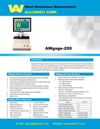
AWgage-200 measures sheet resistance in ohms per square or milliohms per square. If specific resistivity is known, the thickness of the deposited film layer can be computed from the sheet resistance. The choice of measurement data is easily get in the software. AWgage-200 can accommodate 200mm (8") wafers as well as the standard 6" wafers without any hardware change

Recommended
Recommended
More Related Content
What's hot
What's hot (12)
Viewers also liked
Viewers also liked (15)
Similar to Metal Film Metrology AWgage-200
Similar to Metal Film Metrology AWgage-200 (20)
More from Peter Chen
More from Peter Chen (20)
Recently uploaded
Recently uploaded (20)
Metal Film Metrology AWgage-200
- 1. Sheet Resistance Measurement ALLLWIN21 CORP. AWgage-200 Introduction AWgage-200 measures sheet resistance in ohms per square or milliohms per square. If specific resistivity is known, the thickness of the deposited film layer can be computed from the sheet resistance. The choice of measurement data is easily get in the software. AWgage-200 can accommodate 200mm (8") wafers as well as the standard 6" wafers without any hardware change. AWgage-200 Key Features 30 years proven Eddy Sheet Resistance Measurement technology. Non-contact Sheet Resistance Measurement. 1mΩ/square to 19,990Ω/square sheet resistance measurement range. 100Å to 270kÅ Metal Film Thickness range. Touch Screen Monitor GUI and PC w/ Advanced Allwin21 software. Wafer carriage travel programmed with internal encoder step motor , without encoder disk. Consistent wafer-to-wafer process cycle repeatability. Small footprint and energy efficient. Made in U.S.A. AWgage-200 Specifications • Perform odd number of site tests: 1 to 9 points • Highly Conductive or Metal Sheet Resistance 1 to 1,999 mΩ/square 1 to 1,999 Ω/square 10 to 19,990 Ω/square • Highly Conductive or Metal Film Thickness Minimum: 100 Ångström Maximum: Proportional to resistivity. Maximum for a resistivity of 2.7 µΩ-cm is 270 k Å (27 µm) • Sheet Resistance Repeatability Total repeatability is the standard deviation (σ) percent of mean value(X),1 count. Range s/X (±%) 1 to 100 mW/sq; W/sq 1 100 to 500 mW/sq; W/sq 2 500 to 1000 mW/sq; W/sq 4 1000 to 1,999 mW/sq; W/sq 6 1,999 to 5,000 W/sq Consult Factory 5000 to 10,000 W/sq Consult Factory 10,000 to 15,000 W/sq Consult Factory E-mail: sales@allwin21.com Website: www.allwin21.com Introduction AWgage-200 Configuration Main Frame Wafer Carriage (2”-6”) Measurement Head RF Tank Circuit board Pentium® class computer board Main control board Motor control board. Two USB Ports Two Extra DB9 Ports 15–inch touch screen GUI Allwin21 Corp proprietary software package. Mouse & keyboard . USB Flash Drive with AW Software backup. CE Certification (Optional) Mgage 200, Mgage 300, M-gage 200, M-gage 300,Sheet Resistant measurement, Metrology, Tencor M-Gage 300,Tencor M-Gage 200, sheet resistance, sheet resistance Measurement, Semiconductor Equipment, Semiconductor metrology Equipment, KLA-Tencor, Tencor
- 2. Sheet Resistance Measurement ALLLWIN21 CORP. AWgage-200 Software Key Features The AWgage-200 system is controlled by menu commands from the control software. This software allows a great deal of flexibility and control of the Allwin21 system. The AWgage-200 control software features the following: • Automated calibration of all subsystems from within the control software. This allows faster and easier calibration, leading to enhanced process results. The AWgage-200 allows calibration of the ohm and milliohm measurements within the software for maximum performance and accuracy. This provides a much easier and faster method to calibrate the instrument than by adjusting pots on the back of the traditional Sheet Resistance Measurement Instrument. • The SOFTWARE can compensate for where the flat is on the carriage to locate the test points. • It features a recipe editor to create and edit recipes to fully automate the processing of wafers on the Allwin21 system. • Validation of the recipe so improper points will be revealed. • Storage of multiple recipes, process data and calibration files so that process and calibration results can be maintained and compared over time. • Passwords provide security for the system, recipe editing, diagnostics, calibration and setup functions. • Simple and easy to use menu screens which allow an automatic cycle to be easily defined and executed. • Troubleshooting features which allow engineers and service personnel to activate individual subassemblies and functions. AWgage-200 Facilities Requirements • Instrument needs to be on a hard/solid surface. • The room temperature should be close to 23° C for the greatest measurement accuracy. • Avoid environments with high concentrations of particulates, especially abrasives such as glass and silicon dust. • Power : 50/60Hz, Single Phase, 110/220VAC, 2 Amps • Weight and Dimensions: 44 LBs ; 11 inch (W) X 18 inch (D) X 22 inch (H) AWgage-200 Measurement Processes • Turn on the power to the AWgage-200. Allow 30 minutes for warming up. • Select an existing recipe or create a new recipe. • When The carriage is in the loading position, place the wafer on the carriage between the four locator blocks. The wafer will be centered over the circular platform that rotates the wafer. • Manual Mode: Press the MAN/AUTO button, so the LED is off. Momentarily press the START/STANDBY button. The carriage will move the wafer under the measurement head to the first point in the measurement sequence. For multi-point measurements--press START/STANDBY once for each point in the measurement sequence. The wafer will be advanced to the next point. When the measurement sequence is complete the carriage will move to the right until the wafer is out from under the measurement head in the loading/unloading position. The wafer can be removed from the carriage after it has reached this position. • Automatic Mode: Press the MAN/AUTO button on the AWgage-200 control panel until the LED comes on. Press the START/STANDBY button. The entire measurement sequence will be performed without further operator intervention. When the sequence is complete, the wafer will be moved to the unloading position. • PC Screen Mode: Press the “Start Test” button at the Process Screens (for Engineer or Production) to test the wafer that is on the wafer carriage, using the selected recipe. The entire measurement sequence will be performed without further operator intervention. When the sequence is complete, the wafer will be moved to the unloading position. • All data measurements are recorded in the computer for later retrieval, inspection and, if desired, a print-out of the measured points can be printed on an external printer. Recipe Editor Start Test Testing Data Allwin21 Corp. Address: 220 Cochrane Circle, Morgan Hill,CA95037, U.S.A. Tel.: +1-408-778-7788 Fax: +1-408-904-7168 Email: sales@allwin21.com All specification and information here are subject to change without notice and cannot be used for purchase and facility plan.