Download to read offline

![9
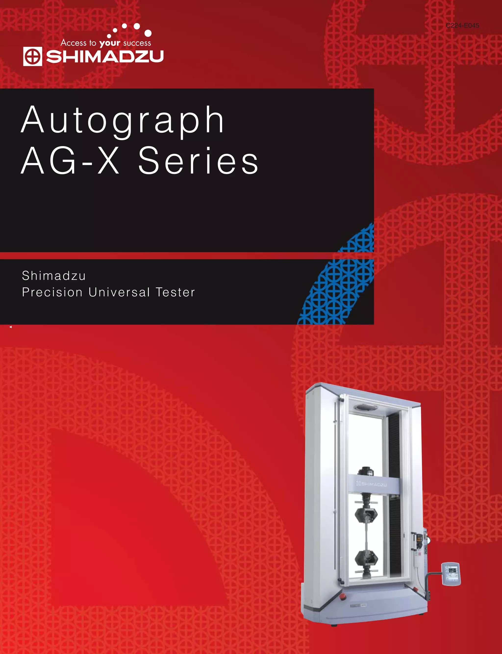
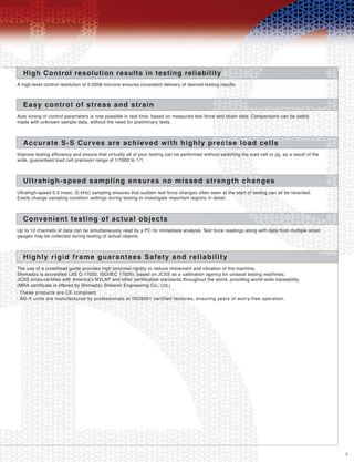
1. Perform high-efficiency, continuous testing because of fast data searches and one-touch method selection.
Intuitive machine operation
Start testing in just one step after frequently-used methods are recorded in the Quick
Method List.
•
2. Visual wizard guidance ensures trouble-free entry of method settings
Complicated method settings can be entered using the Method Wizard, which
provides an overview of the entire process.
•
Setting entry guidance, linked to online help, is available in each window.•
Easy-to-understand illustrations are used in the [Testing], [Specimen] and
[Data Processing] windows, greatly simplifying the entry of settings.
•
Data processing settings (single software: plastic material)
Specimen quantity and size settings window
General data processing items are prepared in advance.
Simply press buttons on the figure to select settings.
1
Illustrations are displayed for each specimen shape. A single glance shows
which dimensions should be entered.
3
In addition to manual input, dimensions can also be set via [Excel batch reading]
or [Automatic input via calipers].
4
Additional, non-dimensional information can also be entered for each specimen.5
Illustrations change according to the test mode and specimen material.
Use a key word or date to quickly search for saved test results and Method files.
Also, easily call up files using previews of reports and lists of settings.
2
Use a key word or date to quickly search for saved test results and Method files. Also,
easily call up files using previews of reports and lists of settings.
•
Search conditions
1
Search results
Summary preview
2
3
4
5](https://image.slidesharecdn.com/a9379296-1022-4ee0-80b1-e1aabe0349d1-150320023629-conversion-gate01/85/C224-E045-AG-X-Series-Ctlg-9-320.jpg)
![10
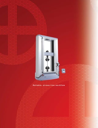
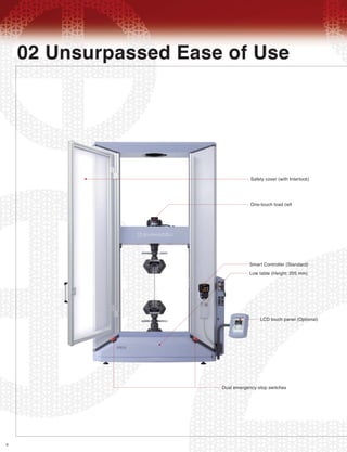
03 Quest for Convenience
Receive data quickly
Speed, dimension, and report information can be entered quickly and directly from the main window
using the [Quick Panel].
1.
Generate detailed reports
Richly expressive report creation includes free positioning of report elements and a wealth of web-compatible output functions.
Advanced navigation system with learning functions2.
AG-X is equipped with a Navigation Bar that shows only the functions required for a selected situation. This allows
you to efficiently perform continuous testing using simple, straightforward procedures and by pressing large,
easy-to-read buttons.
AG-X is also equipped with a "Learning function" that records user actions for each situation and adds
frequently-used functions to the Navigation Bar. This means that the more you use the machine, the better the "fit"
is to your unique operation style, effectively speeding up your workflow.
•
Functions include re-test, file synthesis, as well as specimen insertion, addition and
order changes in any position.
3.
Re-test: A portion of a batch test can be retested, and the prior test results replaced.•
Report Designer allows flexible layout•
Extra lot tests: batches (lots) can be added, increasing the total number of tests.•
A variety of setting changes are possible before and after testing. Specimens can be inserted in
any position or added to only a specific batch, and the specimen order can be changed after
testing is completed.
•
Create reports that include test data, charts, photographs and logos.
Freely change report layout and element sizes.
Use detailed settings for each element's font, color and ruled lines.
Reports can be output in PDF, Microsoft Word, Excel and HTML formats.•
Output reports created with Report Designer in a wide variety of useful formats.
(Charts and tables with ruled lines cannot be output in Word and HTML.)
After export, use your everyday software to customize the report.
WebPlus function (option)•
Installing the WebPlus option on your server PC allows reanalysis and printing
via Internet Explorer, even on a PC not equipped with TRAPEZIUM X.](https://image.slidesharecdn.com/a9379296-1022-4ee0-80b1-e1aabe0349d1-150320023629-conversion-gate01/85/C224-E045-AG-X-Series-Ctlg-10-320.jpg)
![12
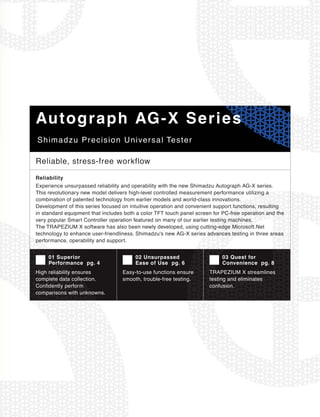
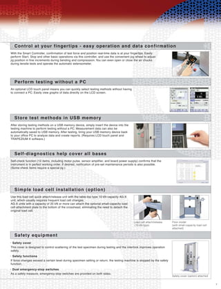
Accessories Lineup
Tensile tests
Combine grips and extensometers with the testing machine.
Grips•
Used to grip the sample, a wide variety is available to accommodate different specimen types and test force amounts.
DVE series non-contact video extensometer
DVE series extensometers use two cameras to provide a wide measurement range and high measurement precision.
(Elongation is measured via the PC monitor screen. Elongation measurement in an environmentally-sealed chamber is also possible.)
GL50 mm Maximum measurement range 30 mm
Absolute precision of indicated value ±3 μm (JIS B7741 Class 1)
Relative precision ± 1%
GL20 mm Maximum measurement range 140 mm
Absolute precision of indicated value ±6 μm (JIS B7741 Class 2)
Relative precision ±1%
Extensometers•
Extensometers improve elongation measurement accuracy.
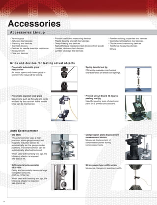
Accessories
[ Experience the range of possibilities available with this full-featured system ]
Non-shift wedge type grips <MWG> Applications: Plastics, Metals, Wood
Grip
capacity
Standard grip face
Grip face Clearance (mm) Grip width (mm) Grip length (mm)
Upper grip capacity
(kg)
Part No.
250kN
100kN
50kN
20kN
5kN
File teeth for
flat specimens
0 to 8.5
0 to 7
0 to 7
0 to 7
0 to 7
50
40
40
25
25
75
55
55
55
55
33
10
9.5
3.6
3.6
343-07979-12
346-52791-12
346-52791-11
346-52653-12
346-52653-11
Pneumatic flat grips <PFG> Applications: Rubber, Plastics, Textiles, Cloth, Paper
*1 Grips with foot-valve units and crosshead–linked control functions are also available.
*2 Grips can be opened and closed via the Smart Controller when using the crosshead-linked control kit.
Grip
capacity
External dimensions (mm)
W L (upper/lower)
Grip width (mm) Clearance (mm) Upper grip capacity
(kg)
Kit No.*1, *2
10kN
5kN
1kN
50N
154
154
102
64
268.5 / 278.5
224 / 235
163 / 174
118 / 135
60
60
50
35
0 to 10
0 to 6
0 to 6
0 to 6
—
5.7
1.7
0.4
346-53916-XX
346-53849-XX
364-53848-XX
346-53847-XX
Screw type flat grips <SCG> Applications: Rubber, Plastics, Textiles, Cloth, Paper
Grip
capacity
Standard grip face
Grip face Clearance (mm) Grip width (mm) Grip length (mm)
Upper grip capacity
(kg)
Part No.
5kN
1kN
50N
File teeth
Flat
0 to 16
0 to 15
0 to 14
60
50
35
50
30
25
2
0.7
0.3
345-52326-04
346-52327-04
346-52328-04
Strain gauge type one-touch extensometer <SSG-H Series>
SSG-H series extensometers conform to JIS B7741 Class 0.5 and JIS K7161 (SSG 50-10SH only).
They can be attached using just one touch.
* Calibration cables (for SGI) are included with each kit.
* Precision is JIS B7741 Class 0.5 or Class 1, depending on the conditions.
Model
SSG25-50H
SSG25-100H
SSG50-10H
SSG50-10SH
Gauge length (mm)
25
25
50
50
Measuring range (mm)
12.5 5.25 2.5 1.24
25 12.5 5 2.5
5 2.5 1 0.5
5 2.5 1 0.5
Kit No.
346-53875-23
346-53875-24
346-53875-51
346-53875-56
Non-shift wedge type grips
Screw type flat grips
Pneumatic flat grips](https://image.slidesharecdn.com/a9379296-1022-4ee0-80b1-e1aabe0349d1-150320023629-conversion-gate01/85/C224-E045-AG-X-Series-Ctlg-12-320.jpg)
![16
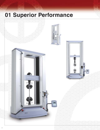
Specifications
[ Table-Top AG-X ]
1. Model Name
AG-10N / 20N / 50N / 100NX AG-500 / 1k / 2kNX AG-5kNX
Table-Top AG-X
AG-10kNX AG-20kN / 50kNXD
10N / 20N / 50N / 100N 500 / 1k / 2kN 5kN
Direct, high-precision, constant-rate strain control using non-backlash precision ball-screw drive
Automatic calibration Standard-precision type: Tensile and compression forces calibration
High-precision type: Choose from calibration of tensile force, compression force, or both tensile and compression forces
Free step-less setting
0.0005 ~ 1000
±0.1%
Maximum load capacity for all speeds
Optical encoder measurement, digital display
1500
420
1200
Not available
Within ± 0.5% of displayed test force (for 1/100 to 1/1000 of load cell rated capacity)
Within ± 0.3% of displayed test force (for 1/1 to 1/100 of load cell rated capacity)
Conforms to JIS B7721 Class 0.5, EN 10002-2 Grade 0.5, ISO 7500-1 Class 0.5, BS1610 Class 0.5,
DIN51221 Class 1, and ASTM E4*3
Within ± 1% of displayed test force (for 1/1 to 1/1000 of the load cell rated capacity)
Conforms to JIS B7721 Class 1, EN 10002-2 Grade 1, ISO 7500-1 Class 1, BS1610 Class 1, DIN51221 Class 1,
and ASTM E4*3
• Automatic reading of load cell properties
• Fine adjustment of crosshead position
• Test force and stroke display
• External analog output (2 channels)
• External analog input (2 channels)
• External digital input (2 channels)
• Internal amps - 4 ports
(one is used for test force and another for analog input)
• USB interface (for PC) / Host interface (for USB memory)
• Recorder output (optional)
• Dataletty output (optional)
• Pneumatic grip interlock operation (optional)
• Automatic test force and strain control (with auto tuning)
• Test force auto zero / auto calibration
• Break detection / auto return
• Crosshead speed free setting / cycle count display
• Stress value display / extensometer value display
• Soft limit detection / self diagnostics
If only optional LCD touch panel is used:
• Single testing control / Cycle testing control /
Control of testing conforming to standards
• PEAK and BREAK values display / Crosshead speed pre-setting
• Method internal memory file (20 files)
• Japanese/English switchover / S-S curve display
Within ± 1% of displayed test force (for 1/1 to 1/500 of load cell rated capacity)
Conforms to JIS B7721 Class 1, EN 10002-2 Grade 1, ISO 7500-1 Class 1, BS1610 Class 1, DIN51221 Class 1,
and ASTM E4*3
10kN 20kN / 50kN
Max. 1150 mm (850 mm) Max. 1150 mm (850 mm) Max. 1150 mm (780 mm) Max. 1150 mm (600 mm)
Max. 1060 mm
(655 mm): 20 kN
(605 mm): 50 kN
For 10 N/ 20 N/ 50 N/100 N For 500/ 1 k/2 kN For 5 kN For 10 kN For 20 kN/50 kN
For 10 N/ 20 N/ 50 N/100 N For 500/ 1 k/2 kN For 5 kN
Standard tool set, instruction manuals, limit warning labels
Housed in main frame
For 10 kN For 20 kN/50 kN
955 x 579 x 1606
2. Capacity
3. Loading Method
4. Test Force
Measurement
5. Crosshead Speed Range
(mm/min)
6. Crosshead Speed Precision*1
8. Crosshead Speed and Allowed Test Force
9. Crosshead-Table Clearance (mm)
(Tensile stroke) *2
10. Effective Test Width (mm)
11. Crosshead Position
Detection
Measurement and
display methods
12. Data Capture Rate
Maximum Return Speed
Test force calibration
Precision
Standard-precision unit
1/1000
High-precision unit 1/1000
1/500
14. Frame Rigidity (kN/mm)
15. Standard Functions
16. Accessories
Load cell
17. Dimensions
(approx.)
W x D x H
(mm)
CAL. cable
Others
Main frame
Measurement controller
Smart Controller
Precision Within ±0.1% of indicated value, however, ±0.01 mm when indicated value is below 10 mm
5000Hz
300kHz
42
777 x 510 x 1580
120
0.025μm 0.0208μm
80 x 50 x 250 (attached on right side of main unit - detachable)
Crosshead speed precision is calculated using crosshead transfer amount within a specified period of time for the crosshead speed of 0.5 mm/min
to 500 mm/min under normal conditions.
*1:
Tensile stroke is the value used when attaching the MWG (non-shift wedge type) grips.
Stroke can be extended.
Values under 5 kN are with SCG (screw type flat) grips attached.
*2:
JIS B7721, EN 10002-2, ISO 7500-1, and ASTM E4 standards recommend re-verification after installation of testing machine.*3:
In conformity with CE Mark regulation*4:
Displayed units are by default expressed in SI system.
Other unit system is selectable as Metric or English imperial by a keystroke.
*5:
Software is available in several languages (English,Spanish,Chinese,Japanese etc.)*6:
* Values in this catalog have been measured based on separately-approved test standards.
7. Position Control Resolution
13. Data Sampling Rate](https://image.slidesharecdn.com/a9379296-1022-4ee0-80b1-e1aabe0349d1-150320023629-conversion-gate01/85/C224-E045-AG-X-Series-Ctlg-16-320.jpg)
![18
Specifications
[ Floor Type AG-X ]
1. Model Name
Floor Type AG-X
AG-250kN / 300kNX
Direct, high-precision, constant-rate strain control using non-backlash precision ball-screw drive
Automatic calibration Standard-precision type: Tensile and compression forces calibration
High-precision type: Choose from calibration of tensile force, compression force, or both tensile and compression forces
Free step-less setting
0.0005 to 1000 0.0005 to 500
±0.1%
300
Maximum load capacity for all speeds
Optical encoder measurement, digital display
1200
595
600
Within ± 0.5% of displayed test force (for 1/100 to 1/1000 of load cell rated capacity)
Within ± 0.3% of displayed test force (for 1/1 to 1/100 of load cell rated capacity)
Conforms to JIS B7721 Class 0.5, EN 10002-2 Grade 0.5, ISO 7500-1 Class 0.5,
BS1610 Class 0.5, DIN51221 Class 1, and ASTM E4*3
Within ± 1% of displayed test force (for 1/1 to 1/1000 of load cell rated capacity)
Conforms to JIS B7721 Class 1, JIS B7733 Class 1, EN 10002-2 Grade 1, ISO 7500-1 Class 1, BS1610 Class 1,
DIN51221 Class 1, and ASTM E4*4
• Automatic reading of load cell properties
• Fine adjustment of crosshead position
• Test force and stroke display
• External analog output (2 channels)
• External analog input (2 channels)
• External digital input (2 channels)
• Internal amps - 4 ports
(one is used for test force and another for analog input)
• USB interface (for PC) / Host interface (for USB memory)
• Recorder output (optional)
• Dataletty output (optional)
• Pneumatic grip interlock operation (optional)
• Automatic test force and strain control (with auto tuning)
• Test force auto zero / auto calibration
• Break detection / auto return
• Crosshead speed free setting / cycle count display
• Stress value display / extensometer value display
• Soft limit detection / self diagnostics
If only optional LCD touch panel is used:
• Single testing control / Cycle testing control /
Control of testing conforming to standards
• PEAK and BREAK values display / Crosshead speed pre-setting
• Method internal memory file (20 files)
• Japanese/English switchover / S-S curve display
Within ± 1% of displayed test force (for 1/1 to 1/500 of the load cell rated capacity)
Conforms to JIS B7721 Class 1, EN 10002-2 Grade 1, ISO 7500-1 Class 1, BS1610 Class 1, DIN51221 Class 1,
and ASTM E4*3
250kN / 300kN
Within ±0.5% of displayed test force
(for 1/1 to 1/250 of load cell rated capacity)
AG-100kNX
100kN
AG-20kN / 50kNXD
20kN / 50kN
Max. 1265 mm
(850 mm): 20 kN
(800 mm): 50 kN
Max. 1250 mm (760 mm) Max. 1440 mm (600 mm)
0.0005 ~ 250mm/min : 300kN
250mm/min ~ : 250kN
For 20 kN/50 kNX
For 20 kN/50 kNX
For 100 kNX
For 100 kNX
For 250 kN/300 kN
For 250 kN/300 kN
Standard tool set, instruction manuals, limit warning label
Housed in main frame
1186 x 752 x 2414
2. Capacity
3. Loading Method
4. Test Force
Measurement
5. Crosshead Speed Range
(mm/min)
6. Crosshead Speed Precision*1
8. Crosshead Speed and Allowed Test Force
9. Crosshead-Table Clearance (mm)
(Tensile stroke) *2
10. Effective Test Width (mm)
11. Crosshead Position
Detection
Measurement and
display methods
12. Data Capture Rate
Maximum Return Speed
Test force calibration
Precision
Standard-precision unit
1/1000
High-precision unit 1/1000
(1/250 for 250 kN and 300 kN models)
1/500
14. Frame Rigidity (kN/mm)
15. Standard Functions
16. Accessories
Load cell
17. Dimensions
(approx.)
W x D x H
(mm)
CAL. cable
Others
Main frame
Measurement controller
Smart Controller
Precision Within ±0.1% of indicated value, but ±0.01 mm when the indicated value is below 10 mm
5000Hz
400175
1186 x 752 x 2164
80 x 50 x 250 (attached on right side of main unit - detachable)
Crosshead speed precision is calculated using crosshead transfer amount within a specified period of time for the crosshead speed of 0.5 mm/min
to 500 mm/min under normal conditions.
*1:
Tensile stroke is the value used when attaching the MWG (non-shift wedge type) grips.
Stroke can be extended.
Values under 5 kN are with SCG (screw type flat) grips attached.
*2:
JIS B7721, EN 10002-2, ISO 7500-1, and ASTM E4 standards recommend re-verification after installation of testing machine.*3:
* Values in this catalog have been measured based on separately-approved test standards.
0.0208μm 0.0104μm
In conformity with CE Mark regulation*4:
Displayed units are by default expressed in SI system.
Other unit system is selectable as Metric or English imperial by a keystroke.
*5:
Software is available in several languages (English,Spanish,Chinese,Japanese etc.)*6:
7. Position Control Resolution
13. Data Sampling Rate 300kHz](https://image.slidesharecdn.com/a9379296-1022-4ee0-80b1-e1aabe0349d1-150320023629-conversion-gate01/85/C224-E045-AG-X-Series-Ctlg-18-320.jpg)
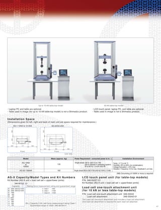
![19
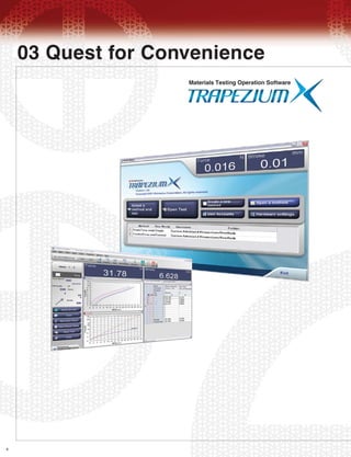
Installation Space
20 kN, 50 kN floor model 100 kN floor model
• Laptop PC and table are optional. • LCD touch panel, laptop PC, and table are optional.
• Wide frame series
(Dimensions given for left, right and back of main unit are space required
for maintenance.)
AG-X Capacity/Model Types and Kit Numbers
Kit Number (AG-X unit + load cell set + upper/lower joints)
LCD touch panel unit (for floor models)
P/N: 346-55227-52
Extensions to the main unit [Table-top models and floor models]
Model
AG-20kN / 50kNX
AG-100kNX
AG-250kN / 300kNX
620
800
920
Three phase 200 to 230 V 50 to 60 Hz 5 kVA (1.2 kW)
Three phase 200 to 230 V 50 to 60 Hz 7 kVA (2.0 kW)
Three phase 200 to 230 V 50 to 60 Hz 7.5 kVA (2.5 kW)
Temp.: 5 °C to 40 °C
Humidity: 20% to 80% (no condensation)
Voltage fluctuation: ±10% max.
Vibration: Frequency 10 Hz max. Amplitude 5 μm max.
Mass (approx. kg) Power requirement - consumed power is in ( ) Installation Environment
00 : 300kN
01 : 250kN
02 : 100kN
03 : 50kN
04 : 20kN
346-567XX-X1
600600
4-M20
LEVEL BOLTS
1186
928
500
752600
Speed Range (mm/min)
Part Number
0.00005 mm/min to 1000 mm/min
(250 kN and 300 kN models are limited to 500 mm/min.)
345-50522
Ultralow-speed models
(NB) Grounding of 100W or more is required.
Models with wider effective test widths (975 mm, 1100 mm and 1375 mm) than
the standard type (595 mm) are also available for testing large-size actual ob-
ject specimens. (Floor models only.)
• Reinforced yoke series
Use this series when conducting tests between the crosshead and yoke.
• Ultralow-speed crosshead model
The crosshead speed range can be widened to include extremely low speeds.
• Large capacity series
With maximum capacities of 500 kN, 600 kN and 1000 kN, these
models are used for large-capacity testing in heavy-industry fields
such as steel, construction, and shipbuilding. They can be
customized upon request.
• Extended column models
Models with extended columns are useful for testing materials
requiring long tensile strokes. (Clearance between the yoke and
table is extended 250 mm, 500 mm, or 750 mm.)
• High-speed return models
Table-top models less than 2 kN can be equipped with drives that
have a return speed of 3000 mm/min, and a crosshead speed
range of 0.001 mm/min to 2500 mm/min.
AG-20 kNX to 300 kN
Front Unit: mm
5 : Class 1 1/500
6 : Class 1 1/1000
7 : Class 0.5 1/1000
(Ex.) Capacity 100 kN, test force measurement rating Class 1
Guaranteed range of 1/500: 346-56702-51
Capacity Testing force measurement rating and guaranteed range](https://image.slidesharecdn.com/a9379296-1022-4ee0-80b1-e1aabe0349d1-150320023629-conversion-gate01/85/C224-E045-AG-X-Series-Ctlg-19-320.jpg)


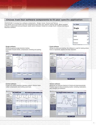
The document summarizes testing equipment from Shimadzu, including their new AG-X Precision Universal Tester series. The AG-X series focuses on reliability, easy operation, and convenient support functions. It delivers high-precision measurement performance through patented technologies and innovations. The user-friendly interface and software allow intuitive operation and efficient workflow. A variety of accessories are also available for different testing applications.


