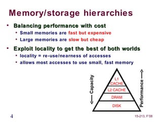
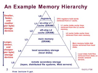
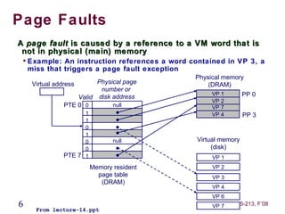
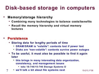
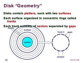
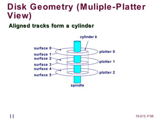
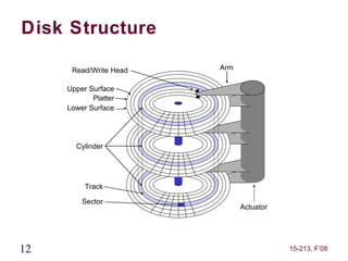
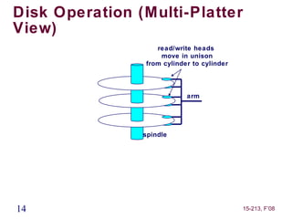
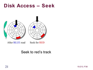
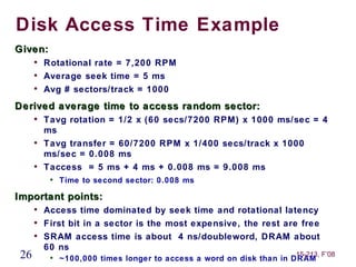
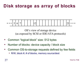
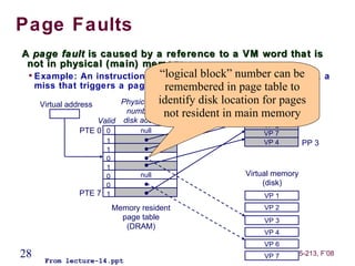
15-213
          “ The course that gives CMU its Zip!”


           Disk-based Storage
              Oct. 23, 2008
        Topics
             
                 Storage technologies and trends
             
                 Locality of reference
             
                 Caching in the memory hierarchy


lecture-17.ppt
Announcements
Exam next Thursday
     
         style like exam #1: in class, open book/notes, no electronics


 2                                                             15-213, F’08
Disk-based storage in computers

    Memory/storage hierarchy
        
            Combining many technologies to balance costs/benefits
        
            Recall the memory hierarchy and virtual memory
            lectures


    3                                                     15-213, F’08
Memory/storage hierarchies

        Balancing performance with cost
        
            Small memories are fast but expensive
        
            Large memories are slow but cheap

        Exploit locality to get the best of both worlds
        
            locality = re-use/nearness of accesses
        
            allows most accesses to use small, fast memory


                                        Capacity


                                                               Performance
    4                                                        15-213, F’08
An Example Memory Hierarchy
 Smaller,                        L0:
  faster,                          registers     CPU registers hold words
   and                                           retrieved from L1 cache.
 costlier                      L1: on-chip L1
(per byte)                       cache (SRAM)        L1 cache holds cache lines
                                                     retrieved from the L2 cache
 storage                                             memory.
 devices                 L2:       off-chip L2
                                 cache (SRAM)              L2 cache holds cache lines
                                                           retrieved from main memory.

                   L3:           main memory
 Larger,                           (DRAM)
                                                                  Main memory holds disk
 slower,                                                          blocks retrieved from local
    and                                                           disks.
 cheaper                  local secondary storage
             L4:
(per byte)                      (local disks)                           Local disks hold files
  storage                                                               retrieved from disks on
 devices                                                                remote network
                                                                        servers.
       L5:              remote secondary storage
              (tapes, distributed file systems, Web servers)

  5     From lecture-9.ppt
                                                                            15-213, F’08
Page Faults
A page fault is caused by a reference to a VM word that is
 not in physical (main) memory
    
        Example: An instruction references a word contained in VP 3, a
        miss that triggers a page fault exception
                                                   Physical memory
         Virtual address       Physical page           (DRAM)
                                number or
                                                        VP 1         PP 0
                         Valid disk address
                                                        VP 2
                     PTE 0 0        null                VP 7
                         1                              VP 4         PP 3
                         1
                         0
                         1
                         0          null            Virtual memory
                         0                               (disk)
                   PTE 7 1                              VP 1
                             Memory resident            VP 2
                               page table               VP 3
                                (DRAM)
                                                        VP 4
                                                        VP 6
6         From lecture-14.ppt
                                                        VP 7     15-213, F’08
Disk-based storage in computers

    Memory/storage hierarchy
        
            Combining many technologies to balance costs/benefits
        
            Recall the memory hierarchy and virtual memory
            lectures



    Persistence
        
            Storing data for lengthy periods of time
             
                 DRAM/SRAM is “volatile”: contents lost if power lost
             
                 Disks are “non-volatile”: contents survive power outages
        
            To be useful, it must also be possible to find it again
            later
             
                 this brings in many interesting data organization,
                 consistency, and management issues
                   
                       take 18-746/15-746 Storage Systems 
    7        
                 we’ll talk a bit about file systems next             15-213, F’08
What’s Inside A Disk Drive?
                     Spindle
               Arm                                  Platters

    Actuator


                                            Electronics


          SCSI
        connector
                               Image courtesy of Seagate Technology

8                                                     15-213, F’08
Disk Electronics
                   Just like a small
                   computer – processor,
                   memory, network iface

                      • Connect to disk

                      • Control processor

                      • Cache memory
                      • Control ASIC

                      • Connect to motor


9                                 15-213, F’08
Disk “Geometry”
Disks contain platters, each with two surfaces
Each surface organized in concentric rings called
  tracks
Each track consists of sectors separated by gaps
     tracks
              surface
                                    track k   gaps


              spindle


                                    sectors
10                                             15-213, F’08
Disk Geometry (Muliple-Platter
View)
Aligned tracks form a cylinder
                         cylinder k


        surface 0
                                      platter 0
        surface 1
        surface 2
                                      platter 1
        surface 3
        surface 4
                                      platter 2
        surface 5

                     spindle


11                                                15-213, F’08
Disk Structure

      Read/Write Head   Arm

     Upper Surface
            Platter
     Lower Surface


       Cylinder


          Track

         Sector
                              Actuator


12                                       15-213, F’08
Disk Operation (Single-Platter
View)
The disk
surface                         The read/write head
spins at a                      is attached to the end
fixed                           of the arm and flies over
rotational rate                  the disk surface on
                                a thin cushion of air


                    spindle
                      spindle
                  spindle
                  spindle


                                By moving radially, the
                                arm can position the
                                read/write head over any
                                track


13                                                15-213, F’08
Disk Operation (Multi-Platter
View)
                   read/write heads
                    move in unison
                from cylinder to cylinder


                            arm


                spindle


14                                          15-213, F’08
Disk Structure - top view of
single platter

          Surface organized into tracks

          Tracks divided into sectors


15                                        15-213, F’08
Disk Access


      Head in position above a track


16                                     15-213, F’08
Disk Access


     Rotation is counter-clockwise


17                                   15-213, F’08
Disk Access – Read


      About to read blue sector


18                                15-213, F’08
Disk Access – Read


 After BLUE read


            After reading blue sector


19                                      15-213, F’08
Disk Access – Read


 After BLUE read


            Red request scheduled next


20                                       15-213, F’08
Disk Access – Seek


 After BLUE read   Seek for RED


            Seek to red’s track


21                                15-213, F’08
Disk Access – Rotational
Latency


 After BLUE read   Seek for RED   Rotational latency


            Wait for red sector to rotate around


22                                                     15-213, F’08
Disk Access – Read


 After BLUE read   Seek for RED   Rotational latency   After RED read


            Complete read of red


23                                                          15-213, F’08
Disk Access – Service Time
Components


 After BLUE read   Seek for RED   Rotational latency   After RED read

            Seek
            Rotational Latency
            Data Transfer

24                                                          15-213, F’08
Disk Access Time
Average time to access a specific sector
  approximated by:
     
         Taccess = Tavg seek + Tavg rotation + Tavg transfer
Seek time (Tavg seek)
     
         Time to position heads over cylinder containing target
         sector
     
         Typical Tavg seek = 3-5 ms
Rotational latency (Tavg rotation)
     
         Time waiting for first bit of target sector to pass under r/w
         head
     
         Tavg rotation = 1/2 x 1/RPMs x 60 sec/1 min
          
              e.g., 3ms for 10,000 RPM disk

Transfer time (Tavg transfer)
     
         Time to read the bits in the target sector
25   
                                                         15-213, F’08
         Tavg transfer = 1/RPM x 1/(avg # sectors/track) x 60
Disk Access Time Example
Given:
      
          Rotational rate = 7,200 RPM
      
          Average seek time = 5 ms
      
          Avg # sectors/track = 1000
Derived average time to access random sector:
      
          Tavg rotation = 1/2 x (60 secs/7200 RPM) x 1000 ms/sec = 4
          ms
      
          Tavg transfer = 60/7200 RPM x 1/400 secs/track x 1000
          ms/sec = 0.008 ms
      
          Taccess = 5 ms + 4 ms + 0.008 ms = 9.008 ms
           
               Time to second sector: 0.008 ms

Important points:
      
          Access time dominated by seek time and rotational latency
      
          First bit in a sector is the most expensive, the rest are free
      
          SRAM access time is about 4 ns/doubleword, DRAM about
          60 ns
 26        
                                                                     15-213, F’08
               ~100,000 times longer to access a word on disk than in DRAM
Disk storage as array of blocks


    …5        6 7            12                          23   …
                    OS’s view of storage device
            (as exposed by SCSI or IDE/ATA protocols)

     Common “logical block” size: 512 bytes

     Number of blocks: device capacity / block size

     Common OS-to-storage requests defined by few fields
     
         R/W, block #, # of blocks, memory source/dest

27                                                            15-213, F’08
Page Faults
A page fault is caused by a reference to a VM word that is
 not in physical (main) memory
 
     Example: An instruction references block” number can be 3, a
                                “logical a word contained in VP
     miss that triggers a page fault exception in page table to
                                 remembered
      Virtual address                 identify disk location(DRAM)
                            Physical page                     for pages
                                                         Physical memory
                             number or not resident in main memory
                                                              VP 1     PP 0
                      Valid disk address
                                                              VP 2
                  PTE 0 0        null                         VP 7
                     1                                       VP 4        PP 3
                     1
                     0
                     1
                     0          null                    Virtual memory
                     0                                       (disk)
               PTE 7 1                                       VP 1
                         Memory resident                     VP 2
                           page table                        VP 3
                            (DRAM)
                                                             VP 4
                                                             VP 6
28     From lecture-14.ppt
                                                             VP 7    15-213, F’08
In device, “blocks” mapped to physical store


         Disk Sector
 (usually same size as block)


 29                                     15-213, F’08
Physical sectors of a single-
surface disk


30                              15-213, F’08
LBN-to-physical for a single-
surface disk
                           4              5

            3              16          17
                                                        6
                15             28    29            18
                     27                       30
                               40 41
       2             39                42                    7
           14                                           19
                26
                   38                       43 31
                      37                44 32
                25
       1   13             36           45               20   8
                               4    46
                     24        7          33
                12             35    34      21
            0                          22               9
                           23

                          11            10

31                                                               15-213, F’08
Disk Capacity

Capacity: maximum number of bits that can be stored
     
         Vendors express capacity in units of gigabytes (GB), where
         1 GB = 10 9 Bytes (Lawsuit pending! Claims deceptive
         advertising)


Capacity is determined by these technology factors:
     
         Recording density (bits/in): number of bits that can be
         squeezed into a 1 inch linear segment of a track
     
         Track density (tracks/in): number of tracks that can be
         squeezed into a 1 inch radial segment
     
         Areal density (bits/in2 ): product of recording and track
         density


32                                                               15-213, F’08
Computing Disk Capacity
Capacity =       (# bytes/sector) x (avg. # sectors/track) x
                 (# tracks/surface) x (# surfaces/platter) x
                 (# platters/disk)
Example:
     
         512 bytes/sector
     
         1000 sectors/track (on average)
     
         20,000 tracks/surface
     
         2 surfaces/platter
     
         5 platters/disk


Capacity = 512 x 1000 x 80000 x 2 x 5
            = 409,600,000,000
              = 409.6 GB
33                                                         15-213, F’08
Looking back at the hardware
     CPU chip
            register file

                            ALU


                                   main
        bus interface
                                  memory


34                                    15-213, F’08
Connecting I/O devices: the I/O
Bus
     CPU chip
            register file

                            ALU
                                  system bus     memory bus


                                        I/O                     main
        bus interface
                                       bridge                  memory


                                       I/O bus                Expansion slots for
                                                              other devices such
            USB             graphics               disk       as network adapters
          controller        adapter              controller

        mousekeyboard       monitor
                                                   disk
35                                                                   15-213, F’08
Reading from disk (1)
CPU chip
                                   CPU initiates a disk read by writing a READ
        register file
                                   command, logical block number, number of
                                   blocks, and destination memory address to a
                        ALU
                                   port (address) associated with disk controller


                                                          main
   bus interface
                                                         memory


                                                 I/O bus


        USB             graphics            disk
      controller        adapter           controller

   mousekeyboard        monitor
                                                        disk
 36                                                                   15-213, F’08
Reading from disk (2)
CPU chip
                                   Disk controller reads the sectors and
        register file
                                   performs a direct memory access (DMA)
                                   transfer into main memory
                        ALU


                                                      main
   bus interface
                                                     memory


                                              I/O bus


        USB             graphics          disk
      controller        adapter         controller

   mousekeyboard        monitor
                                           disk
 37                                                             15-213, F’08
Reading from disk (3)
CPU chip
                                   When the DMA transfer completes, the
        register file
                                   disk controller notifies the CPU with an
                                   interrupt (i.e., asserts a special “interrupt”
                        ALU
                                   pin on the CPU)


                                                            main
   bus interface
                                                           memory


                                                   I/O bus


        USB             graphics              disk
      controller        adapter             controller

   mousekeyboard        monitor
                                               disk
 38                                                                       15-213, F’08

Mem hierarchy

  • 1.
    15-213 “ The course that gives CMU its Zip!” Disk-based Storage Oct. 23, 2008 Topics  Storage technologies and trends  Locality of reference  Caching in the memory hierarchy lecture-17.ppt
  • 2.
    Announcements Exam next Thursday  style like exam #1: in class, open book/notes, no electronics 2 15-213, F’08
  • 3.
    Disk-based storage incomputers  Memory/storage hierarchy  Combining many technologies to balance costs/benefits  Recall the memory hierarchy and virtual memory lectures 3 15-213, F’08
  • 4.
    Memory/storage hierarchies  Balancing performance with cost  Small memories are fast but expensive  Large memories are slow but cheap  Exploit locality to get the best of both worlds  locality = re-use/nearness of accesses  allows most accesses to use small, fast memory Capacity Performance 4 15-213, F’08
  • 5.
    An Example MemoryHierarchy Smaller, L0: faster, registers CPU registers hold words and retrieved from L1 cache. costlier L1: on-chip L1 (per byte) cache (SRAM) L1 cache holds cache lines retrieved from the L2 cache storage memory. devices L2: off-chip L2 cache (SRAM) L2 cache holds cache lines retrieved from main memory. L3: main memory Larger, (DRAM) Main memory holds disk slower, blocks retrieved from local and disks. cheaper local secondary storage L4: (per byte) (local disks) Local disks hold files storage retrieved from disks on devices remote network servers. L5: remote secondary storage (tapes, distributed file systems, Web servers) 5 From lecture-9.ppt 15-213, F’08
  • 6.
    Page Faults A pagefault is caused by a reference to a VM word that is not in physical (main) memory  Example: An instruction references a word contained in VP 3, a miss that triggers a page fault exception Physical memory Virtual address Physical page (DRAM) number or VP 1 PP 0 Valid disk address VP 2 PTE 0 0 null VP 7 1 VP 4 PP 3 1 0 1 0 null Virtual memory 0 (disk) PTE 7 1 VP 1 Memory resident VP 2 page table VP 3 (DRAM) VP 4 VP 6 6 From lecture-14.ppt VP 7 15-213, F’08
  • 7.
    Disk-based storage incomputers  Memory/storage hierarchy  Combining many technologies to balance costs/benefits  Recall the memory hierarchy and virtual memory lectures  Persistence  Storing data for lengthy periods of time  DRAM/SRAM is “volatile”: contents lost if power lost  Disks are “non-volatile”: contents survive power outages  To be useful, it must also be possible to find it again later  this brings in many interesting data organization, consistency, and management issues  take 18-746/15-746 Storage Systems  7  we’ll talk a bit about file systems next 15-213, F’08
  • 8.
    What’s Inside ADisk Drive? Spindle Arm Platters Actuator Electronics SCSI connector Image courtesy of Seagate Technology 8 15-213, F’08
  • 9.
    Disk Electronics Just like a small computer – processor, memory, network iface • Connect to disk • Control processor • Cache memory • Control ASIC • Connect to motor 9 15-213, F’08
  • 10.
    Disk “Geometry” Disks containplatters, each with two surfaces Each surface organized in concentric rings called tracks Each track consists of sectors separated by gaps tracks surface track k gaps spindle sectors 10 15-213, F’08
  • 11.
    Disk Geometry (Muliple-Platter View) Alignedtracks form a cylinder cylinder k surface 0 platter 0 surface 1 surface 2 platter 1 surface 3 surface 4 platter 2 surface 5 spindle 11 15-213, F’08
  • 12.
    Disk Structure Read/Write Head Arm Upper Surface Platter Lower Surface Cylinder Track Sector Actuator 12 15-213, F’08
  • 13.
    Disk Operation (Single-Platter View) Thedisk surface The read/write head spins at a is attached to the end fixed of the arm and flies over rotational rate the disk surface on a thin cushion of air spindle spindle spindle spindle By moving radially, the arm can position the read/write head over any track 13 15-213, F’08
  • 14.
    Disk Operation (Multi-Platter View) read/write heads move in unison from cylinder to cylinder arm spindle 14 15-213, F’08
  • 15.
    Disk Structure -top view of single platter Surface organized into tracks Tracks divided into sectors 15 15-213, F’08
  • 16.
    Disk Access Head in position above a track 16 15-213, F’08
  • 17.
    Disk Access Rotation is counter-clockwise 17 15-213, F’08
  • 18.
    Disk Access –Read About to read blue sector 18 15-213, F’08
  • 19.
    Disk Access –Read After BLUE read After reading blue sector 19 15-213, F’08
  • 20.
    Disk Access –Read After BLUE read Red request scheduled next 20 15-213, F’08
  • 21.
    Disk Access –Seek After BLUE read Seek for RED Seek to red’s track 21 15-213, F’08
  • 22.
    Disk Access –Rotational Latency After BLUE read Seek for RED Rotational latency Wait for red sector to rotate around 22 15-213, F’08
  • 23.
    Disk Access –Read After BLUE read Seek for RED Rotational latency After RED read Complete read of red 23 15-213, F’08
  • 24.
    Disk Access –Service Time Components After BLUE read Seek for RED Rotational latency After RED read Seek Rotational Latency Data Transfer 24 15-213, F’08
  • 25.
    Disk Access Time Averagetime to access a specific sector approximated by:  Taccess = Tavg seek + Tavg rotation + Tavg transfer Seek time (Tavg seek)  Time to position heads over cylinder containing target sector  Typical Tavg seek = 3-5 ms Rotational latency (Tavg rotation)  Time waiting for first bit of target sector to pass under r/w head  Tavg rotation = 1/2 x 1/RPMs x 60 sec/1 min  e.g., 3ms for 10,000 RPM disk Transfer time (Tavg transfer)  Time to read the bits in the target sector 25  15-213, F’08 Tavg transfer = 1/RPM x 1/(avg # sectors/track) x 60
  • 26.
    Disk Access TimeExample Given:  Rotational rate = 7,200 RPM  Average seek time = 5 ms  Avg # sectors/track = 1000 Derived average time to access random sector:  Tavg rotation = 1/2 x (60 secs/7200 RPM) x 1000 ms/sec = 4 ms  Tavg transfer = 60/7200 RPM x 1/400 secs/track x 1000 ms/sec = 0.008 ms  Taccess = 5 ms + 4 ms + 0.008 ms = 9.008 ms  Time to second sector: 0.008 ms Important points:  Access time dominated by seek time and rotational latency  First bit in a sector is the most expensive, the rest are free  SRAM access time is about 4 ns/doubleword, DRAM about 60 ns 26  15-213, F’08 ~100,000 times longer to access a word on disk than in DRAM
  • 27.
    Disk storage asarray of blocks …5 6 7 12 23 … OS’s view of storage device (as exposed by SCSI or IDE/ATA protocols)  Common “logical block” size: 512 bytes  Number of blocks: device capacity / block size  Common OS-to-storage requests defined by few fields  R/W, block #, # of blocks, memory source/dest 27 15-213, F’08
  • 28.
    Page Faults A pagefault is caused by a reference to a VM word that is not in physical (main) memory  Example: An instruction references block” number can be 3, a “logical a word contained in VP miss that triggers a page fault exception in page table to remembered Virtual address identify disk location(DRAM) Physical page for pages Physical memory number or not resident in main memory VP 1 PP 0 Valid disk address VP 2 PTE 0 0 null VP 7 1 VP 4 PP 3 1 0 1 0 null Virtual memory 0 (disk) PTE 7 1 VP 1 Memory resident VP 2 page table VP 3 (DRAM) VP 4 VP 6 28 From lecture-14.ppt VP 7 15-213, F’08
  • 29.
    In device, “blocks”mapped to physical store Disk Sector (usually same size as block) 29 15-213, F’08
  • 30.
    Physical sectors ofa single- surface disk 30 15-213, F’08
  • 31.
    LBN-to-physical for asingle- surface disk 4 5 3 16 17 6 15 28 29 18 27 30 40 41 2 39 42 7 14 19 26 38 43 31 37 44 32 25 1 13 36 45 20 8 4 46 24 7 33 12 35 34 21 0 22 9 23 11 10 31 15-213, F’08
  • 32.
    Disk Capacity Capacity: maximumnumber of bits that can be stored  Vendors express capacity in units of gigabytes (GB), where 1 GB = 10 9 Bytes (Lawsuit pending! Claims deceptive advertising) Capacity is determined by these technology factors:  Recording density (bits/in): number of bits that can be squeezed into a 1 inch linear segment of a track  Track density (tracks/in): number of tracks that can be squeezed into a 1 inch radial segment  Areal density (bits/in2 ): product of recording and track density 32 15-213, F’08
  • 33.
    Computing Disk Capacity Capacity= (# bytes/sector) x (avg. # sectors/track) x (# tracks/surface) x (# surfaces/platter) x (# platters/disk) Example:  512 bytes/sector  1000 sectors/track (on average)  20,000 tracks/surface  2 surfaces/platter  5 platters/disk Capacity = 512 x 1000 x 80000 x 2 x 5 = 409,600,000,000 = 409.6 GB 33 15-213, F’08
  • 34.
    Looking back atthe hardware CPU chip register file ALU main bus interface memory 34 15-213, F’08
  • 35.
    Connecting I/O devices:the I/O Bus CPU chip register file ALU system bus memory bus I/O main bus interface bridge memory I/O bus Expansion slots for other devices such USB graphics disk as network adapters controller adapter controller mousekeyboard monitor disk 35 15-213, F’08
  • 36.
    Reading from disk(1) CPU chip CPU initiates a disk read by writing a READ register file command, logical block number, number of blocks, and destination memory address to a ALU port (address) associated with disk controller main bus interface memory I/O bus USB graphics disk controller adapter controller mousekeyboard monitor disk 36 15-213, F’08
  • 37.
    Reading from disk(2) CPU chip Disk controller reads the sectors and register file performs a direct memory access (DMA) transfer into main memory ALU main bus interface memory I/O bus USB graphics disk controller adapter controller mousekeyboard monitor disk 37 15-213, F’08
  • 38.
    Reading from disk(3) CPU chip When the DMA transfer completes, the register file disk controller notifies the CPU with an interrupt (i.e., asserts a special “interrupt” ALU pin on the CPU) main bus interface memory I/O bus USB graphics disk controller adapter controller mousekeyboard monitor disk 38 15-213, F’08

Editor's Notes

  • #4 *
  • #8 *
  • #10 No copyright needed – scanned by Erik Riedel.
  • #16 Goal: Show the inefficeincy of current disk requests. Conveyed Ideas: Rotational latency is wasted time that can be used to service tasks Background Information: None. Slide Background: None. Kill text and arrows
  • #17 Goal: Show the inefficeincy of current disk requests. Conveyed Ideas: Rotational latency is wasted time that can be used to service tasks Background Information: None. Slide Background: None. Kill text and arrows
  • #18 Goal: Show the inefficeincy of current disk requests. Conveyed Ideas: Rotational latency is wasted time that can be used to service tasks Background Information: None. Slide Background: None. Kill text and arrows
  • #19 Goal: Show the inefficeincy of current disk requests. Conveyed Ideas: Rotational latency is wasted time that can be used to service tasks Background Information: None. Slide Background: None. Kill text and arrows
  • #20 Goal: Show the inefficeincy of current disk requests. Conveyed Ideas: Rotational latency is wasted time that can be used to service tasks Background Information: None. Slide Background: None. Kill text and arrows
  • #21 Goal: Show the inefficeincy of current disk requests. Conveyed Ideas: Rotational latency is wasted time that can be used to service tasks Background Information: None. Slide Background: None. Kill text and arrows
  • #22 Goal: Show the inefficeincy of current disk requests. Conveyed Ideas: Rotational latency is wasted time that can be used to service tasks Background Information: None. Slide Background: None. Kill text and arrows
  • #23 Goal: Show the inefficeincy of current disk requests. Conveyed Ideas: Rotational latency is wasted time that can be used to service tasks Background Information: None. Slide Background: None. Kill text and arrows
  • #24 Goal: Show the inefficeincy of current disk requests. Conveyed Ideas: Rotational latency is wasted time that can be used to service tasks Background Information: None. Slide Background: None. Kill text and arrows
  • #25 Goal: Show the inefficeincy of current disk requests. Conveyed Ideas: Rotational latency is wasted time that can be used to service tasks Background Information: None. Slide Background: None. Kill text and arrows