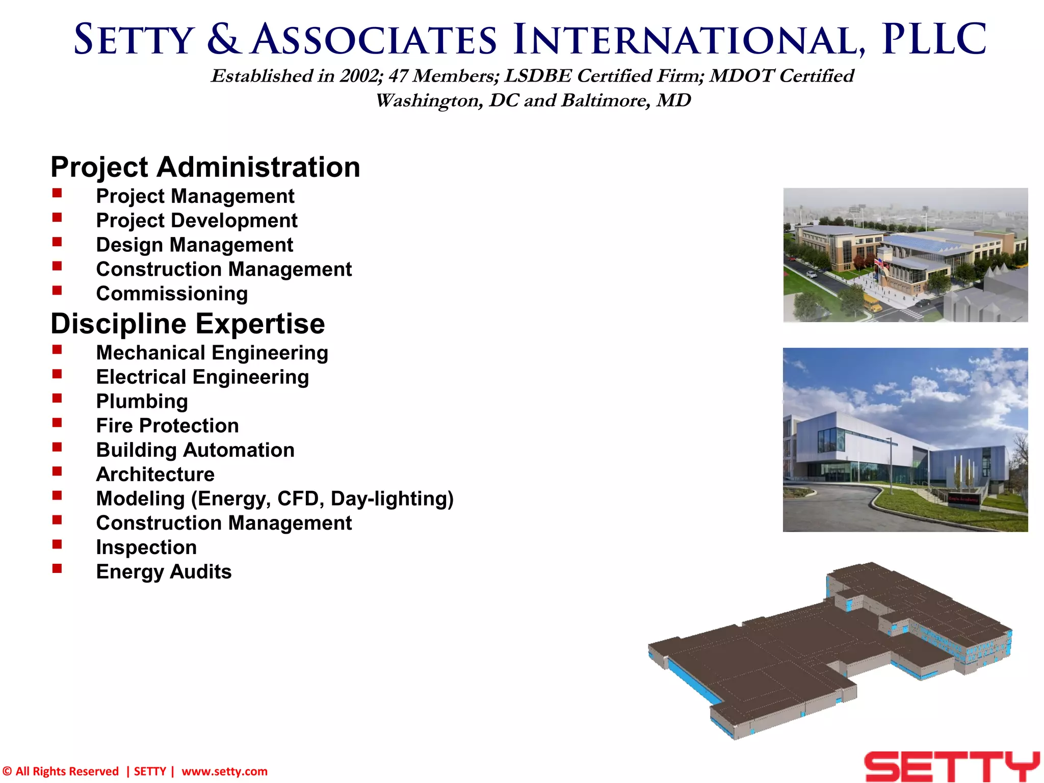
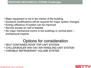
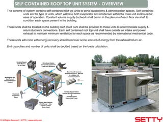
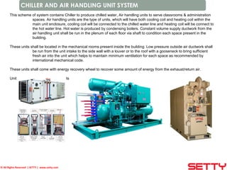
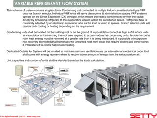
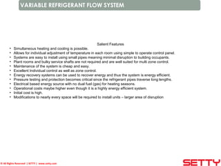
© All Rights Reserved | SETTY | www.setty.com
Setty & Associates International, PLLC
Established in 2002; 47 Members; LSDBE Certified Firm; MDOT Certified
Washington, DC and Baltimore, MD
Project Administration
 Project Management
 Project Development
 Design Management
 Construction Management
 Commissioning
Discipline Expertise
 Mechanical Engineering
 Electrical Engineering
 Plumbing
 Fire Protection
 Building Automation
 Architecture
 Modeling (Energy, CFD, Day-lighting)
 Construction Management
 Inspection
 Energy Audits
© All Rights Reserved | SETTY | www.setty.com
PROPOSED MECHANICAL SYSTEMS Challenges
• Major equipment is not in the interior of the building.
• Ductwork modifications will be required for major system changes.
• Energy efficiency of system can be improved
• Service access on roof is feasible
• No major mechanical rooms in the buildings or central plant –
architectural impacts
Options for consideration
• SELF CONTAINED ROOF TOP UNIT SYSTEM
• CHILLER/BOILER With VAV AIR HANDLING UNIT SYSTEM
• VARIABLE REFRIGERANT VOLUME SYSTEM
© All Rights Reserved | SETTY | www.setty.com
SELF CONTAINED ROOF TOP UNIT SYSTEM - OVERVIEW
This scheme of system contains self contained roof top units to serve classrooms & administration spaces. Self contained
units are the type of units, which will have both evaporator and condenser within the main unit enclosure for
ease of operation. Constant volume supply ductwork shall be run in the plenum of each floor via shaft to
condition each space present in the building.
These units shall be located on the building roof. Roof curb shall be provided to these units to accommodate supply &
return ductwork connections. Each self contained roof top unit shall have outside air intake and power
exhaust to maintain minimum ventilation for each space as recommended by international mechanical code.
These units will come with energy recovery wheel to recover some amount of energy from the exhaust/return air.
Unit capacities and number of units shall be decided based on the loads calculation.
© All Rights Reserved | SETTY | www.setty.com
CHILLER AND AIR HANDLING UNIT SYSTEM
This scheme of system contains Chiller to produce chilled water, Air handling units to serve classrooms & administration
spaces. Air handling units are the type of units, which will have both cooling coil and heating coil within the
main unit enclosure, cooling coil will be connected to the chilled water line and heating coil will be connect to
the hot water line. Hot water is produced by condensing boilers. Constant volume supply ductwork from the
air handling unit shall be run in the plenum of each floor via shaft to condition each space present in the
building.
These units shall be located in the mechanical rooms present inside the building. Low pressure outside air ductwork shall
be run from the unit intake to the side wall with a louver or to the roof with a gooseneck to bring sufficient
fresh air into the unit which helps to maintain minimum ventilation for each space as recommended by
international mechanical code.
These units shall come with energy recovery wheel to recover some amount of energy from the exhaust/return air.
Unit capacities and number of units shall be decided based on the loads calculation.
© All Rights Reserved | SETTY | www.setty.com
VARIABLE REFRIGERANT FLOW SYSTEM
This scheme of system contains single outdoor Condensing unit connected to multiple Indoor cassette/ducted type VRF
units via Branch selector. Individual VRF units will serve classrooms & administration spaces. VRF systems
operate on the Direct Expansion (DX) principle, which means the heat is transferred to or from the space
directly by circulating refrigerant to the evaporators located within the conditioned space. Refrigerant flow is
constantly adjusted by an electronic expansion valve as the load is varied in spaces. Branch selector units will
provide both cooling or heating depending on the requirement.
Condensing units shall be located on the building roof or on the ground. It is possible to connect as high as 10 indoor units
to one outdoor unit minimizing the roof area required to accommodate the condensing units. In order to cool a
room heat energy must be removed at a greater rate than it is being introduced. It is possible to incorporate
heat recovery technology that harnesses the unwanted heat from areas that require cooling and either stores
it or transfers it to rooms that require heating.
Dedicated Outside Air System will be installed to maintain minimum ventilation rate per international mechanical code. Unit
shall come with energy recovery wheel to recover some amount of energy from the exhaust/return air.
Unit capacities and number of units shall be decided based on the loads calculation.
© All Rights Reserved | SETTY | www.setty.com
VARIABLE REFRIGERANT FLOW SYSTEM
Salient Features
• Simultaneous heating and cooling is possible.
• Allows for individual adjustment of temperature in each room using simple to operate control panel.
• Systems are easy to install using small pipes meaning minimal disruption to building occupants.
• Plant rooms and bulky service shafts are not required and are well suited for multi zone control.
• Maintenance of the system is cheap and easy.
• Excellent Individual control as well as zone control.
• Energy recovery systems can be used to recover energy and thus the system is energy efficient.
• Pressure testing and protection becomes critical since the refrigerant pipes traverse long lengths.
• Electrical based energy source with no dual fuel (gas) for heating seasons.
• Operational costs maybe higher even though it is a highly energy efficient system.
• Initial cost is high.
• Modifications to nearly every space will be required to install units – larger area of disruption

Mechanical systems

  • 1.
    © All RightsReserved | SETTY | www.setty.com Setty & Associates International, PLLC Established in 2002; 47 Members; LSDBE Certified Firm; MDOT Certified Washington, DC and Baltimore, MD Project Administration  Project Management  Project Development  Design Management  Construction Management  Commissioning Discipline Expertise  Mechanical Engineering  Electrical Engineering  Plumbing  Fire Protection  Building Automation  Architecture  Modeling (Energy, CFD, Day-lighting)  Construction Management  Inspection  Energy Audits
  • 2.
    © All RightsReserved | SETTY | www.setty.com PROPOSED MECHANICAL SYSTEMS Challenges • Major equipment is not in the interior of the building. • Ductwork modifications will be required for major system changes. • Energy efficiency of system can be improved • Service access on roof is feasible • No major mechanical rooms in the buildings or central plant – architectural impacts Options for consideration • SELF CONTAINED ROOF TOP UNIT SYSTEM • CHILLER/BOILER With VAV AIR HANDLING UNIT SYSTEM • VARIABLE REFRIGERANT VOLUME SYSTEM
  • 3.
    © All RightsReserved | SETTY | www.setty.com SELF CONTAINED ROOF TOP UNIT SYSTEM - OVERVIEW This scheme of system contains self contained roof top units to serve classrooms & administration spaces. Self contained units are the type of units, which will have both evaporator and condenser within the main unit enclosure for ease of operation. Constant volume supply ductwork shall be run in the plenum of each floor via shaft to condition each space present in the building. These units shall be located on the building roof. Roof curb shall be provided to these units to accommodate supply & return ductwork connections. Each self contained roof top unit shall have outside air intake and power exhaust to maintain minimum ventilation for each space as recommended by international mechanical code. These units will come with energy recovery wheel to recover some amount of energy from the exhaust/return air. Unit capacities and number of units shall be decided based on the loads calculation.
  • 4.
    © All RightsReserved | SETTY | www.setty.com CHILLER AND AIR HANDLING UNIT SYSTEM This scheme of system contains Chiller to produce chilled water, Air handling units to serve classrooms & administration spaces. Air handling units are the type of units, which will have both cooling coil and heating coil within the main unit enclosure, cooling coil will be connected to the chilled water line and heating coil will be connect to the hot water line. Hot water is produced by condensing boilers. Constant volume supply ductwork from the air handling unit shall be run in the plenum of each floor via shaft to condition each space present in the building. These units shall be located in the mechanical rooms present inside the building. Low pressure outside air ductwork shall be run from the unit intake to the side wall with a louver or to the roof with a gooseneck to bring sufficient fresh air into the unit which helps to maintain minimum ventilation for each space as recommended by international mechanical code. These units shall come with energy recovery wheel to recover some amount of energy from the exhaust/return air. Unit capacities and number of units shall be decided based on the loads calculation.
  • 5.
    © All RightsReserved | SETTY | www.setty.com VARIABLE REFRIGERANT FLOW SYSTEM This scheme of system contains single outdoor Condensing unit connected to multiple Indoor cassette/ducted type VRF units via Branch selector. Individual VRF units will serve classrooms & administration spaces. VRF systems operate on the Direct Expansion (DX) principle, which means the heat is transferred to or from the space directly by circulating refrigerant to the evaporators located within the conditioned space. Refrigerant flow is constantly adjusted by an electronic expansion valve as the load is varied in spaces. Branch selector units will provide both cooling or heating depending on the requirement. Condensing units shall be located on the building roof or on the ground. It is possible to connect as high as 10 indoor units to one outdoor unit minimizing the roof area required to accommodate the condensing units. In order to cool a room heat energy must be removed at a greater rate than it is being introduced. It is possible to incorporate heat recovery technology that harnesses the unwanted heat from areas that require cooling and either stores it or transfers it to rooms that require heating. Dedicated Outside Air System will be installed to maintain minimum ventilation rate per international mechanical code. Unit shall come with energy recovery wheel to recover some amount of energy from the exhaust/return air. Unit capacities and number of units shall be decided based on the loads calculation.
  • 6.
    © All RightsReserved | SETTY | www.setty.com VARIABLE REFRIGERANT FLOW SYSTEM Salient Features • Simultaneous heating and cooling is possible. • Allows for individual adjustment of temperature in each room using simple to operate control panel. • Systems are easy to install using small pipes meaning minimal disruption to building occupants. • Plant rooms and bulky service shafts are not required and are well suited for multi zone control. • Maintenance of the system is cheap and easy. • Excellent Individual control as well as zone control. • Energy recovery systems can be used to recover energy and thus the system is energy efficient. • Pressure testing and protection becomes critical since the refrigerant pipes traverse long lengths. • Electrical based energy source with no dual fuel (gas) for heating seasons. • Operational costs maybe higher even though it is a highly energy efficient system. • Initial cost is high. • Modifications to nearly every space will be required to install units – larger area of disruption
  • 7.
    © All RightsReserved | SETTY | www.setty.com VARIABLE REFRIGERANT FLOW SYSTEM Salient Features • Simultaneous heating and cooling is possible. • Allows for individual adjustment of temperature in each room using simple to operate control panel. • Systems are easy to install using small pipes meaning minimal disruption to building occupants. • Plant rooms and bulky service shafts are not required and are well suited for multi zone control. • Maintenance of the system is cheap and easy. • Excellent Individual control as well as zone control. • Energy recovery systems can be used to recover energy and thus the system is energy efficient. • Pressure testing and protection becomes critical since the refrigerant pipes traverse long lengths. • Electrical based energy source with no dual fuel (gas) for heating seasons. • Operational costs maybe higher even though it is a highly energy efficient system. • Initial cost is high. • Modifications to nearly every space will be required to install units – larger area of disruption