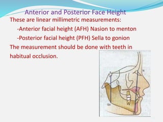
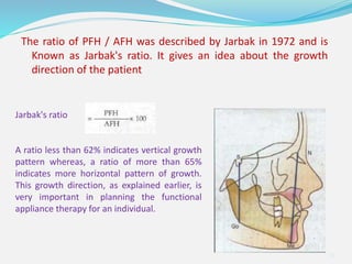
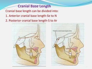
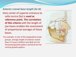
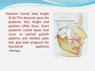
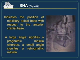
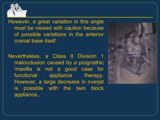
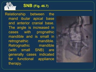
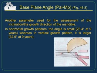
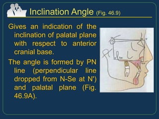
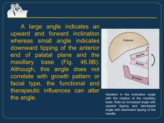
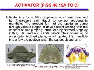
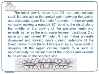
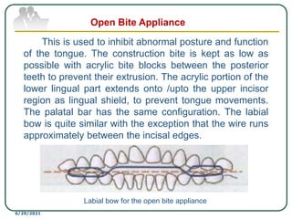
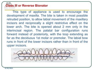
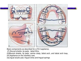
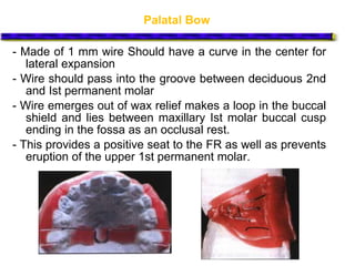
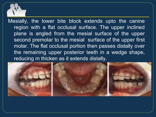
SlideShare a Scribd company logo
LOGO
Functional Appliances
 By; Ammar A. Dae’r
Supervisor; Prof. Maher A. Fouda
• Introduction
• Basis for functional appliances
• Classification of functional appliances
• Cephalometric analysis
• Activator
• Bionator
• Frankel appliance (functional regulator)
• Twin-block
• Fixed functional appliances
• Conclusion
Functional appliances
3
Conventional orthodontic appliances use mechanical
force to alter the position of tooth/ teeth into a more
favorable position. However, the scope of these fixed
appliances is greatly limited by certain morphological
conditions which are caused due to aberrations in the
developmental process or the neuromuscular capsule
surrounding the orofacial skeleton. To over come this
limitation, functional appliances came into being.
INTRODUCTION
 These appliances are considered to be primarily
orthopedic tools to influence the facial skeleton of
the growing child. The uniqueness of these
appliances lies in the fact that instead of applying
active forces, they transmit, eliminate and guide the
natural forces (e.g. muscle activity, growth, tooth
eruption) to eliminate the morphological aberrations
and try to create conditions for the harmonious
development of the stomatognathic system
4
Most of the functional appliances are intraoral
devices, and nearly all of them are tooth
borne or supported by teeth. With a few
exceptions, these appliances are removable,
consisting primarily of acrylic with wire
components for retention and support.
5
Most of the functional appliances are used to
correct early Class II malocclusions and some
cases of Class III malocclusion. About 40
percent of all malocclusions treated belong to
the Class IT category.
6
This preponderance of the Class II
malocclusions seen in orthodontic practice is
partly a result of public awareness of aberrant
characteristics associated with the
malocclusion and education of the public by
the concerned dental practitioners.
7
Too often, Class II malocclusions have been treated
with extra-oral forces directed against the maxilla.
However, abundant research has shown that much of
the problem lies in the mandible, which is
retrognathic (small) or retro-positioned (backwardly
placed) or a combination of both. Nevertheless the
past 30 years have seen an increasing awareness
regarding the potential of functional appliances as a
valuable tool in the armamentarium of an
orthodontist.
8
9
Although functional appliances have been
in use for over two centuries, their scope
and potential has been realized only
recently with the recognition of
interrelationship between form and
function and the realization that neuro-
muscular involvement is vital in
treatment.
Graber described the 'Three Ms: Muscles,
Malformation and Malocclusion in 1963.
Melvin Moss, again validated the concept of
form and function through his theory 'The
Functional Matrix Hypothesis'.
Another factor that gave impetus to the use of functional
appliances (especially mandibular hyperpropulsers) was
the identification of certain cartilages in the body as
'Secondary cartilages‘ .
Secondary cartilage is that' cartilage which is not of
developmental origin but rather differentiates from the
bony periosteum in response to the needs of the body,
e.g. condylar cartilage.
Among the other features of the secondary
cartilages (Table 46.1) the characteristics which
make it useful for functional appliance therapy
is its adaptive growth response to the local
intrinsic and extrinsic stimuli, unlike the
primary cartilages which are minimally
responsive to local factors/stimuli.
Other factors / theories have also been proposed in
favor of the use of Functional appliances which include -
hyperactivity of the lateral pterygoid and the Cybernetic
growth theory (proposed by Petrovic and associates) and
more recently the 'Growth Relativity Theory' (Vodouris &
associates) which was proposed after extensive research and
shows that significant remodeling in the glenoid fossa and
the mandibular condyle takes place in response to the mand
ibular hyperpropuJsers.
However, one question that still looms large is
whether the functional appliance therapy
actually causes growth modification (beyond
genetic potential) or just growth re-direction.
Although answers to these questions are
still at large, one thing is clear that growth
modification and growth re-direction both take
place to varying degrees depending on various
factors like the age of the patient, diagnosis
and skill of the clinician, etc.
18
Myofunctional appliances
are classified as:
I. Classification put forth by Tom Graber when
functional appliances were removable:
1. Group A- Teeth supported appliances, e.g.
catlans appliance, inclined planes, etc.
2. Group B- Teeth/tissue supported, e.g. activator,
bionator, etc.
3. Group C- Vestibular positioned appliances with
isolated support from tooth/tissue, e.g. Frankel
appliance, lip bumpers.
1. Removable functionals, e.g. activator, bionator,
frankel, etc.
2. Semi-fixed functional appliances, e.g. Den Holtz,
Bass appliances, etc.
3. Fixed functional appliances, e.g. Herbst, Jasper
jumper, Churro jumper, Salf springs, adjustable
corrector, Eureka spring, mandibular anterior
repositioning appliance, (MARA), Klapper super
spring, Sabbagh universal spring (SUS).
II. With advent of fixed functional appliances, a
new classification evolved:
III. With concept of hybridization by Peter Vig,
functionals were classified as:
1. Classical functional appliances, e.g. activator,
Frankels appliance, etc.
2. Hybrid appliances, e.g. propulsor, double oral
screen, hybrid bionators, Bass appliance.
IV. Classification put forth by Profitt
1. Teeth borne passive appliances-myotonic appliances,
e.g. Andresen/Haupl activator, Herren activator,
Woodside, activator, Balter's bionator etc.
2. Tooth borne active applianccs-c-myodynamic
appliances, e.g. elastic open activator (EOA), Birnler's
appliance, modified bionator, stockfish appliance, etc.
3. Tissue borne passive appliance, e.g. oral screen, lip
bumpers, etc.
4. Tissue borne active appliances, e.g. Frankel appliances.
5. Functional orthopedic magnetic appliances (FOMA)
24
Cephalometric analysis attempts to define
normal/ abnormal craniofacial pattern by
examining the angular and linear
relationships of clearly defined skeletal
landmarks.
However, as far as patients for
functional appliance therapy are concerned,
this seemingly simple approach is
complicated by the unpredictability in the
nature, dimension, rate and direction of
growth. Therefore, cephalometric diagnostic
assessment for functional appliance patient
include 4 areas of emphasis:
1. Increment of growth direction vector
2. Assessment of magnitude of growth
change
3. Assessment of constantly changing
inclination of upper and lower incisors
4. Radiographic cephalometries.
The various cephalometric analysis for
functional appliance therapy for
patients can be divided into 3 groups
1. Facial skeleton
2. Jaw bases
3. Dentoalveolar relationships
29
This includes three angular measurements
1. Saddle angle
2. Articular angle
3. Gonial angle
and four linear measurements
- Anterior and posterior facial height
- Anterior and posterior cranial base length
30
Formed by joining these 3
points. A large saddle
angle signifies posterior
condylar position and a
mandible which is
posteriorly placed with
respect to cranial base
and maxilla..
31
Saddle Angle (N-S-Ar)
However, it has been
seen that the posterior
positioning of the fossa is
sometimes compensated
by the articular angle and
the ramal length.
Nevertheless, a non-
compensated posterior
positioning of mandible
caused by a large saddle
angle is difficult to
influence with functional
therapy
32
It is the constructed angle
between Sella, Articulare
and Gonion. It is large if
mandible is retrognathic
and small if mandible is
prognathic. Can be
influenced by orthodontic
and orthopedic therapy.
33
Articular Angle (S-Ar-Go)
A decrease in the articular angle
can be seen in the following
conditions:
• Anterior positioning of the
mandible
• Closing of the bite
• Mesial migration of posterior
segment.
34
An increase in the articular angle is
seen in:
• Posterior relocation of mandible
• Opening of the bite
• Distal driving of posterior teeth
An angle formed by tangents to the
body of the mandible and
posterior body of the ramus.
 Acute or small angle, signifies
the' horizontal growth direction,
a condition favorable for
functional appliance
therapy/anterior positioning of
mandible. Large gonial angle
signifies vertical growth
direction.
35
Gonial Angle (Ar-Go-Me)
 Functional appliance
treatment in such cases is
generally contraindicated,
and if attempted should be
directed towards reducing
the vertical facial growth of
the patient.
36
These are linear millimetric measurements:
-Anterior facial height (AFH) Nasion to menton
-Posterior facial height (PFH) Sella to gonion
The measurement should be done with teeth in
habitual occlusion.
37
Anterior and Posterior Face Height
The ratio of PFH / AFH was described by Jarbak in 1972 and is
Known as Jarbak's ratio. It gives an idea about the growth
direction of the patient
38
Jarbak's ratio
A ratio less than 62% indicates vertical growth
pattern whereas, a ratio of more than 65%
indicates more horizontal pattern of growth.
This growth direction, as explained earlier, is
very important in planning the functional
appliance therapy for an individual.
Cranial base length can be divided into:
1. Anterior cranial base length-Se to N
2. Posterior cranial base length-S to Ar
39
Cranial Base Length
Anterior cranial base length (Se-N)
Here center of superior entrance to
sella turcica (Se) is used as
reference point. The correlation
of this criteria with the length of
jaw bases enables the assessment
of proportional averages of these
bases.
For example, in one of the longitudinal study
groups, average length of anterior cranial
base in 9 years-children was 68.8 mm for
horizontal growth pattern and 63.8 mm for
vertical growth pattern.
40
Posterior cranial base length
(S-Ar) This depends upon the
posterior face height and
position cifthe fossa. Short
posterior cranial bases that
occur in vertical growth
patterns and skeletal open
bite, give poor prognosis for
functional appliance
.therapy.
41
It is done to assess the sagittal and vertical
relationships of jaw bones to each other
as well as to the cranium. appliance.
ANALYSIS OF JAW BONES
Indicates the position of
maxillary apical base with
respect to the anterior
cranial base.
A large angle signifies a
prognathic maxilla
whereas, a small angle
signifies a retrognathic
maxilla.
SNA (Fig. 46.6)
However, a great variation in this angle
must be viewed with caution because
of possible variations in the anterior
cranial base itself.
Nevertheless, a Class II Division 1
malocclusion caused by a prognathic
'maxilla is not a good case for
functional appliance therapy.
However, a large decrease in overjet
is possible with the twin block
appliance..
Relationship between the
mand ibular apical base
and anterior cranial base.
The angle is increased in
cases with prognathic
mandible and is small in
retrognathic mandible.
Retrognathic mandible
(with small SNB) are
generally cases indicated
for functional appliance
therapy.
SNB (Fig. 46.7)
Another parameter used for the assessment of the
inclination/the growth direction of the mandible.
In horizontal growth patterns, the angle is small (23.4° at 9
years) whereas in vertical growth pattern, it is larger
(32.9° at 9 years).
Base Plane Angle (Pal-Mp) (Fig. 46.8)
Gives an indication of the
inclination of palatal plane
with respect to anterior
cranial base.
The angle is formed by PN
line (perpendicular line
dropped from N-Se at N')
and palatal plane (Fig.
46.9A).
Inclination Angle (Fig. 46.9)
A large angle indicates an
upward and forward inclination
whereas small angle indicates
downward tipping of the anterior
end of palatal plane and the
maxillary base (Fig. 46.9B).
Although, this angle does not
correlate with growth pattern or
facial type, the functional and
therapeutic influences can alter
the angle.
Variation in the inclination angle
with the rotation of the maxillary
base. Note an increased angle with
upward tipping and decreased
angle with downward tipping of the
maxilla
The craniofacial skeleton is a dynamic entity
wherein no cephalometric landmark can be taken as
a standard. Hence, a composite view of all the
previously described cephalometric measurements
should be taken into consideration before arriving at
any conclusion. This is particularly true in cases with
rotation of the jaw bases or the cranial base towards
or away from each other, which leads to a great
variation in the cephalometric angular
measurements that mayor may not corelate well
with the clinical findings.
Rotation of Jaw Bases (Figs 46.10A to D)
Rotation of the jaw bases. (A) Convergent rotation of the jaw
bases. (B) Divergent rotation of the jaw bases. (C) Cranial rotation
of the jaw bases. (D) Caudal rotation of the jaw bases
EVALUATION OF THE
LENGTH OF JAW BASES
Not only the position, but also the length of jaw bases is an
important consideration in the etiology and therapy of
functional appliance cases. Hence, the length of maxillary
and mandibular bases and the ascending ramus is
measured relative to Se-N The ideal dimensions as
proposed by Schwarz (1958) are:
1. Se-N: Mandibular base 20:21
2. Ascending ramus: Mandibular base 5:7
3. Maxillary base: Mandibular base 2:3
It is the distance Go-Pog projected perpendicularly on to
the mandibular plane.
The growth changes of the mandibular base in relation to
anterior cranial base (Se-N) have been shown in the
Table 46.2:
Mandibular Base (Fig. 46.11)
Table 46.2: Growthchanges in the mandibularbase in relationto the anteriorcranial base
Correlation between the length and position of the
mandible should also be examined. A
retrognathic mandible may either have a long
base or short base. If base is short, cause of
retrognathism is possibly a growth deficiency. If
a favorable growth direction is present,
prognosis for functional appliance therapy is
good.
A mandibular base that is long and retrognathic can result
from mandible that is functionally retruded because of
overclosure and occlusal guidance. Treatment consists
of elimination of forced guidance.
Mandible which is morphogenetically built into the facial
skeleton in a posterior position, shows poor prognosis
for functional therapy.
Length of maxillary base is measured between PNS and
point A projected perpendicularly onto the palatal plane.
Maxillary Base (Fig. 46.11)
Assessment of the length of the maxillary base has two
ideal values-one related to the distance N-Se, the other
to the length of the mandibular base. A deviation from
the mandibular base-related norm indicates that the
maxillary base is too long or too short. If the maxillary
base corresponds to the mandibular base-related norms,
the facial skeleton is proportionally developed.
Length of ascending ramus is
measured between gonion and
condylion.
This length is important in determining
the posterior facial height and
consequently the growth pattern of
an individual.
Evaluation of ramal length should also
be done in relation to other
proportions so as to be able to
predict the possible growth
increments and consequently the
efficacy of the functional therapy.
Ascending Ramus (Fig. 46.12)
Morphology of the mandible varies according to
different facial types. The various facial types
seen are:
• Orthognathic
• Retrognathic
• Prognathic
Morphology of the Mandible
In orthognathic type- Ramus and body of mandible are fully
developed, width of ascending ramus is equal to height
of the body of mandible, including height of the alveolar
process and incisors.
 Condylar and coronoid process are almost on the same
plane. Symphysis is well developed.
In the retrognathic type- Corpus is narrow
particularly in the molar region, symphysis is
narrow and long. Ramus is short and narrow.
Coronoid process is shorter than condylar
process. Gonial angle is obtuse or large.
In prognathic type- Corpus is well developed and
wide in molar region. Symphysis is wider in the
sagittal plane. Ramus is wide and long. Gonial
angle is acute or small.
 The prognathic mandible grows horizontally. Even if an
average or slightly vertical growth direction is evident in
mixed detention, it shifts to horizontal pattern in following
years.
 In retrognathic mandible, shifting of the growth pattern in
opposite direction is unlikely.
ANALYSIS OF DENTOALVEOLAR
RELATIONSHIPS
An assessment of constantly changing inclination and
position of incisors with respect to anterior cranial base,
their apical bases, and each other is an important factor
in deciding the type and construction of functional
appliance for a patient.
Upper incisor: The posterior angle between the long axis of
upper incisor and SN line is measured (Fig. 46.14A).
The measurement averages 94°-100° until the age of 7
years. However, the angle increases slightly to an
average of 102° after the eruption of permanent teeth.
A large angle indicates proc1ined incisors, a smaller angle
indicates incisor retrusion
Axial Inclination of the Incisors (Fig 46.14)
Axial inclination of the upper and lower incisors
Lower incisor: Posterior angle between the long axis of
lower incisor and mandibular plane.
Average measurement is 90°-95°. Larger angle indicates
labially tipped incisors which makes the functional
appliance therapy difficult. Smaller angle indicates
retroclined incisors which is
advantageous for functional
appliance therapy.
Axial inclination of the upper and lower incisors
Position of incisors This is the linear measurement and is
done between the incisal edges of the incisors to N-Pog
line. ldeal position of maxillary incisors is 2-4 mm
anterior to N-Pog line (Fig. 46.14B)and lower incisors 2
mm anterior/posterior to N-Pog line (Fig. 46.14C).
However, the reliability of these measurements in
growing individuals is questionable because of the
constantly changing reference points, i.e. nasion and
pogonion, themselves.
VISUALTREATMENT OBJECTIVE (VTO)
One of the important criteria in case selection for the
functional appliance therapy is eliciting a positive VTO.
VTO is said to be positive if, the profile of the patient
improves noticeably when the patient advances the
mandible voluntarily to correct the overjet. A negative
VTO, i.e. patient whose profile does not improve/
worsens on voluntary forward posturing of the mandible,
are not good candidates for the functional appliance
therapy.
ACTIVATOR (FIGS 46.15A TO C)
Activator is a loose fitting appliance which was designed
by Andreasen and Haupl to correct retrognathic
mandible. The present form of the appliance came
through various stages of development starting with the
concept of 'bite jumping' introduced by Norman Kingsley
(1879). He used a vulcanite palatal plate consisting of
an anterior inclined plane, which guided the mandible
into a forward position when the patient closed on it.
The activator (frontal view)
The activator (superior view)
The activator(lingualview) showingthe
jack screw (Photograph courtesy:
Dentaurum Germany
This was followed by Hotz's Vorbissplatte
whim was a modification of Kingsley's
plate and was used to correct retrognathic
mandible with deep bite.
The activator (frontal view)
The activator (superior view)
The activator(lingualview) showingthe
jack screw (Photograph courtesy:
Dentaurum Germany
Monobloc which was made up of a single block of vulcanite,
was used by Pierre Robin to correct the airway
obstruction in patients with micrognathia
.
Later in 19013 Viggo Andreasen, modified the Hawley's
type of retainer, on the maxillary arch, to which he added
a lower lingual horse shoe shaped flange which helped to
position the mandible forward. He called it the
biomechanical working retainer. Later he teamed with
Karl Haupl, and developed an appliance which they
called as Norwegian appliance and later came to be
known as the activator.
INDICATIONS
Actively growing individual with favorable growth pattern
are good candidates for the activator therapy.
Various types of activators have been devised for the
treatment of various conditions like:
• Class II division 1 malocclusion
• Class II division 2 malocclusion
• Class Ill malocclusion
• Class I open bite malocclusion
• Class I deep bite malocclusion
• For post-treatment retension
• Children with decreased facial height
CONTRAINDICATIONS
• Cannot be used in correction of Class I
problems of crowded teeth where there is
disharmony between tooth size and jaw size
• Cannot be used in children with excess lower
facial height
• Cannot be given in cases with lower
proclination
• In case of nasal stenosis
• In non-growing individuals
ADVANTAGES
 Uses existing growth
 Minimal oral hygiene problems
 Appointments usually short
DISADVANTAGES
 Requires good patient co-operation
 Cannot produce precise detailing and
finishing of occlusion.
PHILOSOPHY OF ACTIVATOR
Various views have been put forward to explain the mode of action of the
activator. Some implicate the reflex myotactic .activity and isometric
contractions while others attribute the results to the viscoelastic
properties and stretching of the muscles and soft tissues.
However the basic fact remains that most of the changes are induced by
holding the mandible forward and the ensuing reaction of the stretched
muscles and soft tissues, transmitted to the periosteum, bones and the
teeth.
A restraining effect on the growth of the maxilla and the maxillary
dentoalveolar complex is also seen along with the stimulation of
mandibular growth and mandibular alveolar adaptation.
Research has also shown favorable changes in the TMJ region.
COMPONENTS OF THE ACTIVATOR
it consists of the following elements .
1. Labial bow The wire used is spring hardened 0.9 mm
stainless steel. The primary wire element of the activator
consists of an upper and/or lower labial bow. It consist of
horizontal middle sections, two vertical loops and wire
extensions through the canine-deciduous first molar
embrasure into the acrylic body.
2. Jack screw Optional (fitted to maxillary arch).
3. Acrylic portion This can be fabricated in cold cure acrylic
directly on the models or a wax matrix can be made first
and then invested in the flask.
CONSTRUCTION BITE
It is an intermaxillary wax record used to relate the mandible to the
maxilla. This is done to improve the skeletal inter-jaw
relationship. In most cases bite opening is by 2-3 mm and
advancement is by 4-5 mm.
General considerations for construction bite
1. In case the overjet is too large, forward positioning is done in 2-3
stages
2. In case of forward positioning of the mandible by 7-8 mm, the
vertical opening should be slight to moderate i.e. 2-4 mm.
3. If the forward positioning is not more than 3-5 mm then the
vertical opening can be 4-6 mm
Lower construction bite with marked
mandibular forward positioning
This kind of construction bite is characterized by marked
forward positioning of the mandible with minimum
vertical opening. As a rule of the thumb the anterior
advancement should not exceed more than 70% of the
most protrusive position, and vertically it should be
within the limits of inter occlusal clearance.
This kind of an activator with marked sagittal advancement with
minimal bite opening is called H-activator and is indicated in
persons with Class II Division 1 malocclusion with horiozontal
growth pattern.
CONSTRUCTION BITE
High construction bite with slight anterior
mandibular positioning
Here mandible is positioned anterioriy by 3-5mm only
and the bite is opened vertically by 4-6 mm. This kind
of activator constructed with minimal sagittal
advancement but marked vertical opening is called a
'V' activator and is indicated in Class II Division 1
malocclusion with vertical growth pattern.
CONSTRUCTION BITE
Construction bite without forward positioning
of mandible
It is done in cases with deep bite, and open
bite.
CONSTRUCTION BITE
Construction bite with opening and posterior
positioning of the mandible
In Class III cases bite is taken after retruding
the mandible to a more posterior position.
In this a vertical opening of 5 mm and a
posterior positioning of 2 mm is required.
CONSTRUCTION BITE
FABRICATION
Impressions of upper
and lower arches are
made to construct 2
pairs of models - study
models, working models
Impressions
Bite
Registration
• Amount of sagittal and vertical
advancement is planned
• Horse-shoe shaped wax block is
prepared. Ltshould be 2-3 mm more than
the vertical opening planned
• Patient is asked to practice placement of
mandible at the desired position
• Horse-shoe shaped wax block is placed
on the occlusal surface of one of the cast,
maxillary or mandibular (maxillary
preferred) and is pressed gently to form
indentation of the teeth on the wax.
• It is then removed and
placed in the patients mouth
and the patient is asked to
bite in the proposed sagittal
position
• If found all right it is chilled
and once again tried on the
cast and then checked again
in the patients mouth.
Bite
Registration
Upper and lower casts are
articulated with the
construction bite in place.
The upper and lower casts
are articulated in a reverse
direction facing the hinge.
This is to get easy access to
the palatal surface of the
upper and Ungual surface of
the lower casts.
Articulation of
the Model
A labial bow is prepared
with 0.8 or 0.9 mm wire.
The ends of the wire
enter the acrylic body.
The labial bow can be
active or passive.
Preparation
of Wire
Elements
Fabrication of Acrylic Portions
Appliance consists of three parts (Figs 46.15A and B)
• Maxillary part
• Mandibular part
• lnterocclusal part
The maxillary and mandibular parts are same as the acrylic
portions of upper and lower Hawley's plate, but these are
joined by an interocclusaJ part which makes this appliance
into a single block. The inter occlusal portion has the
indentations of upper and lower teeth and caps the lower
anteriors, which controls their supra-eruption and
proclination.
Trimming of the Activator
Activator therapy aims at providing a good skeletal as well
as dentoalveolar relationship of upper and lower arches.
However, this is not possible by simply holding/posturing
the mandible forward, in a predetermined position,
without appropriate guidance for the erupting teeth.
Therefore, to achieve a proper three dimensional
relationship of teeth, selective trimming of the activator
is carried out. Trimming can be done at the time of
appliance insertion or as some clinicians suggest, it can be
done after about a week's time.
89
Trimming for Sagittal Control
a. Class II correction: Trimming is done so as to encourage
the mesial movement of the lower molar and distal
movement of the upper molar. Therefore, the distopalatal
surface in the maxillary and mesio lingual surface in the
mandibular posterior segments are trimmed. This pattern
of trimming is particularly useful in horizontally growing
patients as it tends to open the bite due to molar
eruption.
Trimming of the activator for Class II correction. Note the lower posterior segment is free to erupt vertically
and mesially. thus helping in the correction of deep overbite and Class 11 relation
b. Protrusion of incisors
• In this case lingual surfaces of teeth are loaded with
acrylic and a passive labial bow is given (Fig. 46.15E i).
c. Retrusion of incisors
• Here the lingual surface is made totally free of acrylic and
an active labial bow is given (Fig. 46.15E ii).
91
Activator design for
protrusion of
incisors.
Note the loading of
the entire lingual
surface and labial
bow away from the
incisors to
encourage labial
movement of the
incisors
Activator design
for retrusion of
incisors. The labial
bow here is active
and the lingual
surfaces of the
incisors are
relieved for lingual
movement of the
teeth
Trimming for Vertical Control
 a. lntrusion of teeth (Fig. 46.15F)
• For this the incisal area is loaded with acrylic
• Labial bow is placed below the greatest convexity at the incisal
area for intrusion
• In case of intrusion of posteriors load the surfaces of the teeth
with acrylic.
92
Activator design for
intrusion of teeth (for
anterior intrusion the
labial bow is placed
below the greatest
convexity in the upper and
above the greatest
convexity in the lower)
 b. Extrusion of teeth (Figs 46.15Gi and ii)
• Here the lingual surface is loaded above the area of greatest
convexity in the maxilla and below the area of greatest
convexity in the mandible
• Also the labial bow can be placed at the gingival 1/3 i.e. below
the greatest convexity
• In case of posterior extrusion the lingual surfaces below the
greatest convexity are loaded.
93
Trimming for Vertical Control
Activator design for extrusion of
teeth.
(i)Anteriors.(ii)Posteriors
For Transverse Control (Fig. 46.15H)
Jack screw is incorporated into the activator for
expansion (transverse control) as and when
required.
94
Activator with jack screw, for
transverse control
MANAGEMENT OF THE APPLIANCE
The patient is demonstrated to place and remove the
appliance in mouth. The appliance is to be worn 2 to
3 hours during the day for the first week. During the
second week the patient sleeps with the appliance in
mouth and wears it for 1-3 hours each day.
The appliance is checked during the third week to
evaluate the trimming.
If the patient is wearing the appliance without any
difficulty and following the instructions, checkup
appointments are scheduled every 6 weeks
BIONATOR
INTRODUCTION
The bulkiness of the activator and its limitation to night-time
wear was a major deterrent in its greater use by clinicians to
obtain maximum potential of functional growth guidance.
The appliance was too bulky for day-time wear. Moreover,
during sleep, the function is minimized or virtually
nonexistent.
BIONATOR
The bionator
The activitor
 This led to the development of the BIONATOR, a less bulky
appliance. Its lower portion is narrow, and its upper
component has only lateral extensions, with a crosspalatal
stabilizing bar. The palate is free for proprioceptive contact
with the tongue and the buccinator wire loops hold away the
potentially deforming muscles.
 The appliance developed by BALTERS in 1960, can be worn
all the time, except during meals.
INTRODUCTION
BIONATOR
The bionator (standard appliance) Bionator (lateral view). Note that the palatal acrylic coverage has
been replaced by the palatal bow and the buccal extensions of
the labial bow which keep the deforming cheek muscles away
According to Balters, "the equilibrium between the
tongue and the circumoral muscles is responsible for the
shape of the dental arches and that the functional space for
the tongue is essential for the normal development of the
orofacial system" e.g. posterior displacement of the tongue
could cause Class II malocclusion.
6/29/2021
PHILOSOPHY OF BIONATOR
Taking into consideration the dominant role of the
tongue, Balters designed an appliance, which could take
advantage of tongue posture. Thus he constructed an
appliance whereby the mandible was positioned
anteriorly, with the incisors in an edge to edge position.
This forward positioning brought the dorsum of the tongue
in contact with the soft palate and helped accomplish lip
closure.
6/29/2021
Thus the principle of bionator is not to activate the
muscles but to modulate muscle activity, thereby
enhancing the normal development of the
inherent growth pattern and eliminate abnormal
and potentially deforming environmental factors.
6/29/2021
Three basic constructions are common in
bionator
• Standard appliance
• Open-bite appliance
• Class III or reverse bionator
6/29/2021
BIONATOR TYPES
It consists of a lower horse-shoe shaped acrylic lingual
plate extending from the distal of the last erupted molar
to the corresponding point on the other side.
For the upper arch the appliance has only posterior lingual
extensions that cover the molar and premolar regions.
The anterior portion is open from canine to canine. The
upper and lower parts, which are joined interocclusally,
extend 2 mm above the upper gingival margin and 2 mm
below the lower gingival margin.
6/29/2021
Standard Appliance;-
The palatal bar is formed of 1.2 mm hard stainless steel
wire extending from the top edges of the lingual acrylic
flanges in the middle area of the deciduous first molars.
The palatal bar forms an oval, posteriorly directed loop
that orients the tongue and mandible anteriorly to
achieve a Class I relationship.
6/29/2021
The labial bow is made from 0.9 mm hard stainless
steel. It starts above the contact point between the canine
and deciduous upper first molar/ premolar. It then extends
vertically, making a rounded 90° bend to the distal along
the middle of the crowns of the posterior teeth and
extends as far as the embrasure between deciduous 2nd
molar and permanent 1st molar. It then makes a gentle
downward and forward curve running anteriorly till the
lower canine. From there, it forms a sharp curve extending
obliquely till the upper canine, bends to a level at
approximately the incisal third of the incisors and extends
to the canine on the opposite side.
6/29/2021
This is used to inhibit abnormal posture and function
of the tongue. The construction bite is kept as low as
possible with acrylic bite blocks between the posterior
teeth to prevent their extrusion. The acrylic portion of the
lower lingual part extends onto /upto the upper incisor
region as lingual shield, to prevent tongue movements.
The palatal bar has the same configuration. The labial
bow is quite similar with the exception that the wire runs
approximately between the incisal edges.
6/29/2021
Open Bite Appliance
Labial bow for the open bite appliance
This type of appliance is used to encourage the
development of maxilla. The bite is taken in most possible
retruded position, to allow labial movement of the maxillary
incisors and reciprocally a slight restrictive effect on the
lower arch. The bite is opened about 2 mm only in the
interincisal region. The palatal bar configuration runs
forward instead of posteriorly, with the loop extending as
far as the deciduous 1st molar or premolar. The labial bow
runs in front of the lower incisors rather than in front of the
upper incisors.
6/29/2021
Class III or Reverse Bionator
INDICATIONS FOR BIONATOR THERAPY
Bionator is indicated for the treatment of Class II Division 1
malocclusion in the mixed dentition using the standard
bionator under the following conditions:
• Well aligned dental arches.
• Functional retrusion
• Mild to moderate skeletal discrepancy
• No evidence of labial tipping seen
6/29/2021
CONTRAINDICATIONS
• Class II relationship caused by maxillary
prognathism
• Vertical growth pattern
• Labially tipped lower incisors.
www.themegallery.com
6/29/2021
ADVANTAGES OF BIONATOR
1. Appliance is less bulky.
2. Can be worn full time, except during meals.
3. Appliance exerts a constant influence on the
tongue and perioral muscles.
DISADVANTAGE OF APPLIANCE
The main disadvantage lies in the difficulty of
correctly managing it.
www.themegallery.com
6/29/2021
THE FRANKEL
FUNCTION
REGULATOR
THE FRANKEL FUNCTION REGULATOR
Function regulator appliances were developed by Rolf
Frankel (Germany). Frankel believed that the active
muscle and tissue mass i.e., the buccinator mechanism
and the orbicularis oris complex have a major role in the
development of skeletal and dentofacial deformities.
Hence he developed function regulators as orthopedic
exercise devices, to aid in the maturation, training and
reprogramming of the orofacial neuromuscular system.
FRANKEL PHILOSOPHY
1.. Vestibular area of operation
- Shields of the appliance extend to the vestibule and
this prevents the abnormal muscle function.
2. Sagittal correction via tooth borne maxillary anchorage
- Appliance is fixed on the upper arch by grooves mesial
to the 1st permanent molar and distal to the canine in
the mixed dentition period.
- Presence of the lingual pad acts as proprioceptive
stimulus and helps in the forward posturing of the
mandible.
FRANKEL PHILOSOPHY
3. Differential eruption guidance
- Frankel is placed on the upper teeth.
- Mandibular posterior teeth are free to erupt and their
unrestricted upward and forward movement contributes to
both vertical as well as horizontal correction of the
malocclusion.
4. Periosteal pull by buccal shields and lip pad
- Presence of buccal shields and lip pads exert the
periosteal pull which helps in bone formation and lateral
expansion of the maxillary apical base.
5. Minimal maxillary basal effect
- Downward and forward growth of maxilla seems to be
restricted, even though lateral maxillary expansion in
seen.
MODE OF ACTION OF FR
1. Increase in transverse sagittal direction
- by use of buccal shields and lip pads
2. Increase in vertical direction
- by allowing the lower molar to erupt freely because
appliance is fixed to the upper arch
3. Muscle adaptation
- The form and extension of the buccal shields and lip
pads along with the prescribed excercises corrects
the abnormal peri-oral muscle activity.
ORAL EXERCISES WITH FRANKEL
- Frankel-full time wear appliance.
- Lips to be closed at all times or keep a paper
between the lips
- Swallowing, speaking, etc. with the appliance
in mouth, itself serves as an exercise
TYPES OF FUNCTION REGULATORS
1. FRl- used for Class I and Class II, Division 1.
FRla -used for Class I, moderate crowding and deep bite.
PRlb -used for Class [J Division 1 overjet less than 7mm.
FRlc-used for Class II Division 1 overjet more than 7mm.
2. FR Il -used for Class II Division 2 and Division 1 (Figs
46.17A and B)
3. FR Ill -used for Class UI (Figs 46.17C to E)
4. FR IV -used for cases with open bite and
bimaxillary protrusion.
5. FR V- FR with headgear.
FR Il -used for Class II Division 2 and
Division 1
Frankel11 (superior view showing
parts of the appliance
Frankel II (frontal view showing
parts of the appliance)
FR Ill -used for Class III
Frankel III (for Class III cases Frankel lll in mouth
Patient with Frankel lll
FABRICATION OF FUNCTION REGULATOR
PARTS OF THE APPLIANCE (FIGS 46.17A,B
AND F TO I)
Acrylic part
Buccal shields
Lip pads
Lower lingual pads
Wire parts
Palatal bow
Labial bow
Canine extensions
Upper lingual wire (only in FR Il)
Lingual cross over wire
Lip pads
Lower lingual springs
Basic components as described for a FA II appliance.
(F) Buccal shields ,lip pads, labial Wire,
(G)Buccal shields, lip pads, canine clasp, labial arch, and labial arch loop,
(H) Appliance on the maxillary cast,
(I)Lingual acrylic pad, lingual wires and lingual springs
IMPRESSIONS
The impressions should reproduce the whole
alveolar process to the depths of the sulci, including the
maxillary tuberosities. The soft tissues and the muscle
attachments should not be distorted. A custom tray can
also be fabricated based on the study models, if
desired. Since the appliance is anchored in the
maxillary arch between the deciduous second molar
and the permanent first molar, separators should be
placed between these teeth prior to impressions;
otherwise, disking of the distal surface of the primary
second molar, can also be done after fabrication of
appliance.
WORKING MODEL POURING AND TRIMMING
- Model base must extend away from alveolar
process by at least 5 mm
- Correct model trimming is necessary
before appliance fabrication
- The desired amount of stone to be cut is
outlined with a pencil before trimming.
- Then it should be cut with a round bur
- Final detailing is done with plaster knife.
- No trimming required for buccal shields on
mandible.
- But trimming is required in the maxillary
buccal shield area and lower lip pad area.
- Care must be taken not to disturb the
muscle attachments.
WORKING MODEL POURING AND TRIMMING
TRIMMING FOR LIP PADS
- 5 mm from greatest curvature of alveolar
base to ensure optimum extension.
- Lower relief should be 12 mm below
gingival margin.
TRIMMING FOR LIP PADS CONSTRUCTION BITE
For minor sagittal problems, the construction bite is
taken at and end-to-end incisor relationship, with the
mandible position forward not more than 2.5 to 3 mm. A
clearance of at least 2.5 to 3.5 mm in the buccal segments
is necessary to allow the crossover wires to pass through in
the Frankel appliance.
Dental midline discrepancies should not be corrected in the
bite by manipulation during forward posturing. The
construction bite should be checked on the casts and the
cases should be mounted with the bite.
Constructionbite for FR 11.Note that the
dental midline deviation should not be
corrected in the construction bite
unless the skeletal midlinesare
deviatingas well
WAX RELIEF (FIGS 46.17K TO M)
Relief is placed such that the buccal shields
and lip pads stay away from teeth and tissues to
achieve the desired expansion. Thickness of wax
depends on the expansion required but should
not exceed 4-5 mm in the tooth area and 2.5-3
mm in the alveolar area in the maxilla.
Wax relief in the maxillary arch. Note the
Configuration of the palatal bow as well
In the mandible, only 0.5 mm of relief is
given (Fig. 46.17L). Thickness of relief wax is
greater in maxilla because of arch narrowing in
case of Class II Division 1 malocclusions
Wax relief on the mandibular cast
Complete wax up of the Frankel. Ready for
the fabrication of the buccal shields in cold
cure acrylic
WIRE COMPONENTS (FR Ib)
Consists of:
• Stabilizing wires
• Tooth moving wires
Lower Lingual Support Wire
 - Made of 1.25 mm wire
 - Can be one unit or 3 separate parts
 - Horizontal reinforcing wire element contours to the
lingual apical base 1-2 mm away from the mucosa and
3-4 mm below the gingival margin so as to permit adding
acrylic to the pad.
 - Cross over wire pass between deciduous first and 2nd
molar
 - Ends are then bent at 90° to insert into the buccal
shields. The ends must be parallel to each other and the
occlusal plane to allow for advancement of the anterior
section later if needed.
Lower Lingual Springs
 - Made of 0.8 mm wire.
 - Right above the cingula the wire is curved about 3
mm below the incisal margin
 - Function-is to prevent extrusion of lower incision
 - Should not be active only passive
 - If tooth movement is required the spring is made
active.
Lower Labial Wires
- Made of.9 mm wire
- Acts as a skeleton for lower lip pads
- It can be one piece or three piece
- It should be 1 mm away from the tissue.
- Wire frame-work should be 7 mm below the
gingival margin
- Middle part should be inverted 'V' shaped for
labial frenum relief.
Palatal Bow
- Made of 1 mm wire Should have a curve in the center for
lateral expansion
- Wire should pass into the groove between deciduous 2nd
and Ist permanent molar
- Wire emerges out of wax relief makes a loop in the buccal
shield and lies between maxillary Ist molar buccal cusp
ending in the fossa as an occlusal rest.
- This provides a positive seat to the FR as well as prevents
eruption of the upper 1st permanent molar.
Labial Bow
Made of 0.9 mm wire
- Originates in buccal shield curves upwards and lies in the
depression between canine and lateral. It is in the
middle of labial surface of incisors and leaves the acrylic
with slight bend towards the sulcus.
- Should be 2 mm away from mucosa Permits canine
eruption and expansion without contacting the labial wire
- Loops should be wide enough to allow activation later to
close anterior space if required.
Canine Loops (For FR la)
-Made of 0.9 mm.
- Embedded in buccal shield at occlusal plane level.
- Turned sharply towards gingival margin of upper
deciduous 1st molar and fit in embrasure between
deciduous first molar and canines.
- Wire wraps around the lingual surface of the canine
emerges labially at the canine-lateral embrasure
curves distally over the canine cusps. Free ends can
be bent occlusally if required.
Canine Loops (For FR II)
- Made of 0.8 mm wire.
- Originate in buccal shield
- Contact canines on buccal surface as recurved
loop.
- Serves as extension of buccal shield in the
canine area whim is normally narrowed by the
peri-oral muscles.
- Should be 2-3 mm away from canines to prevent
restrictive muscle function,
Upper Lingual Wire (Protrusion Bow)
-Made of 0.8 mm wire
-Mostly seen in FR lI and FR III.
-Lingual bow behind the maxillary incisors serves to
maintain pro-functional appliance alignment achieved
and also stabilizes the FR by locking it on to the maxillary
arch
-0.8 wire is used if the centrals are retroclined, but if the
anterior alignment is a!read y achieved a stiffer wire can
be used i.e. 0.9 mm wire.
-It originates in the vestibular shield and passes to the
lingual through the canine-deciduous 1st molar
embrasure.
-Wire forms loops at the palatal mucosa and curve vertically
to contact the incisor at the embrasure between canine
and lateral incisor.
ACRYLIC PARTS
- After the wires are fabricated and adapted they are secured
in place with sticky wax.
- The lip pad, buccal shields, lower lingual pads are
fabricated in cold cure acrylic.
- Total thickness of the acrylic should not exceed 2.5 mm
- Lip pads look like parallelogram (tear drop shape in
longitudinal cross-section)
- Lip pads should be 5 mm from the gingival margin
- Presence of lip pads eliminates mentalis hyperactivity and
abnormal functional lip trap, thereby helps correcting the
overjet.
- Buccal shields should extend past the canine deciduous
first molar embrasure to the middle of the canine.
COMPONENTS OF VARIOUS FR APPLIANCES
FRla
 -Not popular. Replaced by FRIb
- Used for Class I moderate crowding and deep
bite
- Lingual wire loops are given instead of acrylic
lingual pads to posture the mandible forwards
- The cross over wire (passing between upper
and lower occlusal surface) is an extension of
the lingual loops.
FRlc
- used in Class II Division 1 with over jet greater than 7 mm
- It has been observed that posturing the mandible forward into a
Class I relationship and eliminating excessive overjet in one step
for a Frankel appliance is neither feasible nor necessary. Because
tissue response is less favorable and there is increased patient
discomfort or compliance.
- So mandibular protraction is done in 2 or 3 steps.
- Horizontal and vertical cuts are made on the buccal shield and then
made to slide along the hanger .
-The cuts are then filled with cold cure acrylic.
- FRTc is seldom used because FRlb and
FR!1 can be modified in the same way.
Mandibular advancement done in stages. Horizontal and vertical
cuts are made in the acrylic and the lower lingual pad and lip
pads are advanced. The gap is later filled with acrylic
FR II
-Used for Class II Division 2 and Division 1
- Protrusion bow is made unlike in FRI
- Canine loops
• It is only a recurved loop
• It originates in the buccal shield and contacts the buccal
surface of the canine as a recurved loop.
• It shields the canine against the buccinator action.
• It is placed 2-3 mm away from the deciduous canines
FR III
- Used for Class III correction
- Lip pads are in the maxillary arch
- Labial bow resting against mandibular teeth.
Protrusion bow is on the upper teeth and is made of 0.8 mm wire for
forward movement of maxillary incisiors if desired.
- The occlusal rest is on the mandibula rmolar unlike
in FRII where it is on the maxillary molar.
FRIV
- Used for open bite and bimaxillary protrusion
- Has no canine loops
- Has no protrusion bow
- Four occlusal rests present i.e, on deciduous 1st molar
and permanent 1st molar on each side to prevent
eruption of posterior teeth.
- Palatal bar resembles FR III i.e. it does not contact the
teeth
- The buccal shield in FR IV should be wafer thin to enable
lip closure and exercise without which the appliance will
be a failure.
FRV
Frankel appliance used along with head
gear.
TREATMENT TIMING
The best therapeutic effect of the Frankel
appliance is achieved during the late mixed
and transitional dentition period, when both
the soft and hard tissues are undergoing their
greatest transitional changes.
Treatment for Class III and open bite cases
should usually start sooner than for Class II
problems.
TWIN-BLOCK
EVOLUTION OF TWIN-BLOCK
The twin block appliance was developed by
Clark in 1977,and it consists of an upper and
lower device with simple bite blocks that
engage on occlusal inclined planes.
Introduction
The appliance became popular due to a number of
advantages over other functional appliances namely:
1. The functional mechanism is very similar to
that of the natural dentition.
2. The occlusal inclined planes give greater freedom
of movement in lateral and anterior excursion and
cause less interference with normal function.
3. Appearance is noticeably improved.
4. Less bulk, therefore, better patient
compliance.
5. It Can be used in later stages of growth (late mixed ,/
dentition/early permanent dentition)
6. The appliance can be cemented in mouth, without
disrupting the normal oral functions, to improve
patient compliance.
7. Absence of lip pads and buccal shields,
allow patient a much better comfort, however,
modifications containing lip pads can be
incorporated as and when required.
The twin block appliance evolved in response to a clinical
problem that presented when a young patient, the son of
a dental colleague, fell and completely luxated an upper
central incisor. The incisor was reimplanted and a
temporary splint was constructed to hold the tooth in
position.
DEVELOPMENT OF TWIN-BLOCK
After 6 months with a stabilizing splint, the tooth had
partially reattached, but there was evidence of severe
root resorption and the long-term prognosis for the
reimplanted incisor was poor.
The occlusal relationship was Class II Division 1 with an
overjet of 9 mm and lower lip was trapped lingual to the
upper incisors. Adverse lip action on the reimplanted
incisor was causing mobility, and root resorption. To
prevent the lip from trapping in the overjet it was
necessary to design an appliance that could be worn full
time to posture the mandible forward. At that time no
such appliance was available and simple bite blocks
were therefore, designed to achieve this objective.
The appliance mechanism was designed to harness, the
forces of occlusion to correct the distal occlusion and
also reduce the overjet without applying direct pressure
to the upper incisors. The first twin block appliances
were fitted on 7th September 1977.The upper and lower
bite blocks engaged mesial to the 1st permanent molar
at 90° to the occlusal plane, when the mandible
postured forward. This positioned the incisors edge-to-
edge with 2 mm vertical separation to hold the incisors
out of occlusion. The patient had to make a positive
effort to posture the mandible forward to occlude the bite
blocks in protrusive bite.
CASE SELECTION
FOR TWIN-BLOCK
APPLIANCE
Case selection for clinical use of twin-block should,
display the following criteria:
1. Angle's Class IT Division 1malocclusion
with good arch form.
2. A lower arch that is uncrowded or
decrowded and aligned.
3. An upper arch that is aligned or can be
easily aligned.
4. An overjet of 10-12mm and a deep
overbite.
5. A full unit distal occlusion in the buccal
segments.
6. On examination of models in occlusion with the lower
model ad vanced to correct the increased overjet, the
clistal occlusion is also corrected and it can be seen that a
potentially good occlusion of the buccal teeth will result.
7. On clinical examination the profile should be noticeably
improved when the patient advances the mandible
voluntarily to correct the overjet.
8. To achieve a favorable skeletal change, during treatment,
patient should be actively growing. A more rapid growth
response may be observed when the treatment coincides
with the potential growth spurt.
APPLIANCE DESIGN AND
CONSTRUCTION
The present form of the appliance evolved over a period following clinical
experience with the appliance. The earliest design of the twin-block
consisted of:
1. A midline screw to expand the upper arch
2. Occlusal bite block (at 90° to occlusal plane)
3. Clasps on upper molars and premolars (Adams‘ clasp)
4. Clasps on lower premolars and incisors.
5. Springs to move the individual teeth
6. Provision for extra-oraltraclion in some cases. (esp. maxillary
protrusion cases)
EVOLUTION OF THE APPLIANCE
DESIGN
www.themegallery.com
6/29/2021
DELTA CLASPS
After initial use of the Adams' clasp, Clark introduced
the delta clasp in 1985.The basic premise was to
reduce the incidence of breakages (as seen with the
Adams‘ clasp) due to repeated adjustments and
consequent metal fatigue.
LABIAL BOW
The use of labial bow in the upper plate was discontinued
after it was noticed that it causes unwanted retroclination
of upper incisors with consequent deepening of the bite.
This is turn, limited the scope of mandibular correction
possible. However, in certain cases with severe upper
proclination, labial bow in the upper arch may be placed.
BASE PLATE
The design is similar to upper and lower Hawley's plate
and can be prepared in heat cure or cold cure acrylic.
The main advantage of heat cure acrylic is its additional
strength. Cold cure acrylic has the advantage of speed
and convenience, however, strength and accuracy is
slightly compromised.
Position of the bite blocks and the angulation of its inclined
planes are important factors in the success of the twin-
block therapy. The position of the inclined plane is
determined by the lower block and is critical in the
treatment of deep overbite.
OCCLUSAL BITE BLOCKS WITH INCLINED PLANES
(FIG. 46.18F)
Bite blocks with the incline. The lower bite block does not extend beyond half of the primary second molar! 2nd premolar, which
allows free eruption of the lower molar for the correction of Class II occlusion and deep over bite. Also note the angulation of
the inclined planes
The inclined plane on the lower bite-block is angled from
the mesial surface of the second pre-molar or second
deciduous molar at 70° to the occlusal plane. This
places the leading edge of the inclined plane on the
upper appliance mesial to the lower first permanent
molar, thus keeping a provision for the unhindered
eruption of the lower 1st permanent molar.
Mesially, the lower bite block extends upto the canine
region with a flat occlusal surface. The upper inclined
plane is angled from the mesial surface of the upper
second premolar to the mesial surface of the upper first
molar. The flat occlusal portion then passes distally over
the remaining upper posterior teeth in a wedge shape,
reducing m thicken as it extends distally.
The height of the bite blocks is determined by the vertical
opening planned and recorded in the construction bite.
For a twin block therapy, it is recommended that the
vertical opening in the construction bite be beyond the
free way space. This implies that the height of the bite
block should be 4-6 mm so that the mandible does not
go back even in physiologic rest position.
initially, inclined planes were at 90° to occlusal plane. However,
adjustment to this sort of inclined plane was difficult for a lot of
patients.
Therefore, for patient convenience inclined planes were reduced to 45°
but since, this angulation caused equal vertical and horizontal
movement, the angulation was further changed to 70°, so that more
horizontal vector of force would be produced.
Nevertheless, the inclined plane angulation can vary between 45° and
70° depending upon the patient comfort levels.
ANGULATION OF THE INCLINED PLANES
Construction bite for twin-block can be taken
is the conventional manner, by means of
an inter-occlusal wax bite, as described
earlier, for the activator, or by the use of
an 'Exactobite‘.
CONSTRUCTION BITE
BITE REGISTRATION FOR CONSTRUCTION OF TWIN-BLOCKS FOR
CLASS II DIVISION 1 MALOCCLUSION
Exactobite or project-bite gauge is a horse-shoe
shaped device with an anterior handle with various
grooves, designed for accurate control m registering a
protrusive bite for construction of twin block. The blue
bite gauge registers 2 mm vertical clearance between
the incisal edges of the upper and lower incisors, which
are mappropriate interincisal clearance for bite
registration in most Class II Division 1 malocclusionswith
increased overbite.
In a Class 11Division 1 malocclusion a protrusive bite is
registered to red uce the overjet and distal occlusion on
average 5-10 mm on initial activation, depending on the
freedom of movement in protrusive functions. The length
of the patient's protrusive path is determined by
recording the overjet in centric occlusion and fully
protrusive occlusion. The activation should not exceed
70% of the maximum protrusive path.
in growing child, with an overjet of up to 10 mm,
provided the patient can posture comfortably
forwards, bite may be activated up to edge-to-
edge on the incisors with a 2 mm interincisal
clearance. Larger overjet requires partial
correction.
It is best, first to rehearse the procedure of bite registration
with the patient using a mirror. The patient is instructed
to close correctly into the bite gauge before applying the
wax. Once the patient understands, what is required,
softened wax is applied to the bite gauge from a hot
water bath.
The clinician can then place the bite gauge in the
patient's mouth to register the bite. Midlines
should be coincident, however, if dental mid
lines are deviating, skeletal midlines should be
taken into consideration.
One important aspect of the construction bite for the twin-
block appliance is to establish the correct vertical
dimension, The bite should be open slightly beyond the
clearance of the free way space to encourage the pa
tient to close into the appliance rather than allow the
mandible to drop out of contact into rest position.
Hence, an inter-incisal clearance of about 2-3 mm
is established, which is equivalent to an
approximately 5-6mm clearance m the 1st
premolar region and about 3 mm clearance
distally m the molar region.
This amount of vertical clearance ensures that the
mandible does not drop back at rest and that
enough space is available for the vertical
development of the posterior teeth to red uce
the over bite.
ESTABLISHING THE CORRECT VERTICAL DIMENSIONS-
THE INTERGINGIVAL HEIGHT
A simple guide is used to establish the correct vertical
dimension during the twin block phase of treatment.
The intergingival height is measured from the gingival
margin of the upper incisor to the gingival margin of
the lower incisor when the teeth are in occlusion.
The 'comfort zone' for intergingival height for adult
patients is about 17-19 mm. This is equivalent to
combined heights of the upper and lower incisors
minus an overbite within the range of normal.
Patients whose intergingival height varies
significantly from comfort zone are at a greater risk of
developing TMD. This applies both to the patients
with a deep overbite whose intergingival height is
reduced, and to patients with an anterior open bite
who have an increased intergingival height.
The intergingival height is a useful guideline to check
progress and to establish the correct vertical
dimensions during treatment. Measurement of
intergingival height is done by using a mm ruler and
divider or with a Vernier scale to measure the
distance between the upper and lower gingival
margins.
 In twin block treatment the correct intergingival height
is achieved with great consistency. Deep overbite
may be corrected to an intergingival height of 20 mm
to allow for a slight settling in with a resultant overbite
increase after treatment.
 In the younger patient's a range of 15-17 mm is
normal and allowance should be made for the
diminutive height of the clinical crowns.
Patient motivation is an important factor in all removable
appliance therapy. The process of patient education and
motivation continues when the patient attends to have
twin block fitted. It is often helpful to the patient if the
clinician demonstrates twin blocks on models to confirm
that it is a simple appliance system and is easy to wear
with no visible anterior wires.
FITTING TWIN·BLOCKS:
INSTRUCTIONS TO PATIENT
Simply biting the blocks together guides the lower jaw
forward to correct the bite. The appliance system is
easily understood even by young patients, who see that
biting the blocks together corrects the jaw position. It is
important to emphasize positive factors and to motivate
the patient before treatment.
The patient is shown how to insert the twin blocks with the
help of a mirror, pointing out the immediate improvement
in facial appearance when the twin blocks is inserted and
explaining that the appliance will produce this change, in
a few months, provided they are worn full time. A
removable appliance only corrects the teeth when it is in
mouth, and not in the pocket. Both appliances must be
worn full time, especially during eating with sole
exception being removed for cleaning and during
swimming and contact sports.
At first the appliance may feel large in the mouth, but within
a few days, it will be very comfortable and easy to wear.
Twin blocks cause much less interference with speech
than other, one piece functional appliances. For a first
few days, speech will be affected, but will improve and
should return to normal within a week.
As with any new appliances it is normal to expect a little
initial discomfort. But it is important to encourage the
patient to preserve and keep the appliance in mouth at
all times except for hygiene process.
The patient should be advised to remove the appliance
during eating for first few days. Then it is important to
learn to eat with the appliance. The force of biting on the
appliance corrects the jaw position, and learning to eat
with the appliance is important to accelerate the
treatment. In a few days patient should be eating with
the twin block and within a week should be more
comfortable with the appliance in the mouth than they
are without it.
It is necessary to check the initial activation and confirm
that the patient closes consistently on the inclined plane
with the mandible protruded in new position. The overjet
is marked with a mandible fully retruded and this
measurement should be recorded and checked at every
visit to monitor progress.
Twin-block treatment is described in two stages. Twin
blocks are used in the active phase to correct the
anteroposterior relationship and establish the correct
vertical dimension. Once this phase is completed, the
twin-blocks are replaced with an upper Hawley's type of
appliance with an anterior inclined plane which is then
used to support the corrected position as the posterior
teeth settledfuJ1y into the occlusion.
Stages of Treatment (Figs 46.19A and B)
www.themegallery.com
6/29/2021
www.themegallery.com
6/29/2021
Twin-blocks achieve rapid functional correction of
mandibular position from a skeletal retruded Class II to
Class I occlusion using occlusal inclined planes over the
posterior teeth to guide mandible into correct
relationship with the maxilla. In ail functional therapy,
sagittal correction is achieved before vertical
development of posterior teeth is complete.
Stage I-Active Phase
The upper block is trimmed occlusodistally to leave the
lower molars 1-2 mm clear of the occlusion to encourage
lower molars to erupt and reduce the overbite, By
maintaining a minimal clearance between the upper bite
block and the lower molars, the tongue is prevented
from spreading laterally between the teeth. This allows
molars to erupt more quickly.
At each subsequent visit, the upper bite block is
reduced progressively to clear the occlusion with
the lower molars to allow these teeth to erupt,
until finally all the acrylic has been removed over
the occlusal surfaces of the upper molars
allowing the lower molars to erupt fully into
occlusion.
Throughout this trimming sequence, it is
important not to reduce the leading edge of the
inclined plane, so that adaptive functional
occlusal support is given until a 3 point occlusal
contact is achieved with molars in occlusion.
Average time 6-9 months to achieve full
reduction of overbite to a normal incisor
relationship and to correct the distal occlusion.
The aim of the support phase is to maintain the
corrected incisor relationship until the buccal
segment occlusion is fully interdigitated. To
achieve this objective an upper removable
appliance is fitted with an anterior inclined plane
to engage the lower incisors and canine.
195
Stage II—Support Phase
 The lower twin-block is left out at this stage and
removal of the posterior bite blocks allow the
posterior teeth to erupt. Full time appliance wear
is necessary to allow time for internal bony
remodeling to support the occlusion as the
buccal segments settle into occlusion.
196
 Treatment is followed by retention with the upper
anterior inclined plane appliance. Appliance wear is
reduced to night time wear only once the occlusion is
fully established. A good buccal segment occlusion is
the cornerstone of stability after correction of arch-to-
arch relationship. The appliance affected advanced
mandibular position will not be stable until the functional
support of a full buccal segment occlusion is well
established.
RETENTION
FIXED
FUNCTIONAL
APPUANCES
 Successful orthodontic treatment often relies
heavily on patient's cooperation in the
wearing of removable functional appliances,
elastics or headgears. Eliminating the need
to use these places the treatment result more
under the control of the orthodontist. This led
to the development of "non-compliant
appliances".
The appliances in "noncompliance" treatment
have a couple of features in common.
 Forces are applied using auxiliaries
between the arches.
 Most often multi-banded fixed appliances
are used with lingual arches and palatal bars.
 Most of them use superelastics nickel
titanium and Titan-molybdenum alloy springs.
 1. Herbst appliance
 2. Jasper Jumper
 3. Adjustable bite corrector
 4. Eureka spring
 5. Saif springs
 6. Mandibular anterior repositioning appliance (MARA)
 7. Klapper super spring
 8. Forsus fatigue resistant device
 9. Sabbagh universal spring (SUS)
The commonly used fixed functional appliances are:
LOGO
202
 The 1st truly fixed functional
appliance developed by Emil
Herbst in 1909. It was later
popularized by Pancherz (1979).
It consists of a bilateral
telescopic mechanism that
maintains the mandible in a
protruded position. The Herbst
can be:
 — Banded
 — Cast
 — Acrylic splint or cantilever bite jumpe.
(FIGS 46,20A AND B)
Banded Herbst appliance (Photograph
courtesy Dentaurum.Germany
Acrylic splint Herbst appliance
 Indications
 Dental Class II malocclusions
 Skeletal Class II mandibular deficiency
 Deep bite with retroclined mandibular incisors.
 Contraindications
 Dental and skeletal open bites
 Vertical growth with high maxillomandibula plane angle
 Excess lower facial height.
 Cases prone to root resorption.
 Disadvantages
 Appliance is prone to breakage.
 Lateral movement is restricted
205
The Jasper Jumper (American Orthodontics) consists
consists of a heavy coil spring encased in
vinyl coating.
The flexible springs are attached to the
maxillary 1st molar posteriorly and distal to
the mandibular canine, either directly onto
the lower arch wire or by means of an out-
rigger.
 Indications
 Dental Class IT malocclusion
 Deep bite with retroclined mandibular incisors.
 Contraindications
 Dental and skeletal open bites.
 Min.imu.m buccal vestibular space.
 Vertical growth pattern with increased lower facial height.
 Cases prone to root resorption.
 Advantages
 Ease of insertion and activation
 Generation of intrusive forces on molars and incisors.
 Disadvantages
 Frequent breakages
 Compromised oral hygiene
 Externally perceivable bulge in the cheeks
Compromised oral hygiene due to Jasper Jumper.
Also note the tearing off of the vinyl sleeve of the Jasper Jumper
Externally perceivable bulqe in the cheeks
due to Jasper Jumper
209
The MARA consists of cams made from 0.060
square wire attached to tubes (0.062 square) on
upper first molar bands or stainless steel crown.
A lower first molar crown has a 0.059 arm
projecting perpendicular to its buccal surface,
which engages the cam of the upper molar.
The mandibular anterior positioning appliance
Indication
Skeletal Class IT with mandibular deficiency.
Contraindications
• Cases prone to root resorption
• Dental and skeletal open bite
• Vertical growth pattem.
The appliance is adjusted so that when patient
closes the mouth, the cam on upper molar
guides and repositions the mandible into a
Class I relationship. Its main disadvantage is
that temporary stainless steel crowns are
needed on all first molars.
213
Developed by Jay Collins in 1997 consists of
buccal attachment on upper and lower molar
crowns which includes the standard edge wise
tubes and a large .070 inch molar tube.
Large rods pass through these tubes. The
mandibular rod insert from mesial of the molar
tube and is fixed at the distal by its screw clamp.
Activation is done by moving the rod mesially.
Maxillary rod inserts from distal of the tube and
is fixed at the mesial by screw clamp. Two
rods are connected by a rigid shaft and have
pivotal regions at their ends.
216
Developed by De-vincenzo in 1996. One of the
first inter arch appliances to utilize the
compressive forces.
Advantages
- Good patient acceptance
- Can be used for Class Il and Class ill correction as well
as in conjunction with extraoral force.
- Possibility of alteration in the amount and direction of
force during treatment.
- Components are available separately
- Significantly less expensive than other appliances.
Disadvantages
-Technique sensitive insertion procedure
- Frequent breakages of interval spring
- Less force levels than forsus and twin force corrector.
- Tissue irritation.
219
Introduced by Armstrong, consists of two Ni-Ti
coil springs, one inside the other with
soldered loops on both ends. Used for Class
Il and Class Ill correction and available in 2
lengths: 7 and 10 mm. Delivers the force of
200-400 gm
 Disadvantage
 - Bulky, therefore oral hygiene maintenance
is problem.
 - Large inventory
 - Oral hygiene is compromised
 - Breakages are often seen.
222
Introduced by Lewis Klapper in 1997. Resembles jasper
jumper except that instead of coil spring, cable is used.
In 1998, the cable was wrapped with a coil and Klappcr
super spring IT came into being.
Advantages
- More vertical force vector, therefore useful for intrusion.
Disadvantages
- Unlike, jasper Jumper it enters the molar tube from mesial
and requires special molar tube for engagement.
224
The appliance consists of:
 • Spring module
 • L bail pin
 • Push rod installation. The push rods are available in following
sizes 25, 29, 32 and 35 mm which are available for right and left
side.
 • The L pin with the spring module is attached to upper first molar
after selecting the appropriate push rod.
Its loop is attached to archwire between the cuspid and first
bicuspid and the other end is inserted into the
compressed spring module.
Advantages
• Unequal push rods can be used for midline correction
• Spring can be reactivated by placing crimp split ring bushings on push rod
• Relative ease of installation and removal.
227
It is the latest interarch compressive spring to be
introduced and has a number of unique features as:
- Slotted screw for partial adjustment of distal aspect of the
plunger assembly (upto 4 mm)
-The second coil spring inserted at the time of placement
which in combination with the internal spring permits a
greater active extension of force than any other
appliance.
-Available in one standard link
-No difference in appliance for the right and left sides.
- Lateral mandibular movement possible.
- More resistant to fatigue fracture.
Sabbagh universal spring (Photograph courtesy Dentaurum. Germany)
Disadvantages
- Unsuitability for Class ill treatment
- Limitations in patients with maximum opening of less than 48
mm.
- Increased force levels
- Considerably greater cost
The purpose of this chapter was to discuss the
biological basis and clinical management of the
various functional appliances.
Today, with this important tool in the hands of the
orthodontist, the speciality has truly evolved
from just the ability to move teeth to the ability of
influencing and transforming the dentofacial
structures, thus, permitting the attainment of the
achievable optimum.
CONCLUSION
However, as with any other speciality of medicine, the
importance of proper diagnosis and treatment planning
in the success of the functional therapy cannot be over
emphasized. One must not forget the importance of
correct timing for achieving the best results with
functional appliances.
THANK YOU

More Related Content

What's hot

Hybrid appliances
Hybrid appliancesHybrid appliances
Hybrid appliances
shafeeq rahman
 
Grummons analysis
Grummons analysisGrummons analysis
Grummons analysis
fari432
 
orthodontic bracket prescription 1
orthodontic bracket prescription 1 orthodontic bracket prescription 1
orthodontic bracket prescription 1
Maher Fouda
 
Activator
Activator Activator
Rakosi’s analysis
Rakosi’s analysisRakosi’s analysis
Rakosi’s analysis
محمد الخولاني
 
Mode of action of functional appliances /certified fixed orthodontic courses ...
Mode of action of functional appliances /certified fixed orthodontic courses ...Mode of action of functional appliances /certified fixed orthodontic courses ...
Mode of action of functional appliances /certified fixed orthodontic courses ...
Indian dental academy
 
Begg’s philosophy and technique
Begg’s philosophy and techniqueBegg’s philosophy and technique
Begg’s philosophy and techniqueDr Susna Paul
 
Part one the royal london space planning
Part one the royal london space planningPart one the royal london space planning
Part one the royal london space planning
Mohanad Elsherif
 
Facemask jc
Facemask jcFacemask jc
Holdway's analysis
Holdway's analysisHoldway's analysis
Holdway's analysisAjeesha Nair
 
Rakosis analysis
Rakosis analysisRakosis analysis
Rakosis analysis
Sooraj Pillai
 
Intrusion arches
Intrusion archesIntrusion arches
Intrusion arches
Dr Susna Paul
 
Trans Palatal Arch
Trans Palatal ArchTrans Palatal Arch
Trans Palatal Arch
asad yusuf
 
Modification of twin block functional appliance
Modification of twin block functional applianceModification of twin block functional appliance
Modification of twin block functional appliance
Maher Fouda
 
Twin block
Twin blockTwin block
Twin block
Mohamed Rameez
 
Construction of bite for various functional orthodontic appliances
Construction of bite for various functional orthodontic appliancesConstruction of bite for various functional orthodontic appliances
Construction of bite for various functional orthodontic appliances
Indian dental academy
 
Activator , functional appliance in orthodontics / orthodontics training
Activator , functional appliance in orthodontics / orthodontics training Activator , functional appliance in orthodontics / orthodontics training
Activator , functional appliance in orthodontics / orthodontics training Indian dental academy
 
Management of skeletal discrepancies
Management of skeletal discrepanciesManagement of skeletal discrepancies
Management of skeletal discrepancies
Indian dental academy
 
Construction bite
Construction  bite  Construction  bite
Construction bite
Indian dental academy
 
Opus loop
Opus loopOpus loop
Opus loop
Parag Deshmukh
 

What's hot (20)

Hybrid appliances
Hybrid appliancesHybrid appliances
Hybrid appliances
 
Grummons analysis
Grummons analysisGrummons analysis
Grummons analysis
 
orthodontic bracket prescription 1
orthodontic bracket prescription 1 orthodontic bracket prescription 1
orthodontic bracket prescription 1
 
Activator
Activator Activator
Activator
 
Rakosi’s analysis
Rakosi’s analysisRakosi’s analysis
Rakosi’s analysis
 
Mode of action of functional appliances /certified fixed orthodontic courses ...
Mode of action of functional appliances /certified fixed orthodontic courses ...Mode of action of functional appliances /certified fixed orthodontic courses ...
Mode of action of functional appliances /certified fixed orthodontic courses ...
 
Begg’s philosophy and technique
Begg’s philosophy and techniqueBegg’s philosophy and technique
Begg’s philosophy and technique
 
Part one the royal london space planning
Part one the royal london space planningPart one the royal london space planning
Part one the royal london space planning
 
Facemask jc
Facemask jcFacemask jc
Facemask jc
 
Holdway's analysis
Holdway's analysisHoldway's analysis
Holdway's analysis
 
Rakosis analysis
Rakosis analysisRakosis analysis
Rakosis analysis
 
Intrusion arches
Intrusion archesIntrusion arches
Intrusion arches
 
Trans Palatal Arch
Trans Palatal ArchTrans Palatal Arch
Trans Palatal Arch
 
Modification of twin block functional appliance
Modification of twin block functional applianceModification of twin block functional appliance
Modification of twin block functional appliance
 
Twin block
Twin blockTwin block
Twin block
 
Construction of bite for various functional orthodontic appliances
Construction of bite for various functional orthodontic appliancesConstruction of bite for various functional orthodontic appliances
Construction of bite for various functional orthodontic appliances
 
Activator , functional appliance in orthodontics / orthodontics training
Activator , functional appliance in orthodontics / orthodontics training Activator , functional appliance in orthodontics / orthodontics training
Activator , functional appliance in orthodontics / orthodontics training
 
Management of skeletal discrepancies
Management of skeletal discrepanciesManagement of skeletal discrepancies
Management of skeletal discrepancies
 
Construction bite
Construction  bite  Construction  bite
Construction bite
 
Opus loop
Opus loopOpus loop
Opus loop
 

Similar to Functional appliances

effect of functional appliances on facial growth.docx
effect of functional appliances on facial growth.docxeffect of functional appliances on facial growth.docx
effect of functional appliances on facial growth.docx
Dr.Mohammed Alruby
 
Myofunctional appliances
Myofunctional appliancesMyofunctional appliances
Myofunctional appliances
pammu133
 
Myofunctonal appliance
Myofunctonal appliance Myofunctonal appliance
Myofunctonal appliance
nagi alawdi
 
Extraoral appliances
Extraoral appliancesExtraoral appliances
Extraoral appliances
Rabab Khursheed
 
Activators and its modifications /orthodontic courses by Indian dental academy
Activators and its modifications   /orthodontic courses by Indian dental academyActivators and its modifications   /orthodontic courses by Indian dental academy
Activators and its modifications /orthodontic courses by Indian dental academy
Indian dental academy
 
Frankel thomas 1
Frankel thomas 1Frankel thomas 1
Frankel thomas 1
Indian dental academy
 
Frankel functional appliance
Frankel functional applianceFrankel functional appliance
Frankel functional appliance
Indian dental academy
 
surgical proedures in orthodontics
surgical proedures in orthodonticssurgical proedures in orthodontics
surgical proedures in orthodontics
singaragu gowri sankar
 
Modus operandi of functional appliances mallik /prosthodontic courses
Modus operandi of functional appliances mallik /prosthodontic coursesModus operandi of functional appliances mallik /prosthodontic courses
Modus operandi of functional appliances mallik /prosthodontic courses
Indian dental academy
 
Orthodontics and orthognathic surgery
Orthodontics and orthognathic surgeryOrthodontics and orthognathic surgery
Orthodontics and orthognathic surgery
Maher Fouda
 
Frankel
FrankelFrankel
FRANKEL FUNCTION REGULATOR
FRANKEL FUNCTION REGULATORFRANKEL FUNCTION REGULATOR
FRANKEL FUNCTION REGULATOR
Indian dental academy
 
Frankel
FrankelFrankel
BIOMECHANICAL CONSIDERATIONS IN DISTRACTION OSTEOGENESIS.pptx
BIOMECHANICAL CONSIDERATIONS IN DISTRACTION OSTEOGENESIS.pptxBIOMECHANICAL CONSIDERATIONS IN DISTRACTION OSTEOGENESIS.pptx
BIOMECHANICAL CONSIDERATIONS IN DISTRACTION OSTEOGENESIS.pptx
Dr. Genoey George
 
Oral surgery courses
Oral surgery coursesOral surgery courses
Oral surgery courses
Indian dental academy
 
Copy of biomech of head gear /certified fixed orthodontic courses by Indian d...
Copy of biomech of head gear /certified fixed orthodontic courses by Indian d...Copy of biomech of head gear /certified fixed orthodontic courses by Indian d...
Copy of biomech of head gear /certified fixed orthodontic courses by Indian d...
Indian dental academy
 
Biomechnics in orthodontics /certified fixed orthodontic courses by Indian de...
Biomechnics in orthodontics /certified fixed orthodontic courses by Indian de...Biomechnics in orthodontics /certified fixed orthodontic courses by Indian de...
Biomechnics in orthodontics /certified fixed orthodontic courses by Indian de...
Indian dental academy
 
Chin cup for treatment of growing class III patient
Chin cup for treatment of growing class III patientChin cup for treatment of growing class III patient
Chin cup for treatment of growing class III patient
bilal falahi
 
Activator- A Functional Appliance. pptx
Activator-  A Functional Appliance. pptxActivator-  A Functional Appliance. pptx
Activator- A Functional Appliance. pptx
Afaf Mohammed
 
Orthopedic biomechanics /certified fixed orthodontic courses by Indian dental...
Orthopedic biomechanics /certified fixed orthodontic courses by Indian dental...Orthopedic biomechanics /certified fixed orthodontic courses by Indian dental...
Orthopedic biomechanics /certified fixed orthodontic courses by Indian dental...
Indian dental academy
 

Similar to Functional appliances (20)

effect of functional appliances on facial growth.docx
effect of functional appliances on facial growth.docxeffect of functional appliances on facial growth.docx
effect of functional appliances on facial growth.docx
 
Myofunctional appliances
Myofunctional appliancesMyofunctional appliances
Myofunctional appliances
 
Myofunctonal appliance
Myofunctonal appliance Myofunctonal appliance
Myofunctonal appliance
 
Extraoral appliances
Extraoral appliancesExtraoral appliances
Extraoral appliances
 
Activators and its modifications /orthodontic courses by Indian dental academy
Activators and its modifications   /orthodontic courses by Indian dental academyActivators and its modifications   /orthodontic courses by Indian dental academy
Activators and its modifications /orthodontic courses by Indian dental academy
 
Frankel thomas 1
Frankel thomas 1Frankel thomas 1
Frankel thomas 1
 
Frankel functional appliance
Frankel functional applianceFrankel functional appliance
Frankel functional appliance
 
surgical proedures in orthodontics
surgical proedures in orthodonticssurgical proedures in orthodontics
surgical proedures in orthodontics
 
Modus operandi of functional appliances mallik /prosthodontic courses
Modus operandi of functional appliances mallik /prosthodontic coursesModus operandi of functional appliances mallik /prosthodontic courses
Modus operandi of functional appliances mallik /prosthodontic courses
 
Orthodontics and orthognathic surgery
Orthodontics and orthognathic surgeryOrthodontics and orthognathic surgery
Orthodontics and orthognathic surgery
 
Frankel
FrankelFrankel
Frankel
 
FRANKEL FUNCTION REGULATOR
FRANKEL FUNCTION REGULATORFRANKEL FUNCTION REGULATOR
FRANKEL FUNCTION REGULATOR
 
Frankel
FrankelFrankel
Frankel
 
BIOMECHANICAL CONSIDERATIONS IN DISTRACTION OSTEOGENESIS.pptx
BIOMECHANICAL CONSIDERATIONS IN DISTRACTION OSTEOGENESIS.pptxBIOMECHANICAL CONSIDERATIONS IN DISTRACTION OSTEOGENESIS.pptx
BIOMECHANICAL CONSIDERATIONS IN DISTRACTION OSTEOGENESIS.pptx
 
Oral surgery courses
Oral surgery coursesOral surgery courses
Oral surgery courses
 
Copy of biomech of head gear /certified fixed orthodontic courses by Indian d...
Copy of biomech of head gear /certified fixed orthodontic courses by Indian d...Copy of biomech of head gear /certified fixed orthodontic courses by Indian d...
Copy of biomech of head gear /certified fixed orthodontic courses by Indian d...
 
Biomechnics in orthodontics /certified fixed orthodontic courses by Indian de...
Biomechnics in orthodontics /certified fixed orthodontic courses by Indian de...Biomechnics in orthodontics /certified fixed orthodontic courses by Indian de...
Biomechnics in orthodontics /certified fixed orthodontic courses by Indian de...
 
Chin cup for treatment of growing class III patient
Chin cup for treatment of growing class III patientChin cup for treatment of growing class III patient
Chin cup for treatment of growing class III patient
 
Activator- A Functional Appliance. pptx
Activator-  A Functional Appliance. pptxActivator-  A Functional Appliance. pptx
Activator- A Functional Appliance. pptx
 
Orthopedic biomechanics /certified fixed orthodontic courses by Indian dental...
Orthopedic biomechanics /certified fixed orthodontic courses by Indian dental...Orthopedic biomechanics /certified fixed orthodontic courses by Indian dental...
Orthopedic biomechanics /certified fixed orthodontic courses by Indian dental...
 

More from Maher Fouda

selection of preformed archwires during the alignment stage of preadjusted or...
selection of preformed archwires during the alignment stage of preadjusted or...selection of preformed archwires during the alignment stage of preadjusted or...
selection of preformed archwires during the alignment stage of preadjusted or...
Maher Fouda
 
orthodontic initial alignmen.pptx
orthodontic initial alignmen.pptxorthodontic initial alignmen.pptx
orthodontic initial alignmen.pptx
Maher Fouda
 
selection of preformed archwires during the alignment stage of preadjusted or...
selection of preformed archwires during the alignment stage of preadjusted or...selection of preformed archwires during the alignment stage of preadjusted or...
selection of preformed archwires during the alignment stage of preadjusted or...
Maher Fouda
 
selection of preformed archwires during the alignment stage of preadjusted or...
selection of preformed archwires during the alignment stage of preadjusted or...selection of preformed archwires during the alignment stage of preadjusted or...
selection of preformed archwires during the alignment stage of preadjusted or...
Maher Fouda
 
orthodontic alignment of teeth part 3
orthodontic alignment  of teeth part 3orthodontic alignment  of teeth part 3
orthodontic alignment of teeth part 3
Maher Fouda
 
Moment-to-Force Ratios and Controlling RootNew Microsoft PowerPoint Presentat...
Moment-to-Force Ratios and Controlling RootNew Microsoft PowerPoint Presentat...Moment-to-Force Ratios and Controlling RootNew Microsoft PowerPoint Presentat...
Moment-to-Force Ratios and Controlling RootNew Microsoft PowerPoint Presentat...
Maher Fouda
 
orthodontic controlled space closure
orthodontic controlled space closureorthodontic controlled space closure
orthodontic controlled space closure
Maher Fouda
 
Retention after orthodontic therapy
Retention after orthodontic therapy    Retention after orthodontic therapy
Retention after orthodontic therapy
Maher Fouda
 
orthodontic Bracket variations
orthodontic Bracket variations orthodontic Bracket variations
orthodontic Bracket variations
Maher Fouda
 
Andrew’s six keys of normal occlusion
Andrew’s six keys of normal occlusion Andrew’s six keys of normal occlusion
Andrew’s six keys of normal occlusion
Maher Fouda
 
MBT wire sequence during orthodontic alignment and leveling
MBT wire sequence  during  orthodontic alignment and levelingMBT wire sequence  during  orthodontic alignment and leveling
MBT wire sequence during orthodontic alignment and leveling
Maher Fouda
 
orthodontic arch form
orthodontic arch form  orthodontic arch form
orthodontic arch form
Maher Fouda
 
Orthodontic alignment phase of pre-adjusted fixed appliance ...
Orthodontic alignment phase of pre-adjusted fixed appliance                  ...Orthodontic alignment phase of pre-adjusted fixed appliance                  ...
Orthodontic alignment phase of pre-adjusted fixed appliance ...
Maher Fouda
 
Orthodontic alignment phase of pre-adjusted fixed appliance ...
    Orthodontic alignment phase of pre-adjusted fixed appliance              ...    Orthodontic alignment phase of pre-adjusted fixed appliance              ...
Orthodontic alignment phase of pre-adjusted fixed appliance ...
Maher Fouda
 
Hazards of swallowing orthodontic appliances
Hazards of swallowing  orthodontic appliancesHazards of swallowing  orthodontic appliances
Hazards of swallowing orthodontic appliances
Maher Fouda
 
orthodontic deep bite
orthodontic deep biteorthodontic deep bite
orthodontic deep bite
Maher Fouda
 
Biology of orthodontic tooth movement
Biology of  orthodontic tooth movement Biology of  orthodontic tooth movement
Biology of orthodontic tooth movement
Maher Fouda
 
Classll etiology and management
Classll  etiology and management  Classll  etiology and management
Classll etiology and management
Maher Fouda
 
surgical and orthodontic management of impacted maxillary canines part 2
surgical and orthodontic management of impacted maxillary canines part 2 surgical and orthodontic management of impacted maxillary canines part 2
surgical and orthodontic management of impacted maxillary canines part 2
Maher Fouda
 
surgical and orthodontic management of impacted maxillary caninespart 1
surgical and orthodontic management of impacted maxillary caninespart 1 surgical and orthodontic management of impacted maxillary caninespart 1
surgical and orthodontic management of impacted maxillary caninespart 1
Maher Fouda
 

More from Maher Fouda (20)

selection of preformed archwires during the alignment stage of preadjusted or...
selection of preformed archwires during the alignment stage of preadjusted or...selection of preformed archwires during the alignment stage of preadjusted or...
selection of preformed archwires during the alignment stage of preadjusted or...
 
orthodontic initial alignmen.pptx
orthodontic initial alignmen.pptxorthodontic initial alignmen.pptx
orthodontic initial alignmen.pptx
 
selection of preformed archwires during the alignment stage of preadjusted or...
selection of preformed archwires during the alignment stage of preadjusted or...selection of preformed archwires during the alignment stage of preadjusted or...
selection of preformed archwires during the alignment stage of preadjusted or...
 
selection of preformed archwires during the alignment stage of preadjusted or...
selection of preformed archwires during the alignment stage of preadjusted or...selection of preformed archwires during the alignment stage of preadjusted or...
selection of preformed archwires during the alignment stage of preadjusted or...
 
orthodontic alignment of teeth part 3
orthodontic alignment  of teeth part 3orthodontic alignment  of teeth part 3
orthodontic alignment of teeth part 3
 
Moment-to-Force Ratios and Controlling RootNew Microsoft PowerPoint Presentat...
Moment-to-Force Ratios and Controlling RootNew Microsoft PowerPoint Presentat...Moment-to-Force Ratios and Controlling RootNew Microsoft PowerPoint Presentat...
Moment-to-Force Ratios and Controlling RootNew Microsoft PowerPoint Presentat...
 
orthodontic controlled space closure
orthodontic controlled space closureorthodontic controlled space closure
orthodontic controlled space closure
 
Retention after orthodontic therapy
Retention after orthodontic therapy    Retention after orthodontic therapy
Retention after orthodontic therapy
 
orthodontic Bracket variations
orthodontic Bracket variations orthodontic Bracket variations
orthodontic Bracket variations
 
Andrew’s six keys of normal occlusion
Andrew’s six keys of normal occlusion Andrew’s six keys of normal occlusion
Andrew’s six keys of normal occlusion
 
MBT wire sequence during orthodontic alignment and leveling
MBT wire sequence  during  orthodontic alignment and levelingMBT wire sequence  during  orthodontic alignment and leveling
MBT wire sequence during orthodontic alignment and leveling
 
orthodontic arch form
orthodontic arch form  orthodontic arch form
orthodontic arch form
 
Orthodontic alignment phase of pre-adjusted fixed appliance ...
Orthodontic alignment phase of pre-adjusted fixed appliance                  ...Orthodontic alignment phase of pre-adjusted fixed appliance                  ...
Orthodontic alignment phase of pre-adjusted fixed appliance ...
 
Orthodontic alignment phase of pre-adjusted fixed appliance ...
    Orthodontic alignment phase of pre-adjusted fixed appliance              ...    Orthodontic alignment phase of pre-adjusted fixed appliance              ...
Orthodontic alignment phase of pre-adjusted fixed appliance ...
 
Hazards of swallowing orthodontic appliances
Hazards of swallowing  orthodontic appliancesHazards of swallowing  orthodontic appliances
Hazards of swallowing orthodontic appliances
 
orthodontic deep bite
orthodontic deep biteorthodontic deep bite
orthodontic deep bite
 
Biology of orthodontic tooth movement
Biology of  orthodontic tooth movement Biology of  orthodontic tooth movement
Biology of orthodontic tooth movement
 
Classll etiology and management
Classll  etiology and management  Classll  etiology and management
Classll etiology and management
 
surgical and orthodontic management of impacted maxillary canines part 2
surgical and orthodontic management of impacted maxillary canines part 2 surgical and orthodontic management of impacted maxillary canines part 2
surgical and orthodontic management of impacted maxillary canines part 2
 
surgical and orthodontic management of impacted maxillary caninespart 1
surgical and orthodontic management of impacted maxillary caninespart 1 surgical and orthodontic management of impacted maxillary caninespart 1
surgical and orthodontic management of impacted maxillary caninespart 1
 

Recently uploaded

KDIGO 2024 guidelines for diabetologists
KDIGO 2024 guidelines for diabetologistsKDIGO 2024 guidelines for diabetologists
KDIGO 2024 guidelines for diabetologists
د.محمود نجيب
 
For Better Surat #ℂall #Girl Service ❤85270-49040❤ Surat #ℂall #Girls
For Better Surat #ℂall #Girl Service ❤85270-49040❤ Surat #ℂall #GirlsFor Better Surat #ℂall #Girl Service ❤85270-49040❤ Surat #ℂall #Girls
For Better Surat #ℂall #Girl Service ❤85270-49040❤ Surat #ℂall #Girls
Savita Shen $i11
 
BRACHYTHERAPY OVERVIEW AND APPLICATORS
BRACHYTHERAPY OVERVIEW  AND  APPLICATORSBRACHYTHERAPY OVERVIEW  AND  APPLICATORS
BRACHYTHERAPY OVERVIEW AND APPLICATORS
Krishan Murari
 
24 Upakrama.pptx class ppt useful in all
24 Upakrama.pptx class ppt useful in all24 Upakrama.pptx class ppt useful in all
24 Upakrama.pptx class ppt useful in all
DrSathishMS1
 
How to Give Better Lectures: Some Tips for Doctors
How to Give Better Lectures: Some Tips for DoctorsHow to Give Better Lectures: Some Tips for Doctors
How to Give Better Lectures: Some Tips for Doctors
LanceCatedral
 
Charaka Samhita Sutra Sthana 9 Chapter khuddakachatuspadadhyaya
Charaka Samhita Sutra Sthana 9 Chapter khuddakachatuspadadhyayaCharaka Samhita Sutra Sthana 9 Chapter khuddakachatuspadadhyaya
Charaka Samhita Sutra Sthana 9 Chapter khuddakachatuspadadhyaya
Dr KHALID B.M
 
Non-respiratory Functions of the Lungs.pdf
Non-respiratory Functions of the Lungs.pdfNon-respiratory Functions of the Lungs.pdf
Non-respiratory Functions of the Lungs.pdf
MedicoseAcademics
 
Surgical Site Infections, pathophysiology, and prevention.pptx
Surgical Site Infections, pathophysiology, and prevention.pptxSurgical Site Infections, pathophysiology, and prevention.pptx
Surgical Site Infections, pathophysiology, and prevention.pptx
jval Landero
 
THOA 2.ppt Human Organ Transplantation Act
THOA 2.ppt Human Organ Transplantation ActTHOA 2.ppt Human Organ Transplantation Act
THOA 2.ppt Human Organ Transplantation Act
DrSathishMS1
 
Superficial & Deep Fascia of the NECK.pptx
Superficial & Deep Fascia of the NECK.pptxSuperficial & Deep Fascia of the NECK.pptx
Superficial & Deep Fascia of the NECK.pptx
Dr. Rabia Inam Gandapore
 
ARTHROLOGY PPT NCISM SYLLABUS AYURVEDA STUDENTS
ARTHROLOGY PPT NCISM SYLLABUS AYURVEDA STUDENTSARTHROLOGY PPT NCISM SYLLABUS AYURVEDA STUDENTS
ARTHROLOGY PPT NCISM SYLLABUS AYURVEDA STUDENTS
Dr. Vinay Pareek
 
Ozempic: Preoperative Management of Patients on GLP-1 Receptor Agonists
Ozempic: Preoperative Management of Patients on GLP-1 Receptor Agonists  Ozempic: Preoperative Management of Patients on GLP-1 Receptor Agonists
Ozempic: Preoperative Management of Patients on GLP-1 Receptor Agonists
Saeid Safari
 
Tom Selleck Health: A Comprehensive Look at the Iconic Actor’s Wellness Journey
Tom Selleck Health: A Comprehensive Look at the Iconic Actor’s Wellness JourneyTom Selleck Health: A Comprehensive Look at the Iconic Actor’s Wellness Journey
Tom Selleck Health: A Comprehensive Look at the Iconic Actor’s Wellness Journey
greendigital
 
Physiology of Special Chemical Sensation of Taste
Physiology of Special Chemical Sensation of TastePhysiology of Special Chemical Sensation of Taste
Physiology of Special Chemical Sensation of Taste
MedicoseAcademics
 
heat stroke and heat exhaustion in children
heat stroke and heat exhaustion in childrenheat stroke and heat exhaustion in children
heat stroke and heat exhaustion in children
SumeraAhmad5
 
The Normal Electrocardiogram - Part I of II
The Normal Electrocardiogram - Part I of IIThe Normal Electrocardiogram - Part I of II
The Normal Electrocardiogram - Part I of II
MedicoseAcademics
 
Prix Galien International 2024 Forum Program
Prix Galien International 2024 Forum ProgramPrix Galien International 2024 Forum Program
Prix Galien International 2024 Forum Program
Levi Shapiro
 
Hemodialysis: Chapter 3, Dialysis Water Unit - Dr.Gawad
Hemodialysis: Chapter 3, Dialysis Water Unit - Dr.GawadHemodialysis: Chapter 3, Dialysis Water Unit - Dr.Gawad
Hemodialysis: Chapter 3, Dialysis Water Unit - Dr.Gawad
NephroTube - Dr.Gawad
 
Report Back from SGO 2024: What’s the Latest in Cervical Cancer?
Report Back from SGO 2024: What’s the Latest in Cervical Cancer?Report Back from SGO 2024: What’s the Latest in Cervical Cancer?
Report Back from SGO 2024: What’s the Latest in Cervical Cancer?
bkling
 
micro teaching on communication m.sc nursing.pdf
micro teaching on communication m.sc nursing.pdfmicro teaching on communication m.sc nursing.pdf
micro teaching on communication m.sc nursing.pdf
Anurag Sharma
 

Recently uploaded (20)

KDIGO 2024 guidelines for diabetologists
KDIGO 2024 guidelines for diabetologistsKDIGO 2024 guidelines for diabetologists
KDIGO 2024 guidelines for diabetologists
 
For Better Surat #ℂall #Girl Service ❤85270-49040❤ Surat #ℂall #Girls
For Better Surat #ℂall #Girl Service ❤85270-49040❤ Surat #ℂall #GirlsFor Better Surat #ℂall #Girl Service ❤85270-49040❤ Surat #ℂall #Girls
For Better Surat #ℂall #Girl Service ❤85270-49040❤ Surat #ℂall #Girls
 
BRACHYTHERAPY OVERVIEW AND APPLICATORS
BRACHYTHERAPY OVERVIEW  AND  APPLICATORSBRACHYTHERAPY OVERVIEW  AND  APPLICATORS
BRACHYTHERAPY OVERVIEW AND APPLICATORS
 
24 Upakrama.pptx class ppt useful in all
24 Upakrama.pptx class ppt useful in all24 Upakrama.pptx class ppt useful in all
24 Upakrama.pptx class ppt useful in all
 
How to Give Better Lectures: Some Tips for Doctors
How to Give Better Lectures: Some Tips for DoctorsHow to Give Better Lectures: Some Tips for Doctors
How to Give Better Lectures: Some Tips for Doctors
 
Charaka Samhita Sutra Sthana 9 Chapter khuddakachatuspadadhyaya
Charaka Samhita Sutra Sthana 9 Chapter khuddakachatuspadadhyayaCharaka Samhita Sutra Sthana 9 Chapter khuddakachatuspadadhyaya
Charaka Samhita Sutra Sthana 9 Chapter khuddakachatuspadadhyaya
 
Non-respiratory Functions of the Lungs.pdf
Non-respiratory Functions of the Lungs.pdfNon-respiratory Functions of the Lungs.pdf
Non-respiratory Functions of the Lungs.pdf
 
Surgical Site Infections, pathophysiology, and prevention.pptx
Surgical Site Infections, pathophysiology, and prevention.pptxSurgical Site Infections, pathophysiology, and prevention.pptx
Surgical Site Infections, pathophysiology, and prevention.pptx
 
THOA 2.ppt Human Organ Transplantation Act
THOA 2.ppt Human Organ Transplantation ActTHOA 2.ppt Human Organ Transplantation Act
THOA 2.ppt Human Organ Transplantation Act
 
Superficial & Deep Fascia of the NECK.pptx
Superficial & Deep Fascia of the NECK.pptxSuperficial & Deep Fascia of the NECK.pptx
Superficial & Deep Fascia of the NECK.pptx
 
ARTHROLOGY PPT NCISM SYLLABUS AYURVEDA STUDENTS
ARTHROLOGY PPT NCISM SYLLABUS AYURVEDA STUDENTSARTHROLOGY PPT NCISM SYLLABUS AYURVEDA STUDENTS
ARTHROLOGY PPT NCISM SYLLABUS AYURVEDA STUDENTS
 
Ozempic: Preoperative Management of Patients on GLP-1 Receptor Agonists
Ozempic: Preoperative Management of Patients on GLP-1 Receptor Agonists  Ozempic: Preoperative Management of Patients on GLP-1 Receptor Agonists
Ozempic: Preoperative Management of Patients on GLP-1 Receptor Agonists
 
Tom Selleck Health: A Comprehensive Look at the Iconic Actor’s Wellness Journey
Tom Selleck Health: A Comprehensive Look at the Iconic Actor’s Wellness JourneyTom Selleck Health: A Comprehensive Look at the Iconic Actor’s Wellness Journey
Tom Selleck Health: A Comprehensive Look at the Iconic Actor’s Wellness Journey
 
Physiology of Special Chemical Sensation of Taste
Physiology of Special Chemical Sensation of TastePhysiology of Special Chemical Sensation of Taste
Physiology of Special Chemical Sensation of Taste
 
heat stroke and heat exhaustion in children
heat stroke and heat exhaustion in childrenheat stroke and heat exhaustion in children
heat stroke and heat exhaustion in children
 
The Normal Electrocardiogram - Part I of II
The Normal Electrocardiogram - Part I of IIThe Normal Electrocardiogram - Part I of II
The Normal Electrocardiogram - Part I of II
 
Prix Galien International 2024 Forum Program
Prix Galien International 2024 Forum ProgramPrix Galien International 2024 Forum Program
Prix Galien International 2024 Forum Program
 
Hemodialysis: Chapter 3, Dialysis Water Unit - Dr.Gawad
Hemodialysis: Chapter 3, Dialysis Water Unit - Dr.GawadHemodialysis: Chapter 3, Dialysis Water Unit - Dr.Gawad
Hemodialysis: Chapter 3, Dialysis Water Unit - Dr.Gawad
 
Report Back from SGO 2024: What’s the Latest in Cervical Cancer?
Report Back from SGO 2024: What’s the Latest in Cervical Cancer?Report Back from SGO 2024: What’s the Latest in Cervical Cancer?
Report Back from SGO 2024: What’s the Latest in Cervical Cancer?
 
micro teaching on communication m.sc nursing.pdf
micro teaching on communication m.sc nursing.pdfmicro teaching on communication m.sc nursing.pdf
micro teaching on communication m.sc nursing.pdf
 

Functional appliances

  • 1. LOGO Functional Appliances  By; Ammar A. Dae’r Supervisor; Prof. Maher A. Fouda
  • 2. • Introduction • Basis for functional appliances • Classification of functional appliances • Cephalometric analysis • Activator • Bionator • Frankel appliance (functional regulator) • Twin-block • Fixed functional appliances • Conclusion Functional appliances
  • 3. 3 Conventional orthodontic appliances use mechanical force to alter the position of tooth/ teeth into a more favorable position. However, the scope of these fixed appliances is greatly limited by certain morphological conditions which are caused due to aberrations in the developmental process or the neuromuscular capsule surrounding the orofacial skeleton. To over come this limitation, functional appliances came into being. INTRODUCTION
  • 4.  These appliances are considered to be primarily orthopedic tools to influence the facial skeleton of the growing child. The uniqueness of these appliances lies in the fact that instead of applying active forces, they transmit, eliminate and guide the natural forces (e.g. muscle activity, growth, tooth eruption) to eliminate the morphological aberrations and try to create conditions for the harmonious development of the stomatognathic system 4
  • 5. Most of the functional appliances are intraoral devices, and nearly all of them are tooth borne or supported by teeth. With a few exceptions, these appliances are removable, consisting primarily of acrylic with wire components for retention and support. 5
  • 6. Most of the functional appliances are used to correct early Class II malocclusions and some cases of Class III malocclusion. About 40 percent of all malocclusions treated belong to the Class IT category. 6
  • 7. This preponderance of the Class II malocclusions seen in orthodontic practice is partly a result of public awareness of aberrant characteristics associated with the malocclusion and education of the public by the concerned dental practitioners. 7
  • 8. Too often, Class II malocclusions have been treated with extra-oral forces directed against the maxilla. However, abundant research has shown that much of the problem lies in the mandible, which is retrognathic (small) or retro-positioned (backwardly placed) or a combination of both. Nevertheless the past 30 years have seen an increasing awareness regarding the potential of functional appliances as a valuable tool in the armamentarium of an orthodontist. 8
  • 9. 9
  • 10. Although functional appliances have been in use for over two centuries, their scope and potential has been realized only recently with the recognition of interrelationship between form and function and the realization that neuro- muscular involvement is vital in treatment.
  • 11. Graber described the 'Three Ms: Muscles, Malformation and Malocclusion in 1963. Melvin Moss, again validated the concept of form and function through his theory 'The Functional Matrix Hypothesis'.
  • 12. Another factor that gave impetus to the use of functional appliances (especially mandibular hyperpropulsers) was the identification of certain cartilages in the body as 'Secondary cartilages‘ . Secondary cartilage is that' cartilage which is not of developmental origin but rather differentiates from the bony periosteum in response to the needs of the body, e.g. condylar cartilage.
  • 13. Among the other features of the secondary cartilages (Table 46.1) the characteristics which make it useful for functional appliance therapy is its adaptive growth response to the local intrinsic and extrinsic stimuli, unlike the primary cartilages which are minimally responsive to local factors/stimuli.
  • 14.
  • 15. Other factors / theories have also been proposed in favor of the use of Functional appliances which include - hyperactivity of the lateral pterygoid and the Cybernetic growth theory (proposed by Petrovic and associates) and more recently the 'Growth Relativity Theory' (Vodouris & associates) which was proposed after extensive research and shows that significant remodeling in the glenoid fossa and the mandibular condyle takes place in response to the mand ibular hyperpropuJsers.
  • 16. However, one question that still looms large is whether the functional appliance therapy actually causes growth modification (beyond genetic potential) or just growth re-direction.
  • 17. Although answers to these questions are still at large, one thing is clear that growth modification and growth re-direction both take place to varying degrees depending on various factors like the age of the patient, diagnosis and skill of the clinician, etc.
  • 18. 18
  • 20. I. Classification put forth by Tom Graber when functional appliances were removable: 1. Group A- Teeth supported appliances, e.g. catlans appliance, inclined planes, etc. 2. Group B- Teeth/tissue supported, e.g. activator, bionator, etc. 3. Group C- Vestibular positioned appliances with isolated support from tooth/tissue, e.g. Frankel appliance, lip bumpers.
  • 21. 1. Removable functionals, e.g. activator, bionator, frankel, etc. 2. Semi-fixed functional appliances, e.g. Den Holtz, Bass appliances, etc. 3. Fixed functional appliances, e.g. Herbst, Jasper jumper, Churro jumper, Salf springs, adjustable corrector, Eureka spring, mandibular anterior repositioning appliance, (MARA), Klapper super spring, Sabbagh universal spring (SUS). II. With advent of fixed functional appliances, a new classification evolved:
  • 22. III. With concept of hybridization by Peter Vig, functionals were classified as: 1. Classical functional appliances, e.g. activator, Frankels appliance, etc. 2. Hybrid appliances, e.g. propulsor, double oral screen, hybrid bionators, Bass appliance.
  • 23. IV. Classification put forth by Profitt 1. Teeth borne passive appliances-myotonic appliances, e.g. Andresen/Haupl activator, Herren activator, Woodside, activator, Balter's bionator etc. 2. Tooth borne active applianccs-c-myodynamic appliances, e.g. elastic open activator (EOA), Birnler's appliance, modified bionator, stockfish appliance, etc. 3. Tissue borne passive appliance, e.g. oral screen, lip bumpers, etc. 4. Tissue borne active appliances, e.g. Frankel appliances. 5. Functional orthopedic magnetic appliances (FOMA)
  • 24. 24
  • 25. Cephalometric analysis attempts to define normal/ abnormal craniofacial pattern by examining the angular and linear relationships of clearly defined skeletal landmarks.
  • 26. However, as far as patients for functional appliance therapy are concerned, this seemingly simple approach is complicated by the unpredictability in the nature, dimension, rate and direction of growth. Therefore, cephalometric diagnostic assessment for functional appliance patient include 4 areas of emphasis:
  • 27. 1. Increment of growth direction vector 2. Assessment of magnitude of growth change 3. Assessment of constantly changing inclination of upper and lower incisors 4. Radiographic cephalometries.
  • 28. The various cephalometric analysis for functional appliance therapy for patients can be divided into 3 groups 1. Facial skeleton 2. Jaw bases 3. Dentoalveolar relationships
  • 29. 29
  • 30. This includes three angular measurements 1. Saddle angle 2. Articular angle 3. Gonial angle and four linear measurements - Anterior and posterior facial height - Anterior and posterior cranial base length 30
  • 31. Formed by joining these 3 points. A large saddle angle signifies posterior condylar position and a mandible which is posteriorly placed with respect to cranial base and maxilla.. 31 Saddle Angle (N-S-Ar)
  • 32. However, it has been seen that the posterior positioning of the fossa is sometimes compensated by the articular angle and the ramal length. Nevertheless, a non- compensated posterior positioning of mandible caused by a large saddle angle is difficult to influence with functional therapy 32
  • 33. It is the constructed angle between Sella, Articulare and Gonion. It is large if mandible is retrognathic and small if mandible is prognathic. Can be influenced by orthodontic and orthopedic therapy. 33 Articular Angle (S-Ar-Go)
  • 34. A decrease in the articular angle can be seen in the following conditions: • Anterior positioning of the mandible • Closing of the bite • Mesial migration of posterior segment. 34 An increase in the articular angle is seen in: • Posterior relocation of mandible • Opening of the bite • Distal driving of posterior teeth
  • 35. An angle formed by tangents to the body of the mandible and posterior body of the ramus.  Acute or small angle, signifies the' horizontal growth direction, a condition favorable for functional appliance therapy/anterior positioning of mandible. Large gonial angle signifies vertical growth direction. 35 Gonial Angle (Ar-Go-Me)
  • 36.  Functional appliance treatment in such cases is generally contraindicated, and if attempted should be directed towards reducing the vertical facial growth of the patient. 36
  • 37. These are linear millimetric measurements: -Anterior facial height (AFH) Nasion to menton -Posterior facial height (PFH) Sella to gonion The measurement should be done with teeth in habitual occlusion. 37 Anterior and Posterior Face Height
  • 38. The ratio of PFH / AFH was described by Jarbak in 1972 and is Known as Jarbak's ratio. It gives an idea about the growth direction of the patient 38 Jarbak's ratio A ratio less than 62% indicates vertical growth pattern whereas, a ratio of more than 65% indicates more horizontal pattern of growth. This growth direction, as explained earlier, is very important in planning the functional appliance therapy for an individual.
  • 39. Cranial base length can be divided into: 1. Anterior cranial base length-Se to N 2. Posterior cranial base length-S to Ar 39 Cranial Base Length
  • 40. Anterior cranial base length (Se-N) Here center of superior entrance to sella turcica (Se) is used as reference point. The correlation of this criteria with the length of jaw bases enables the assessment of proportional averages of these bases. For example, in one of the longitudinal study groups, average length of anterior cranial base in 9 years-children was 68.8 mm for horizontal growth pattern and 63.8 mm for vertical growth pattern. 40
  • 41. Posterior cranial base length (S-Ar) This depends upon the posterior face height and position cifthe fossa. Short posterior cranial bases that occur in vertical growth patterns and skeletal open bite, give poor prognosis for functional appliance .therapy. 41
  • 42. It is done to assess the sagittal and vertical relationships of jaw bones to each other as well as to the cranium. appliance. ANALYSIS OF JAW BONES
  • 43. Indicates the position of maxillary apical base with respect to the anterior cranial base. A large angle signifies a prognathic maxilla whereas, a small angle signifies a retrognathic maxilla. SNA (Fig. 46.6)
  • 44. However, a great variation in this angle must be viewed with caution because of possible variations in the anterior cranial base itself. Nevertheless, a Class II Division 1 malocclusion caused by a prognathic 'maxilla is not a good case for functional appliance therapy. However, a large decrease in overjet is possible with the twin block appliance..
  • 45. Relationship between the mand ibular apical base and anterior cranial base. The angle is increased in cases with prognathic mandible and is small in retrognathic mandible. Retrognathic mandible (with small SNB) are generally cases indicated for functional appliance therapy. SNB (Fig. 46.7)
  • 46. Another parameter used for the assessment of the inclination/the growth direction of the mandible. In horizontal growth patterns, the angle is small (23.4° at 9 years) whereas in vertical growth pattern, it is larger (32.9° at 9 years). Base Plane Angle (Pal-Mp) (Fig. 46.8)
  • 47. Gives an indication of the inclination of palatal plane with respect to anterior cranial base. The angle is formed by PN line (perpendicular line dropped from N-Se at N') and palatal plane (Fig. 46.9A). Inclination Angle (Fig. 46.9)
  • 48. A large angle indicates an upward and forward inclination whereas small angle indicates downward tipping of the anterior end of palatal plane and the maxillary base (Fig. 46.9B). Although, this angle does not correlate with growth pattern or facial type, the functional and therapeutic influences can alter the angle. Variation in the inclination angle with the rotation of the maxillary base. Note an increased angle with upward tipping and decreased angle with downward tipping of the maxilla
  • 49. The craniofacial skeleton is a dynamic entity wherein no cephalometric landmark can be taken as a standard. Hence, a composite view of all the previously described cephalometric measurements should be taken into consideration before arriving at any conclusion. This is particularly true in cases with rotation of the jaw bases or the cranial base towards or away from each other, which leads to a great variation in the cephalometric angular measurements that mayor may not corelate well with the clinical findings. Rotation of Jaw Bases (Figs 46.10A to D)
  • 50. Rotation of the jaw bases. (A) Convergent rotation of the jaw bases. (B) Divergent rotation of the jaw bases. (C) Cranial rotation of the jaw bases. (D) Caudal rotation of the jaw bases
  • 51. EVALUATION OF THE LENGTH OF JAW BASES
  • 52. Not only the position, but also the length of jaw bases is an important consideration in the etiology and therapy of functional appliance cases. Hence, the length of maxillary and mandibular bases and the ascending ramus is measured relative to Se-N The ideal dimensions as proposed by Schwarz (1958) are: 1. Se-N: Mandibular base 20:21 2. Ascending ramus: Mandibular base 5:7 3. Maxillary base: Mandibular base 2:3
  • 53. It is the distance Go-Pog projected perpendicularly on to the mandibular plane. The growth changes of the mandibular base in relation to anterior cranial base (Se-N) have been shown in the Table 46.2: Mandibular Base (Fig. 46.11) Table 46.2: Growthchanges in the mandibularbase in relationto the anteriorcranial base
  • 54. Correlation between the length and position of the mandible should also be examined. A retrognathic mandible may either have a long base or short base. If base is short, cause of retrognathism is possibly a growth deficiency. If a favorable growth direction is present, prognosis for functional appliance therapy is good.
  • 55. A mandibular base that is long and retrognathic can result from mandible that is functionally retruded because of overclosure and occlusal guidance. Treatment consists of elimination of forced guidance. Mandible which is morphogenetically built into the facial skeleton in a posterior position, shows poor prognosis for functional therapy.
  • 56. Length of maxillary base is measured between PNS and point A projected perpendicularly onto the palatal plane. Maxillary Base (Fig. 46.11)
  • 57. Assessment of the length of the maxillary base has two ideal values-one related to the distance N-Se, the other to the length of the mandibular base. A deviation from the mandibular base-related norm indicates that the maxillary base is too long or too short. If the maxillary base corresponds to the mandibular base-related norms, the facial skeleton is proportionally developed.
  • 58. Length of ascending ramus is measured between gonion and condylion. This length is important in determining the posterior facial height and consequently the growth pattern of an individual. Evaluation of ramal length should also be done in relation to other proportions so as to be able to predict the possible growth increments and consequently the efficacy of the functional therapy. Ascending Ramus (Fig. 46.12)
  • 59. Morphology of the mandible varies according to different facial types. The various facial types seen are: • Orthognathic • Retrognathic • Prognathic Morphology of the Mandible
  • 60. In orthognathic type- Ramus and body of mandible are fully developed, width of ascending ramus is equal to height of the body of mandible, including height of the alveolar process and incisors.  Condylar and coronoid process are almost on the same plane. Symphysis is well developed.
  • 61. In the retrognathic type- Corpus is narrow particularly in the molar region, symphysis is narrow and long. Ramus is short and narrow. Coronoid process is shorter than condylar process. Gonial angle is obtuse or large.
  • 62. In prognathic type- Corpus is well developed and wide in molar region. Symphysis is wider in the sagittal plane. Ramus is wide and long. Gonial angle is acute or small.
  • 63.  The prognathic mandible grows horizontally. Even if an average or slightly vertical growth direction is evident in mixed detention, it shifts to horizontal pattern in following years.  In retrognathic mandible, shifting of the growth pattern in opposite direction is unlikely.
  • 64. ANALYSIS OF DENTOALVEOLAR RELATIONSHIPS An assessment of constantly changing inclination and position of incisors with respect to anterior cranial base, their apical bases, and each other is an important factor in deciding the type and construction of functional appliance for a patient.
  • 65. Upper incisor: The posterior angle between the long axis of upper incisor and SN line is measured (Fig. 46.14A). The measurement averages 94°-100° until the age of 7 years. However, the angle increases slightly to an average of 102° after the eruption of permanent teeth. A large angle indicates proc1ined incisors, a smaller angle indicates incisor retrusion Axial Inclination of the Incisors (Fig 46.14) Axial inclination of the upper and lower incisors
  • 66. Lower incisor: Posterior angle between the long axis of lower incisor and mandibular plane. Average measurement is 90°-95°. Larger angle indicates labially tipped incisors which makes the functional appliance therapy difficult. Smaller angle indicates retroclined incisors which is advantageous for functional appliance therapy. Axial inclination of the upper and lower incisors
  • 67. Position of incisors This is the linear measurement and is done between the incisal edges of the incisors to N-Pog line. ldeal position of maxillary incisors is 2-4 mm anterior to N-Pog line (Fig. 46.14B)and lower incisors 2 mm anterior/posterior to N-Pog line (Fig. 46.14C). However, the reliability of these measurements in growing individuals is questionable because of the constantly changing reference points, i.e. nasion and pogonion, themselves.
  • 68. VISUALTREATMENT OBJECTIVE (VTO) One of the important criteria in case selection for the functional appliance therapy is eliciting a positive VTO. VTO is said to be positive if, the profile of the patient improves noticeably when the patient advances the mandible voluntarily to correct the overjet. A negative VTO, i.e. patient whose profile does not improve/ worsens on voluntary forward posturing of the mandible, are not good candidates for the functional appliance therapy.
  • 69. ACTIVATOR (FIGS 46.15A TO C) Activator is a loose fitting appliance which was designed by Andreasen and Haupl to correct retrognathic mandible. The present form of the appliance came through various stages of development starting with the concept of 'bite jumping' introduced by Norman Kingsley (1879). He used a vulcanite palatal plate consisting of an anterior inclined plane, which guided the mandible into a forward position when the patient closed on it. The activator (frontal view) The activator (superior view) The activator(lingualview) showingthe jack screw (Photograph courtesy: Dentaurum Germany
  • 70. This was followed by Hotz's Vorbissplatte whim was a modification of Kingsley's plate and was used to correct retrognathic mandible with deep bite. The activator (frontal view) The activator (superior view) The activator(lingualview) showingthe jack screw (Photograph courtesy: Dentaurum Germany
  • 71. Monobloc which was made up of a single block of vulcanite, was used by Pierre Robin to correct the airway obstruction in patients with micrognathia . Later in 19013 Viggo Andreasen, modified the Hawley's type of retainer, on the maxillary arch, to which he added a lower lingual horse shoe shaped flange which helped to position the mandible forward. He called it the biomechanical working retainer. Later he teamed with Karl Haupl, and developed an appliance which they called as Norwegian appliance and later came to be known as the activator.
  • 72. INDICATIONS Actively growing individual with favorable growth pattern are good candidates for the activator therapy. Various types of activators have been devised for the treatment of various conditions like: • Class II division 1 malocclusion • Class II division 2 malocclusion • Class Ill malocclusion • Class I open bite malocclusion • Class I deep bite malocclusion • For post-treatment retension • Children with decreased facial height
  • 73. CONTRAINDICATIONS • Cannot be used in correction of Class I problems of crowded teeth where there is disharmony between tooth size and jaw size • Cannot be used in children with excess lower facial height • Cannot be given in cases with lower proclination • In case of nasal stenosis • In non-growing individuals
  • 74. ADVANTAGES  Uses existing growth  Minimal oral hygiene problems  Appointments usually short DISADVANTAGES  Requires good patient co-operation  Cannot produce precise detailing and finishing of occlusion.
  • 75. PHILOSOPHY OF ACTIVATOR Various views have been put forward to explain the mode of action of the activator. Some implicate the reflex myotactic .activity and isometric contractions while others attribute the results to the viscoelastic properties and stretching of the muscles and soft tissues. However the basic fact remains that most of the changes are induced by holding the mandible forward and the ensuing reaction of the stretched muscles and soft tissues, transmitted to the periosteum, bones and the teeth. A restraining effect on the growth of the maxilla and the maxillary dentoalveolar complex is also seen along with the stimulation of mandibular growth and mandibular alveolar adaptation. Research has also shown favorable changes in the TMJ region.
  • 76. COMPONENTS OF THE ACTIVATOR it consists of the following elements . 1. Labial bow The wire used is spring hardened 0.9 mm stainless steel. The primary wire element of the activator consists of an upper and/or lower labial bow. It consist of horizontal middle sections, two vertical loops and wire extensions through the canine-deciduous first molar embrasure into the acrylic body. 2. Jack screw Optional (fitted to maxillary arch). 3. Acrylic portion This can be fabricated in cold cure acrylic directly on the models or a wax matrix can be made first and then invested in the flask.
  • 77. CONSTRUCTION BITE It is an intermaxillary wax record used to relate the mandible to the maxilla. This is done to improve the skeletal inter-jaw relationship. In most cases bite opening is by 2-3 mm and advancement is by 4-5 mm. General considerations for construction bite 1. In case the overjet is too large, forward positioning is done in 2-3 stages 2. In case of forward positioning of the mandible by 7-8 mm, the vertical opening should be slight to moderate i.e. 2-4 mm. 3. If the forward positioning is not more than 3-5 mm then the vertical opening can be 4-6 mm
  • 78. Lower construction bite with marked mandibular forward positioning This kind of construction bite is characterized by marked forward positioning of the mandible with minimum vertical opening. As a rule of the thumb the anterior advancement should not exceed more than 70% of the most protrusive position, and vertically it should be within the limits of inter occlusal clearance. This kind of an activator with marked sagittal advancement with minimal bite opening is called H-activator and is indicated in persons with Class II Division 1 malocclusion with horiozontal growth pattern. CONSTRUCTION BITE
  • 79. High construction bite with slight anterior mandibular positioning Here mandible is positioned anterioriy by 3-5mm only and the bite is opened vertically by 4-6 mm. This kind of activator constructed with minimal sagittal advancement but marked vertical opening is called a 'V' activator and is indicated in Class II Division 1 malocclusion with vertical growth pattern. CONSTRUCTION BITE
  • 80. Construction bite without forward positioning of mandible It is done in cases with deep bite, and open bite. CONSTRUCTION BITE
  • 81. Construction bite with opening and posterior positioning of the mandible In Class III cases bite is taken after retruding the mandible to a more posterior position. In this a vertical opening of 5 mm and a posterior positioning of 2 mm is required. CONSTRUCTION BITE
  • 83. Impressions of upper and lower arches are made to construct 2 pairs of models - study models, working models Impressions
  • 84. Bite Registration • Amount of sagittal and vertical advancement is planned • Horse-shoe shaped wax block is prepared. Ltshould be 2-3 mm more than the vertical opening planned • Patient is asked to practice placement of mandible at the desired position • Horse-shoe shaped wax block is placed on the occlusal surface of one of the cast, maxillary or mandibular (maxillary preferred) and is pressed gently to form indentation of the teeth on the wax.
  • 85. • It is then removed and placed in the patients mouth and the patient is asked to bite in the proposed sagittal position • If found all right it is chilled and once again tried on the cast and then checked again in the patients mouth. Bite Registration
  • 86. Upper and lower casts are articulated with the construction bite in place. The upper and lower casts are articulated in a reverse direction facing the hinge. This is to get easy access to the palatal surface of the upper and Ungual surface of the lower casts. Articulation of the Model
  • 87. A labial bow is prepared with 0.8 or 0.9 mm wire. The ends of the wire enter the acrylic body. The labial bow can be active or passive. Preparation of Wire Elements
  • 88. Fabrication of Acrylic Portions Appliance consists of three parts (Figs 46.15A and B) • Maxillary part • Mandibular part • lnterocclusal part The maxillary and mandibular parts are same as the acrylic portions of upper and lower Hawley's plate, but these are joined by an interocclusaJ part which makes this appliance into a single block. The inter occlusal portion has the indentations of upper and lower teeth and caps the lower anteriors, which controls their supra-eruption and proclination.
  • 89. Trimming of the Activator Activator therapy aims at providing a good skeletal as well as dentoalveolar relationship of upper and lower arches. However, this is not possible by simply holding/posturing the mandible forward, in a predetermined position, without appropriate guidance for the erupting teeth. Therefore, to achieve a proper three dimensional relationship of teeth, selective trimming of the activator is carried out. Trimming can be done at the time of appliance insertion or as some clinicians suggest, it can be done after about a week's time. 89
  • 90. Trimming for Sagittal Control a. Class II correction: Trimming is done so as to encourage the mesial movement of the lower molar and distal movement of the upper molar. Therefore, the distopalatal surface in the maxillary and mesio lingual surface in the mandibular posterior segments are trimmed. This pattern of trimming is particularly useful in horizontally growing patients as it tends to open the bite due to molar eruption. Trimming of the activator for Class II correction. Note the lower posterior segment is free to erupt vertically and mesially. thus helping in the correction of deep overbite and Class 11 relation
  • 91. b. Protrusion of incisors • In this case lingual surfaces of teeth are loaded with acrylic and a passive labial bow is given (Fig. 46.15E i). c. Retrusion of incisors • Here the lingual surface is made totally free of acrylic and an active labial bow is given (Fig. 46.15E ii). 91 Activator design for protrusion of incisors. Note the loading of the entire lingual surface and labial bow away from the incisors to encourage labial movement of the incisors Activator design for retrusion of incisors. The labial bow here is active and the lingual surfaces of the incisors are relieved for lingual movement of the teeth
  • 92. Trimming for Vertical Control  a. lntrusion of teeth (Fig. 46.15F) • For this the incisal area is loaded with acrylic • Labial bow is placed below the greatest convexity at the incisal area for intrusion • In case of intrusion of posteriors load the surfaces of the teeth with acrylic. 92 Activator design for intrusion of teeth (for anterior intrusion the labial bow is placed below the greatest convexity in the upper and above the greatest convexity in the lower)
  • 93.  b. Extrusion of teeth (Figs 46.15Gi and ii) • Here the lingual surface is loaded above the area of greatest convexity in the maxilla and below the area of greatest convexity in the mandible • Also the labial bow can be placed at the gingival 1/3 i.e. below the greatest convexity • In case of posterior extrusion the lingual surfaces below the greatest convexity are loaded. 93 Trimming for Vertical Control Activator design for extrusion of teeth. (i)Anteriors.(ii)Posteriors
  • 94. For Transverse Control (Fig. 46.15H) Jack screw is incorporated into the activator for expansion (transverse control) as and when required. 94 Activator with jack screw, for transverse control
  • 95. MANAGEMENT OF THE APPLIANCE The patient is demonstrated to place and remove the appliance in mouth. The appliance is to be worn 2 to 3 hours during the day for the first week. During the second week the patient sleeps with the appliance in mouth and wears it for 1-3 hours each day. The appliance is checked during the third week to evaluate the trimming. If the patient is wearing the appliance without any difficulty and following the instructions, checkup appointments are scheduled every 6 weeks
  • 97. INTRODUCTION The bulkiness of the activator and its limitation to night-time wear was a major deterrent in its greater use by clinicians to obtain maximum potential of functional growth guidance. The appliance was too bulky for day-time wear. Moreover, during sleep, the function is minimized or virtually nonexistent. BIONATOR The bionator The activitor
  • 98.  This led to the development of the BIONATOR, a less bulky appliance. Its lower portion is narrow, and its upper component has only lateral extensions, with a crosspalatal stabilizing bar. The palate is free for proprioceptive contact with the tongue and the buccinator wire loops hold away the potentially deforming muscles.  The appliance developed by BALTERS in 1960, can be worn all the time, except during meals. INTRODUCTION BIONATOR The bionator (standard appliance) Bionator (lateral view). Note that the palatal acrylic coverage has been replaced by the palatal bow and the buccal extensions of the labial bow which keep the deforming cheek muscles away
  • 99. According to Balters, "the equilibrium between the tongue and the circumoral muscles is responsible for the shape of the dental arches and that the functional space for the tongue is essential for the normal development of the orofacial system" e.g. posterior displacement of the tongue could cause Class II malocclusion. 6/29/2021 PHILOSOPHY OF BIONATOR
  • 100. Taking into consideration the dominant role of the tongue, Balters designed an appliance, which could take advantage of tongue posture. Thus he constructed an appliance whereby the mandible was positioned anteriorly, with the incisors in an edge to edge position. This forward positioning brought the dorsum of the tongue in contact with the soft palate and helped accomplish lip closure. 6/29/2021
  • 101. Thus the principle of bionator is not to activate the muscles but to modulate muscle activity, thereby enhancing the normal development of the inherent growth pattern and eliminate abnormal and potentially deforming environmental factors. 6/29/2021
  • 102. Three basic constructions are common in bionator • Standard appliance • Open-bite appliance • Class III or reverse bionator 6/29/2021 BIONATOR TYPES
  • 103. It consists of a lower horse-shoe shaped acrylic lingual plate extending from the distal of the last erupted molar to the corresponding point on the other side. For the upper arch the appliance has only posterior lingual extensions that cover the molar and premolar regions. The anterior portion is open from canine to canine. The upper and lower parts, which are joined interocclusally, extend 2 mm above the upper gingival margin and 2 mm below the lower gingival margin. 6/29/2021 Standard Appliance;-
  • 104. The palatal bar is formed of 1.2 mm hard stainless steel wire extending from the top edges of the lingual acrylic flanges in the middle area of the deciduous first molars. The palatal bar forms an oval, posteriorly directed loop that orients the tongue and mandible anteriorly to achieve a Class I relationship. 6/29/2021
  • 105. The labial bow is made from 0.9 mm hard stainless steel. It starts above the contact point between the canine and deciduous upper first molar/ premolar. It then extends vertically, making a rounded 90° bend to the distal along the middle of the crowns of the posterior teeth and extends as far as the embrasure between deciduous 2nd molar and permanent 1st molar. It then makes a gentle downward and forward curve running anteriorly till the lower canine. From there, it forms a sharp curve extending obliquely till the upper canine, bends to a level at approximately the incisal third of the incisors and extends to the canine on the opposite side. 6/29/2021
  • 106. This is used to inhibit abnormal posture and function of the tongue. The construction bite is kept as low as possible with acrylic bite blocks between the posterior teeth to prevent their extrusion. The acrylic portion of the lower lingual part extends onto /upto the upper incisor region as lingual shield, to prevent tongue movements. The palatal bar has the same configuration. The labial bow is quite similar with the exception that the wire runs approximately between the incisal edges. 6/29/2021 Open Bite Appliance Labial bow for the open bite appliance
  • 107. This type of appliance is used to encourage the development of maxilla. The bite is taken in most possible retruded position, to allow labial movement of the maxillary incisors and reciprocally a slight restrictive effect on the lower arch. The bite is opened about 2 mm only in the interincisal region. The palatal bar configuration runs forward instead of posteriorly, with the loop extending as far as the deciduous 1st molar or premolar. The labial bow runs in front of the lower incisors rather than in front of the upper incisors. 6/29/2021 Class III or Reverse Bionator
  • 108. INDICATIONS FOR BIONATOR THERAPY Bionator is indicated for the treatment of Class II Division 1 malocclusion in the mixed dentition using the standard bionator under the following conditions: • Well aligned dental arches. • Functional retrusion • Mild to moderate skeletal discrepancy • No evidence of labial tipping seen 6/29/2021
  • 109. CONTRAINDICATIONS • Class II relationship caused by maxillary prognathism • Vertical growth pattern • Labially tipped lower incisors. www.themegallery.com 6/29/2021
  • 110. ADVANTAGES OF BIONATOR 1. Appliance is less bulky. 2. Can be worn full time, except during meals. 3. Appliance exerts a constant influence on the tongue and perioral muscles. DISADVANTAGE OF APPLIANCE The main disadvantage lies in the difficulty of correctly managing it. www.themegallery.com 6/29/2021
  • 112. THE FRANKEL FUNCTION REGULATOR Function regulator appliances were developed by Rolf Frankel (Germany). Frankel believed that the active muscle and tissue mass i.e., the buccinator mechanism and the orbicularis oris complex have a major role in the development of skeletal and dentofacial deformities. Hence he developed function regulators as orthopedic exercise devices, to aid in the maturation, training and reprogramming of the orofacial neuromuscular system.
  • 113. FRANKEL PHILOSOPHY 1.. Vestibular area of operation - Shields of the appliance extend to the vestibule and this prevents the abnormal muscle function. 2. Sagittal correction via tooth borne maxillary anchorage - Appliance is fixed on the upper arch by grooves mesial to the 1st permanent molar and distal to the canine in the mixed dentition period. - Presence of the lingual pad acts as proprioceptive stimulus and helps in the forward posturing of the mandible.
  • 114. FRANKEL PHILOSOPHY 3. Differential eruption guidance - Frankel is placed on the upper teeth. - Mandibular posterior teeth are free to erupt and their unrestricted upward and forward movement contributes to both vertical as well as horizontal correction of the malocclusion. 4. Periosteal pull by buccal shields and lip pad - Presence of buccal shields and lip pads exert the periosteal pull which helps in bone formation and lateral expansion of the maxillary apical base. 5. Minimal maxillary basal effect - Downward and forward growth of maxilla seems to be restricted, even though lateral maxillary expansion in seen.
  • 115. MODE OF ACTION OF FR 1. Increase in transverse sagittal direction - by use of buccal shields and lip pads 2. Increase in vertical direction - by allowing the lower molar to erupt freely because appliance is fixed to the upper arch 3. Muscle adaptation - The form and extension of the buccal shields and lip pads along with the prescribed excercises corrects the abnormal peri-oral muscle activity.
  • 116. ORAL EXERCISES WITH FRANKEL - Frankel-full time wear appliance. - Lips to be closed at all times or keep a paper between the lips - Swallowing, speaking, etc. with the appliance in mouth, itself serves as an exercise
  • 117. TYPES OF FUNCTION REGULATORS 1. FRl- used for Class I and Class II, Division 1. FRla -used for Class I, moderate crowding and deep bite. PRlb -used for Class [J Division 1 overjet less than 7mm. FRlc-used for Class II Division 1 overjet more than 7mm. 2. FR Il -used for Class II Division 2 and Division 1 (Figs 46.17A and B) 3. FR Ill -used for Class UI (Figs 46.17C to E) 4. FR IV -used for cases with open bite and bimaxillary protrusion. 5. FR V- FR with headgear.
  • 118. FR Il -used for Class II Division 2 and Division 1 Frankel11 (superior view showing parts of the appliance Frankel II (frontal view showing parts of the appliance)
  • 119. FR Ill -used for Class III Frankel III (for Class III cases Frankel lll in mouth Patient with Frankel lll
  • 120. FABRICATION OF FUNCTION REGULATOR PARTS OF THE APPLIANCE (FIGS 46.17A,B AND F TO I) Acrylic part Buccal shields Lip pads Lower lingual pads Wire parts Palatal bow Labial bow Canine extensions Upper lingual wire (only in FR Il) Lingual cross over wire Lip pads Lower lingual springs
  • 121. Basic components as described for a FA II appliance. (F) Buccal shields ,lip pads, labial Wire, (G)Buccal shields, lip pads, canine clasp, labial arch, and labial arch loop, (H) Appliance on the maxillary cast, (I)Lingual acrylic pad, lingual wires and lingual springs
  • 122. IMPRESSIONS The impressions should reproduce the whole alveolar process to the depths of the sulci, including the maxillary tuberosities. The soft tissues and the muscle attachments should not be distorted. A custom tray can also be fabricated based on the study models, if desired. Since the appliance is anchored in the maxillary arch between the deciduous second molar and the permanent first molar, separators should be placed between these teeth prior to impressions; otherwise, disking of the distal surface of the primary second molar, can also be done after fabrication of appliance.
  • 123. WORKING MODEL POURING AND TRIMMING - Model base must extend away from alveolar process by at least 5 mm - Correct model trimming is necessary before appliance fabrication - The desired amount of stone to be cut is outlined with a pencil before trimming. - Then it should be cut with a round bur
  • 124. - Final detailing is done with plaster knife. - No trimming required for buccal shields on mandible. - But trimming is required in the maxillary buccal shield area and lower lip pad area. - Care must be taken not to disturb the muscle attachments. WORKING MODEL POURING AND TRIMMING
  • 125. TRIMMING FOR LIP PADS - 5 mm from greatest curvature of alveolar base to ensure optimum extension. - Lower relief should be 12 mm below gingival margin.
  • 126. TRIMMING FOR LIP PADS CONSTRUCTION BITE For minor sagittal problems, the construction bite is taken at and end-to-end incisor relationship, with the mandible position forward not more than 2.5 to 3 mm. A clearance of at least 2.5 to 3.5 mm in the buccal segments is necessary to allow the crossover wires to pass through in the Frankel appliance. Dental midline discrepancies should not be corrected in the bite by manipulation during forward posturing. The construction bite should be checked on the casts and the cases should be mounted with the bite. Constructionbite for FR 11.Note that the dental midline deviation should not be corrected in the construction bite unless the skeletal midlinesare deviatingas well
  • 127. WAX RELIEF (FIGS 46.17K TO M) Relief is placed such that the buccal shields and lip pads stay away from teeth and tissues to achieve the desired expansion. Thickness of wax depends on the expansion required but should not exceed 4-5 mm in the tooth area and 2.5-3 mm in the alveolar area in the maxilla. Wax relief in the maxillary arch. Note the Configuration of the palatal bow as well
  • 128. In the mandible, only 0.5 mm of relief is given (Fig. 46.17L). Thickness of relief wax is greater in maxilla because of arch narrowing in case of Class II Division 1 malocclusions Wax relief on the mandibular cast Complete wax up of the Frankel. Ready for the fabrication of the buccal shields in cold cure acrylic
  • 129. WIRE COMPONENTS (FR Ib) Consists of: • Stabilizing wires • Tooth moving wires
  • 130. Lower Lingual Support Wire  - Made of 1.25 mm wire  - Can be one unit or 3 separate parts  - Horizontal reinforcing wire element contours to the lingual apical base 1-2 mm away from the mucosa and 3-4 mm below the gingival margin so as to permit adding acrylic to the pad.  - Cross over wire pass between deciduous first and 2nd molar  - Ends are then bent at 90° to insert into the buccal shields. The ends must be parallel to each other and the occlusal plane to allow for advancement of the anterior section later if needed.
  • 131. Lower Lingual Springs  - Made of 0.8 mm wire.  - Right above the cingula the wire is curved about 3 mm below the incisal margin  - Function-is to prevent extrusion of lower incision  - Should not be active only passive  - If tooth movement is required the spring is made active.
  • 132. Lower Labial Wires - Made of.9 mm wire - Acts as a skeleton for lower lip pads - It can be one piece or three piece - It should be 1 mm away from the tissue. - Wire frame-work should be 7 mm below the gingival margin - Middle part should be inverted 'V' shaped for labial frenum relief.
  • 133. Palatal Bow - Made of 1 mm wire Should have a curve in the center for lateral expansion - Wire should pass into the groove between deciduous 2nd and Ist permanent molar - Wire emerges out of wax relief makes a loop in the buccal shield and lies between maxillary Ist molar buccal cusp ending in the fossa as an occlusal rest. - This provides a positive seat to the FR as well as prevents eruption of the upper 1st permanent molar.
  • 134. Labial Bow Made of 0.9 mm wire - Originates in buccal shield curves upwards and lies in the depression between canine and lateral. It is in the middle of labial surface of incisors and leaves the acrylic with slight bend towards the sulcus. - Should be 2 mm away from mucosa Permits canine eruption and expansion without contacting the labial wire - Loops should be wide enough to allow activation later to close anterior space if required.
  • 135. Canine Loops (For FR la) -Made of 0.9 mm. - Embedded in buccal shield at occlusal plane level. - Turned sharply towards gingival margin of upper deciduous 1st molar and fit in embrasure between deciduous first molar and canines. - Wire wraps around the lingual surface of the canine emerges labially at the canine-lateral embrasure curves distally over the canine cusps. Free ends can be bent occlusally if required.
  • 136. Canine Loops (For FR II) - Made of 0.8 mm wire. - Originate in buccal shield - Contact canines on buccal surface as recurved loop. - Serves as extension of buccal shield in the canine area whim is normally narrowed by the peri-oral muscles. - Should be 2-3 mm away from canines to prevent restrictive muscle function,
  • 137. Upper Lingual Wire (Protrusion Bow) -Made of 0.8 mm wire -Mostly seen in FR lI and FR III. -Lingual bow behind the maxillary incisors serves to maintain pro-functional appliance alignment achieved and also stabilizes the FR by locking it on to the maxillary arch -0.8 wire is used if the centrals are retroclined, but if the anterior alignment is a!read y achieved a stiffer wire can be used i.e. 0.9 mm wire. -It originates in the vestibular shield and passes to the lingual through the canine-deciduous 1st molar embrasure. -Wire forms loops at the palatal mucosa and curve vertically to contact the incisor at the embrasure between canine and lateral incisor.
  • 138. ACRYLIC PARTS - After the wires are fabricated and adapted they are secured in place with sticky wax. - The lip pad, buccal shields, lower lingual pads are fabricated in cold cure acrylic. - Total thickness of the acrylic should not exceed 2.5 mm - Lip pads look like parallelogram (tear drop shape in longitudinal cross-section) - Lip pads should be 5 mm from the gingival margin - Presence of lip pads eliminates mentalis hyperactivity and abnormal functional lip trap, thereby helps correcting the overjet. - Buccal shields should extend past the canine deciduous first molar embrasure to the middle of the canine.
  • 139. COMPONENTS OF VARIOUS FR APPLIANCES FRla  -Not popular. Replaced by FRIb - Used for Class I moderate crowding and deep bite - Lingual wire loops are given instead of acrylic lingual pads to posture the mandible forwards - The cross over wire (passing between upper and lower occlusal surface) is an extension of the lingual loops.
  • 140. FRlc - used in Class II Division 1 with over jet greater than 7 mm - It has been observed that posturing the mandible forward into a Class I relationship and eliminating excessive overjet in one step for a Frankel appliance is neither feasible nor necessary. Because tissue response is less favorable and there is increased patient discomfort or compliance. - So mandibular protraction is done in 2 or 3 steps. - Horizontal and vertical cuts are made on the buccal shield and then made to slide along the hanger . -The cuts are then filled with cold cure acrylic. - FRTc is seldom used because FRlb and FR!1 can be modified in the same way. Mandibular advancement done in stages. Horizontal and vertical cuts are made in the acrylic and the lower lingual pad and lip pads are advanced. The gap is later filled with acrylic
  • 141. FR II -Used for Class II Division 2 and Division 1 - Protrusion bow is made unlike in FRI - Canine loops • It is only a recurved loop • It originates in the buccal shield and contacts the buccal surface of the canine as a recurved loop. • It shields the canine against the buccinator action. • It is placed 2-3 mm away from the deciduous canines
  • 142. FR III - Used for Class III correction - Lip pads are in the maxillary arch - Labial bow resting against mandibular teeth. Protrusion bow is on the upper teeth and is made of 0.8 mm wire for forward movement of maxillary incisiors if desired. - The occlusal rest is on the mandibula rmolar unlike in FRII where it is on the maxillary molar.
  • 143. FRIV - Used for open bite and bimaxillary protrusion - Has no canine loops - Has no protrusion bow - Four occlusal rests present i.e, on deciduous 1st molar and permanent 1st molar on each side to prevent eruption of posterior teeth. - Palatal bar resembles FR III i.e. it does not contact the teeth - The buccal shield in FR IV should be wafer thin to enable lip closure and exercise without which the appliance will be a failure.
  • 144. FRV Frankel appliance used along with head gear.
  • 145. TREATMENT TIMING The best therapeutic effect of the Frankel appliance is achieved during the late mixed and transitional dentition period, when both the soft and hard tissues are undergoing their greatest transitional changes. Treatment for Class III and open bite cases should usually start sooner than for Class II problems.
  • 147. EVOLUTION OF TWIN-BLOCK The twin block appliance was developed by Clark in 1977,and it consists of an upper and lower device with simple bite blocks that engage on occlusal inclined planes. Introduction
  • 148. The appliance became popular due to a number of advantages over other functional appliances namely: 1. The functional mechanism is very similar to that of the natural dentition. 2. The occlusal inclined planes give greater freedom of movement in lateral and anterior excursion and cause less interference with normal function. 3. Appearance is noticeably improved. 4. Less bulk, therefore, better patient compliance.
  • 149. 5. It Can be used in later stages of growth (late mixed ,/ dentition/early permanent dentition) 6. The appliance can be cemented in mouth, without disrupting the normal oral functions, to improve patient compliance. 7. Absence of lip pads and buccal shields, allow patient a much better comfort, however, modifications containing lip pads can be incorporated as and when required.
  • 150. The twin block appliance evolved in response to a clinical problem that presented when a young patient, the son of a dental colleague, fell and completely luxated an upper central incisor. The incisor was reimplanted and a temporary splint was constructed to hold the tooth in position. DEVELOPMENT OF TWIN-BLOCK
  • 151. After 6 months with a stabilizing splint, the tooth had partially reattached, but there was evidence of severe root resorption and the long-term prognosis for the reimplanted incisor was poor.
  • 152. The occlusal relationship was Class II Division 1 with an overjet of 9 mm and lower lip was trapped lingual to the upper incisors. Adverse lip action on the reimplanted incisor was causing mobility, and root resorption. To prevent the lip from trapping in the overjet it was necessary to design an appliance that could be worn full time to posture the mandible forward. At that time no such appliance was available and simple bite blocks were therefore, designed to achieve this objective.
  • 153. The appliance mechanism was designed to harness, the forces of occlusion to correct the distal occlusion and also reduce the overjet without applying direct pressure to the upper incisors. The first twin block appliances were fitted on 7th September 1977.The upper and lower bite blocks engaged mesial to the 1st permanent molar at 90° to the occlusal plane, when the mandible postured forward. This positioned the incisors edge-to- edge with 2 mm vertical separation to hold the incisors out of occlusion. The patient had to make a positive effort to posture the mandible forward to occlude the bite blocks in protrusive bite.
  • 155. Case selection for clinical use of twin-block should, display the following criteria: 1. Angle's Class IT Division 1malocclusion with good arch form. 2. A lower arch that is uncrowded or decrowded and aligned. 3. An upper arch that is aligned or can be easily aligned. 4. An overjet of 10-12mm and a deep overbite.
  • 156. 5. A full unit distal occlusion in the buccal segments. 6. On examination of models in occlusion with the lower model ad vanced to correct the increased overjet, the clistal occlusion is also corrected and it can be seen that a potentially good occlusion of the buccal teeth will result. 7. On clinical examination the profile should be noticeably improved when the patient advances the mandible voluntarily to correct the overjet. 8. To achieve a favorable skeletal change, during treatment, patient should be actively growing. A more rapid growth response may be observed when the treatment coincides with the potential growth spurt.
  • 158. The present form of the appliance evolved over a period following clinical experience with the appliance. The earliest design of the twin-block consisted of: 1. A midline screw to expand the upper arch 2. Occlusal bite block (at 90° to occlusal plane) 3. Clasps on upper molars and premolars (Adams‘ clasp) 4. Clasps on lower premolars and incisors. 5. Springs to move the individual teeth 6. Provision for extra-oraltraclion in some cases. (esp. maxillary protrusion cases) EVOLUTION OF THE APPLIANCE DESIGN
  • 160. DELTA CLASPS After initial use of the Adams' clasp, Clark introduced the delta clasp in 1985.The basic premise was to reduce the incidence of breakages (as seen with the Adams‘ clasp) due to repeated adjustments and consequent metal fatigue.
  • 161. LABIAL BOW The use of labial bow in the upper plate was discontinued after it was noticed that it causes unwanted retroclination of upper incisors with consequent deepening of the bite. This is turn, limited the scope of mandibular correction possible. However, in certain cases with severe upper proclination, labial bow in the upper arch may be placed.
  • 162. BASE PLATE The design is similar to upper and lower Hawley's plate and can be prepared in heat cure or cold cure acrylic. The main advantage of heat cure acrylic is its additional strength. Cold cure acrylic has the advantage of speed and convenience, however, strength and accuracy is slightly compromised.
  • 163. Position of the bite blocks and the angulation of its inclined planes are important factors in the success of the twin- block therapy. The position of the inclined plane is determined by the lower block and is critical in the treatment of deep overbite. OCCLUSAL BITE BLOCKS WITH INCLINED PLANES (FIG. 46.18F) Bite blocks with the incline. The lower bite block does not extend beyond half of the primary second molar! 2nd premolar, which allows free eruption of the lower molar for the correction of Class II occlusion and deep over bite. Also note the angulation of the inclined planes
  • 164. The inclined plane on the lower bite-block is angled from the mesial surface of the second pre-molar or second deciduous molar at 70° to the occlusal plane. This places the leading edge of the inclined plane on the upper appliance mesial to the lower first permanent molar, thus keeping a provision for the unhindered eruption of the lower 1st permanent molar.
  • 165. Mesially, the lower bite block extends upto the canine region with a flat occlusal surface. The upper inclined plane is angled from the mesial surface of the upper second premolar to the mesial surface of the upper first molar. The flat occlusal portion then passes distally over the remaining upper posterior teeth in a wedge shape, reducing m thicken as it extends distally.
  • 166. The height of the bite blocks is determined by the vertical opening planned and recorded in the construction bite. For a twin block therapy, it is recommended that the vertical opening in the construction bite be beyond the free way space. This implies that the height of the bite block should be 4-6 mm so that the mandible does not go back even in physiologic rest position.
  • 167. initially, inclined planes were at 90° to occlusal plane. However, adjustment to this sort of inclined plane was difficult for a lot of patients. Therefore, for patient convenience inclined planes were reduced to 45° but since, this angulation caused equal vertical and horizontal movement, the angulation was further changed to 70°, so that more horizontal vector of force would be produced. Nevertheless, the inclined plane angulation can vary between 45° and 70° depending upon the patient comfort levels. ANGULATION OF THE INCLINED PLANES
  • 168. Construction bite for twin-block can be taken is the conventional manner, by means of an inter-occlusal wax bite, as described earlier, for the activator, or by the use of an 'Exactobite‘. CONSTRUCTION BITE BITE REGISTRATION FOR CONSTRUCTION OF TWIN-BLOCKS FOR CLASS II DIVISION 1 MALOCCLUSION
  • 169. Exactobite or project-bite gauge is a horse-shoe shaped device with an anterior handle with various grooves, designed for accurate control m registering a protrusive bite for construction of twin block. The blue bite gauge registers 2 mm vertical clearance between the incisal edges of the upper and lower incisors, which are mappropriate interincisal clearance for bite registration in most Class II Division 1 malocclusionswith increased overbite.
  • 170. In a Class 11Division 1 malocclusion a protrusive bite is registered to red uce the overjet and distal occlusion on average 5-10 mm on initial activation, depending on the freedom of movement in protrusive functions. The length of the patient's protrusive path is determined by recording the overjet in centric occlusion and fully protrusive occlusion. The activation should not exceed 70% of the maximum protrusive path.
  • 171. in growing child, with an overjet of up to 10 mm, provided the patient can posture comfortably forwards, bite may be activated up to edge-to- edge on the incisors with a 2 mm interincisal clearance. Larger overjet requires partial correction.
  • 172. It is best, first to rehearse the procedure of bite registration with the patient using a mirror. The patient is instructed to close correctly into the bite gauge before applying the wax. Once the patient understands, what is required, softened wax is applied to the bite gauge from a hot water bath.
  • 173. The clinician can then place the bite gauge in the patient's mouth to register the bite. Midlines should be coincident, however, if dental mid lines are deviating, skeletal midlines should be taken into consideration.
  • 174. One important aspect of the construction bite for the twin- block appliance is to establish the correct vertical dimension, The bite should be open slightly beyond the clearance of the free way space to encourage the pa tient to close into the appliance rather than allow the mandible to drop out of contact into rest position.
  • 175. Hence, an inter-incisal clearance of about 2-3 mm is established, which is equivalent to an approximately 5-6mm clearance m the 1st premolar region and about 3 mm clearance distally m the molar region.
  • 176. This amount of vertical clearance ensures that the mandible does not drop back at rest and that enough space is available for the vertical development of the posterior teeth to red uce the over bite.
  • 177. ESTABLISHING THE CORRECT VERTICAL DIMENSIONS- THE INTERGINGIVAL HEIGHT A simple guide is used to establish the correct vertical dimension during the twin block phase of treatment. The intergingival height is measured from the gingival margin of the upper incisor to the gingival margin of the lower incisor when the teeth are in occlusion.
  • 178. The 'comfort zone' for intergingival height for adult patients is about 17-19 mm. This is equivalent to combined heights of the upper and lower incisors minus an overbite within the range of normal. Patients whose intergingival height varies significantly from comfort zone are at a greater risk of developing TMD. This applies both to the patients with a deep overbite whose intergingival height is reduced, and to patients with an anterior open bite who have an increased intergingival height.
  • 179. The intergingival height is a useful guideline to check progress and to establish the correct vertical dimensions during treatment. Measurement of intergingival height is done by using a mm ruler and divider or with a Vernier scale to measure the distance between the upper and lower gingival margins.
  • 180.  In twin block treatment the correct intergingival height is achieved with great consistency. Deep overbite may be corrected to an intergingival height of 20 mm to allow for a slight settling in with a resultant overbite increase after treatment.  In the younger patient's a range of 15-17 mm is normal and allowance should be made for the diminutive height of the clinical crowns.
  • 181. Patient motivation is an important factor in all removable appliance therapy. The process of patient education and motivation continues when the patient attends to have twin block fitted. It is often helpful to the patient if the clinician demonstrates twin blocks on models to confirm that it is a simple appliance system and is easy to wear with no visible anterior wires. FITTING TWIN·BLOCKS: INSTRUCTIONS TO PATIENT
  • 182. Simply biting the blocks together guides the lower jaw forward to correct the bite. The appliance system is easily understood even by young patients, who see that biting the blocks together corrects the jaw position. It is important to emphasize positive factors and to motivate the patient before treatment.
  • 183. The patient is shown how to insert the twin blocks with the help of a mirror, pointing out the immediate improvement in facial appearance when the twin blocks is inserted and explaining that the appliance will produce this change, in a few months, provided they are worn full time. A removable appliance only corrects the teeth when it is in mouth, and not in the pocket. Both appliances must be worn full time, especially during eating with sole exception being removed for cleaning and during swimming and contact sports.
  • 184. At first the appliance may feel large in the mouth, but within a few days, it will be very comfortable and easy to wear. Twin blocks cause much less interference with speech than other, one piece functional appliances. For a first few days, speech will be affected, but will improve and should return to normal within a week.
  • 185. As with any new appliances it is normal to expect a little initial discomfort. But it is important to encourage the patient to preserve and keep the appliance in mouth at all times except for hygiene process.
  • 186. The patient should be advised to remove the appliance during eating for first few days. Then it is important to learn to eat with the appliance. The force of biting on the appliance corrects the jaw position, and learning to eat with the appliance is important to accelerate the treatment. In a few days patient should be eating with the twin block and within a week should be more comfortable with the appliance in the mouth than they are without it.
  • 187. It is necessary to check the initial activation and confirm that the patient closes consistently on the inclined plane with the mandible protruded in new position. The overjet is marked with a mandible fully retruded and this measurement should be recorded and checked at every visit to monitor progress.
  • 188. Twin-block treatment is described in two stages. Twin blocks are used in the active phase to correct the anteroposterior relationship and establish the correct vertical dimension. Once this phase is completed, the twin-blocks are replaced with an upper Hawley's type of appliance with an anterior inclined plane which is then used to support the corrected position as the posterior teeth settledfuJ1y into the occlusion. Stages of Treatment (Figs 46.19A and B)
  • 191. Twin-blocks achieve rapid functional correction of mandibular position from a skeletal retruded Class II to Class I occlusion using occlusal inclined planes over the posterior teeth to guide mandible into correct relationship with the maxilla. In ail functional therapy, sagittal correction is achieved before vertical development of posterior teeth is complete. Stage I-Active Phase
  • 192. The upper block is trimmed occlusodistally to leave the lower molars 1-2 mm clear of the occlusion to encourage lower molars to erupt and reduce the overbite, By maintaining a minimal clearance between the upper bite block and the lower molars, the tongue is prevented from spreading laterally between the teeth. This allows molars to erupt more quickly.
  • 193. At each subsequent visit, the upper bite block is reduced progressively to clear the occlusion with the lower molars to allow these teeth to erupt, until finally all the acrylic has been removed over the occlusal surfaces of the upper molars allowing the lower molars to erupt fully into occlusion.
  • 194. Throughout this trimming sequence, it is important not to reduce the leading edge of the inclined plane, so that adaptive functional occlusal support is given until a 3 point occlusal contact is achieved with molars in occlusion. Average time 6-9 months to achieve full reduction of overbite to a normal incisor relationship and to correct the distal occlusion.
  • 195. The aim of the support phase is to maintain the corrected incisor relationship until the buccal segment occlusion is fully interdigitated. To achieve this objective an upper removable appliance is fitted with an anterior inclined plane to engage the lower incisors and canine. 195 Stage II—Support Phase
  • 196.  The lower twin-block is left out at this stage and removal of the posterior bite blocks allow the posterior teeth to erupt. Full time appliance wear is necessary to allow time for internal bony remodeling to support the occlusion as the buccal segments settle into occlusion. 196
  • 197.  Treatment is followed by retention with the upper anterior inclined plane appliance. Appliance wear is reduced to night time wear only once the occlusion is fully established. A good buccal segment occlusion is the cornerstone of stability after correction of arch-to- arch relationship. The appliance affected advanced mandibular position will not be stable until the functional support of a full buccal segment occlusion is well established. RETENTION
  • 199.  Successful orthodontic treatment often relies heavily on patient's cooperation in the wearing of removable functional appliances, elastics or headgears. Eliminating the need to use these places the treatment result more under the control of the orthodontist. This led to the development of "non-compliant appliances".
  • 200. The appliances in "noncompliance" treatment have a couple of features in common.  Forces are applied using auxiliaries between the arches.  Most often multi-banded fixed appliances are used with lingual arches and palatal bars.  Most of them use superelastics nickel titanium and Titan-molybdenum alloy springs.
  • 201.  1. Herbst appliance  2. Jasper Jumper  3. Adjustable bite corrector  4. Eureka spring  5. Saif springs  6. Mandibular anterior repositioning appliance (MARA)  7. Klapper super spring  8. Forsus fatigue resistant device  9. Sabbagh universal spring (SUS) The commonly used fixed functional appliances are:
  • 203.  The 1st truly fixed functional appliance developed by Emil Herbst in 1909. It was later popularized by Pancherz (1979). It consists of a bilateral telescopic mechanism that maintains the mandible in a protruded position. The Herbst can be:  — Banded  — Cast  — Acrylic splint or cantilever bite jumpe. (FIGS 46,20A AND B) Banded Herbst appliance (Photograph courtesy Dentaurum.Germany Acrylic splint Herbst appliance
  • 204.  Indications  Dental Class II malocclusions  Skeletal Class II mandibular deficiency  Deep bite with retroclined mandibular incisors.  Contraindications  Dental and skeletal open bites  Vertical growth with high maxillomandibula plane angle  Excess lower facial height.  Cases prone to root resorption.  Disadvantages  Appliance is prone to breakage.  Lateral movement is restricted
  • 205. 205
  • 206. The Jasper Jumper (American Orthodontics) consists consists of a heavy coil spring encased in vinyl coating. The flexible springs are attached to the maxillary 1st molar posteriorly and distal to the mandibular canine, either directly onto the lower arch wire or by means of an out- rigger.
  • 207.  Indications  Dental Class IT malocclusion  Deep bite with retroclined mandibular incisors.  Contraindications  Dental and skeletal open bites.  Min.imu.m buccal vestibular space.  Vertical growth pattern with increased lower facial height.  Cases prone to root resorption.
  • 208.  Advantages  Ease of insertion and activation  Generation of intrusive forces on molars and incisors.  Disadvantages  Frequent breakages  Compromised oral hygiene  Externally perceivable bulge in the cheeks Compromised oral hygiene due to Jasper Jumper. Also note the tearing off of the vinyl sleeve of the Jasper Jumper Externally perceivable bulqe in the cheeks due to Jasper Jumper
  • 209. 209
  • 210. The MARA consists of cams made from 0.060 square wire attached to tubes (0.062 square) on upper first molar bands or stainless steel crown. A lower first molar crown has a 0.059 arm projecting perpendicular to its buccal surface, which engages the cam of the upper molar. The mandibular anterior positioning appliance
  • 211. Indication Skeletal Class IT with mandibular deficiency. Contraindications • Cases prone to root resorption • Dental and skeletal open bite • Vertical growth pattem.
  • 212. The appliance is adjusted so that when patient closes the mouth, the cam on upper molar guides and repositions the mandible into a Class I relationship. Its main disadvantage is that temporary stainless steel crowns are needed on all first molars.
  • 213. 213
  • 214. Developed by Jay Collins in 1997 consists of buccal attachment on upper and lower molar crowns which includes the standard edge wise tubes and a large .070 inch molar tube. Large rods pass through these tubes. The mandibular rod insert from mesial of the molar tube and is fixed at the distal by its screw clamp. Activation is done by moving the rod mesially.
  • 215. Maxillary rod inserts from distal of the tube and is fixed at the mesial by screw clamp. Two rods are connected by a rigid shaft and have pivotal regions at their ends.
  • 216. 216
  • 217. Developed by De-vincenzo in 1996. One of the first inter arch appliances to utilize the compressive forces.
  • 218. Advantages - Good patient acceptance - Can be used for Class Il and Class ill correction as well as in conjunction with extraoral force. - Possibility of alteration in the amount and direction of force during treatment. - Components are available separately - Significantly less expensive than other appliances. Disadvantages -Technique sensitive insertion procedure - Frequent breakages of interval spring - Less force levels than forsus and twin force corrector. - Tissue irritation.
  • 219. 219
  • 220. Introduced by Armstrong, consists of two Ni-Ti coil springs, one inside the other with soldered loops on both ends. Used for Class Il and Class Ill correction and available in 2 lengths: 7 and 10 mm. Delivers the force of 200-400 gm
  • 221.  Disadvantage  - Bulky, therefore oral hygiene maintenance is problem.  - Large inventory  - Oral hygiene is compromised  - Breakages are often seen.
  • 222. 222
  • 223. Introduced by Lewis Klapper in 1997. Resembles jasper jumper except that instead of coil spring, cable is used. In 1998, the cable was wrapped with a coil and Klappcr super spring IT came into being. Advantages - More vertical force vector, therefore useful for intrusion. Disadvantages - Unlike, jasper Jumper it enters the molar tube from mesial and requires special molar tube for engagement.
  • 224. 224
  • 225. The appliance consists of:  • Spring module  • L bail pin  • Push rod installation. The push rods are available in following sizes 25, 29, 32 and 35 mm which are available for right and left side.  • The L pin with the spring module is attached to upper first molar after selecting the appropriate push rod. Its loop is attached to archwire between the cuspid and first bicuspid and the other end is inserted into the compressed spring module.
  • 226. Advantages • Unequal push rods can be used for midline correction • Spring can be reactivated by placing crimp split ring bushings on push rod • Relative ease of installation and removal.
  • 227. 227
  • 228. It is the latest interarch compressive spring to be introduced and has a number of unique features as: - Slotted screw for partial adjustment of distal aspect of the plunger assembly (upto 4 mm) -The second coil spring inserted at the time of placement which in combination with the internal spring permits a greater active extension of force than any other appliance. -Available in one standard link -No difference in appliance for the right and left sides. - Lateral mandibular movement possible. - More resistant to fatigue fracture.
  • 229. Sabbagh universal spring (Photograph courtesy Dentaurum. Germany) Disadvantages - Unsuitability for Class ill treatment - Limitations in patients with maximum opening of less than 48 mm. - Increased force levels - Considerably greater cost
  • 230.
  • 231. The purpose of this chapter was to discuss the biological basis and clinical management of the various functional appliances. Today, with this important tool in the hands of the orthodontist, the speciality has truly evolved from just the ability to move teeth to the ability of influencing and transforming the dentofacial structures, thus, permitting the attainment of the achievable optimum. CONCLUSION
  • 232. However, as with any other speciality of medicine, the importance of proper diagnosis and treatment planning in the success of the functional therapy cannot be over emphasized. One must not forget the importance of correct timing for achieving the best results with functional appliances.