Download to read offline
![International Research Journal of Engineering and Technology (IRJET) e-ISSN: 2395-0056
Volume: 06 Issue: 07 | July 2019 www.irjet.net p-ISSN: 2395-0072
© 2019, IRJET | Impact Factor value: 7.211 | ISO 9001:2008 Certified Journal | Page 214
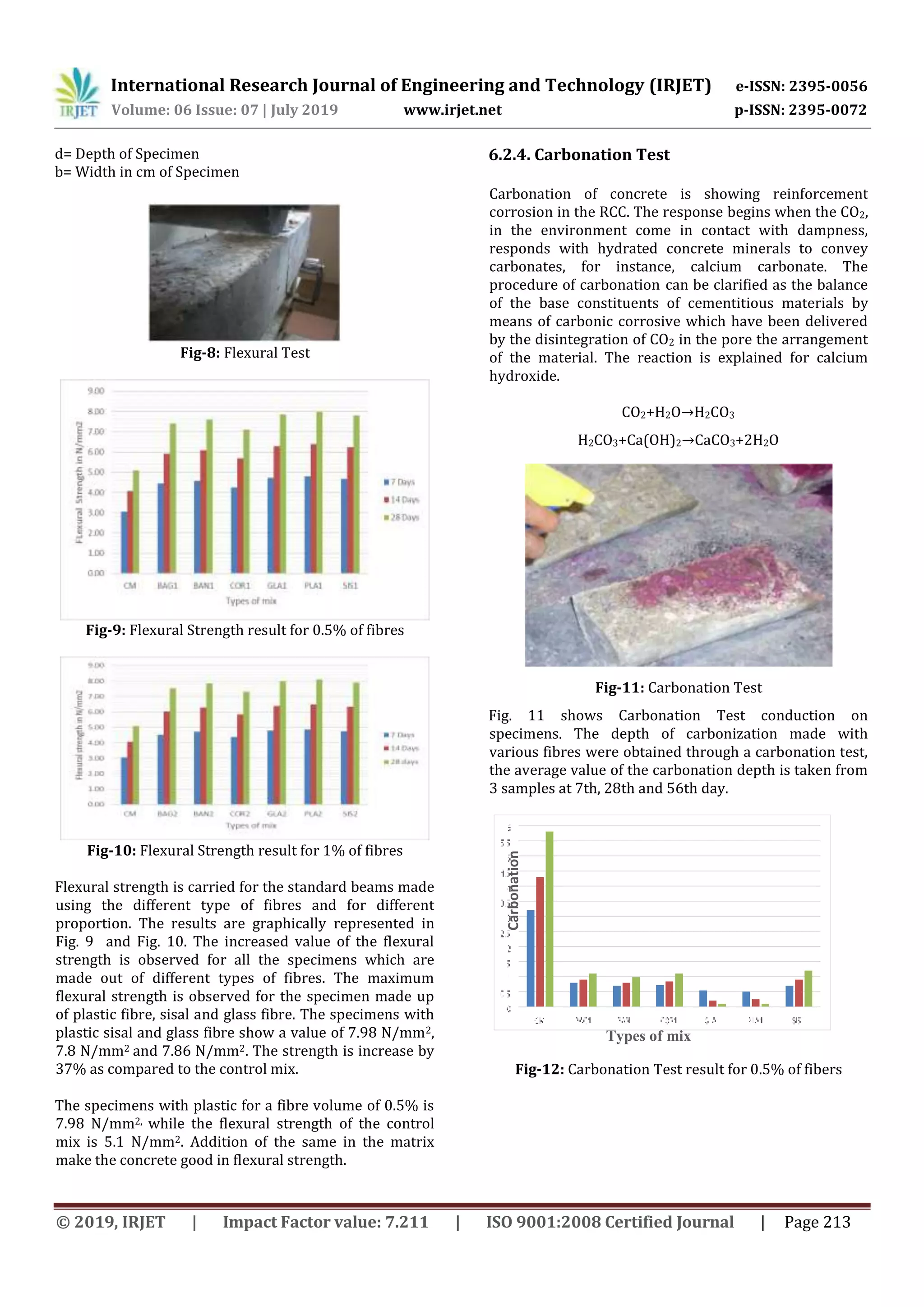
Fig-13: Carbonation Test result for 1% of fibers
Fig. 12 and Fig. 13 shows carbonation test results of
0.5% and 1% fibre. From the results it can be seen that
carbonation depth of concrete increased with age.
Control mix exhibited poor carbonation resistance
because connected pores existed inside the concrete
matrix. The addition of fibres prevented the
development of cracks. The fibres filled up the pores,
thus enhancing the carbonation resistance of concrete.
7. CONCLUSIONS
In this study an attempt is made to study the effect of
different types of fibre in the properties of concrete. The
basic constituent of the concrete is collected and test are
conducted to check the properties of the materials. Then
mix design is done for the M40 grade of concrete.
Different specimens were made with fibres such as coir,
banana, sisal, plastic, glass fibre and bagasse fibres. The
fibre volume is changed between 0.5% to 1%. After the
specified days of the curing, the test are conduct to study
the strength and durability properties of the concrete.
The important conclusion of the study is given in this
particular section.
1. Highest Compressive Strength of 62.2 N/mm2 is
obtained in case of addition of Glass fibers.
2. Split tensile strength and Flexural strength was
found to be highest by 5.21N/mm2 and 8.10
N/mm2 in case of Plastic Fiber.
3. Durability aspect also enhanced and is due to
the fact that fibers arrests the cracks, and
carbonation amount is reduced. It is only
0.3N/mm2 when Glass fiber is used in mix.
4. Workability properties of concrete is reduced
due to addition of fibers, which makes the mix
harsh. Increased volume of fiber reduces the
slump values. Least slump value obtained is
60mm for 1% addition of Banana Fiber.
5. The addition of higher fiber volume of 1%
enhances the mechanical and durability
properties.
6. The fibers are the better solution to resist the
cracking of the concrete which leads to the
sustainable development.
ACKNOWLEDGMENT
I express my sincere gratitude for the valuable guidance
and constant encouragement given by my project guide
and coordinator Mrs. Anupama Natesh, Assistant
Professor, Department of Civil Engineering, SDIT, who
showed great interest in project and gave guidance for
the proceedings to handle this project in a systematic
manner.
REFERENCES
[1] Anush K Chandrappa and Krishna Prapoorna
Bilgiri, “Flexural-fatigue characteristics of
pervious concrete: Statistical distributions and
model development”, Construction and Building
Materials Volume 153, Pages 1-15, 30 October
2017.
[2] Balte Sanjaykumar, and Prof. S. N. Daule, “Use of
Plastic Fiber in the Concrete”, SSRG
International Journal of Civil Engineering, pp 4-
7, 4.11(2017).
[3] Chouw et al, Majid Ali, Anthony Liu, Hou Sou,
“Mechanical and dynamic properties of coconut
fibre reinforced concrete”, Construction and
Building Materials, pp 814– 825, 30 (2012).
[4] Dang Hanh Nguyen, Nasim Sebaibi, “A modified
method for the design of pervious concrete mix”,
Construction and Building Materials, Volume 73
Pages 271-278, 30 October 2014.
[5] Dhawal Desai, “Pervious concrete – Effect of
material proportion on porosity”, International
journal of engineering and science ,Volume -
2,Issue-3,April 2010.
[6] Gaurav Uttam Shinde, Dr S.S Valunjkar,“An
experimental study on compressive strength,
void ratio and infiltration rate of pervious
concrete” ,International journal of Engineering
Research and technology ,Volume-4,Issue-
4,April 2015.
[7] Marwan Mostafa, Nasim Uddin, “Experimental
analysis of compressed Earth Block (CEB) with
Banana fibres resisting flexural and
compression forces”, Department of civil,
Construction and Enviornmental Engineering
University of Alabama at Birmingham.26 July
2016.
[8] Nalini Thakre,” Comparative Study on Strength
and Permeability of Pervious Concrete by Using
Nylon and Polypropylene Fibre”, IJCAT
International Journal of Computing and
Technology, Volume 1, Issue 4,ISSN : 2348 –
6090, May 2014.
Types of mix](https://image.slidesharecdn.com/irjet-v6i737-191030045455/75/IRJET-Comparative-Study-on-the-Strength-Parameters-of-Concrete-Made-using-Natural-and-Artificial-Waste-Fibres-6-2048.jpg)
![International Research Journal of Engineering and Technology (IRJET) e-ISSN: 2395-0056
Volume: 06 Issue: 07 | July 2019 www.irjet.net p-ISSN: 2395-0072
© 2019, IRJET | Impact Factor value: 7.211 | ISO 9001:2008 Certified Journal | Page 215
[9] Rui Zhong,Kay Wille, “ Compression response of
normal and high strength pervious concrete”,
construction and building materials, Volume
109 ,15 April 2016.
[10] S. Suresh, M. Sai Charan, “Strength and
behaviour of concrete by using natural and
artificial fibre combinations”, International
Journal of Civil Engineering and Technology
(IJCIET), Volume 8, Issue 4, pp. 1652–1658 April
2017.](https://image.slidesharecdn.com/irjet-v6i737-191030045455/75/IRJET-Comparative-Study-on-the-Strength-Parameters-of-Concrete-Made-using-Natural-and-Artificial-Waste-Fibres-7-2048.jpg)

This document summarizes a study on the strength properties of concrete made with natural and artificial waste fibers. The study aimed to compare the compressive strength, split tensile strength, flexural strength, durability, and workability of concrete containing different fiber types at 0.5% and 1% volume fractions. Materials tested included bagasse, banana, coir, glass, and plastic fibers. Results showed that fiber-reinforced concrete had higher strength properties than plain concrete and that strength generally increased with higher fiber content. Glass fiber concrete exhibited the highest strength while coir fiber concrete was the lowest but still stronger than plain concrete.


![[IJET-V2I5P1] Authors: Muthuraj, Ravi kumar.M, Keerthiprasad.K.S](https://cdn.slidesharecdn.com/ss_thumbnails/ijet-v2i5p1-161103102349-thumbnail.jpg?width=640&height=640&fit=bounds)


