Download as PDF, PPTX

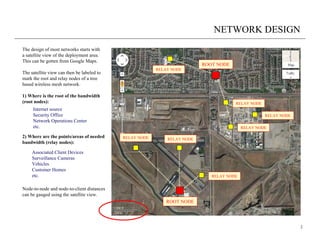
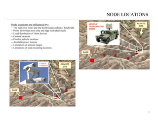
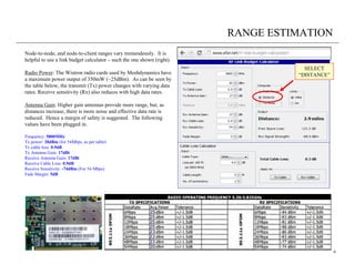
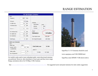
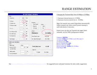

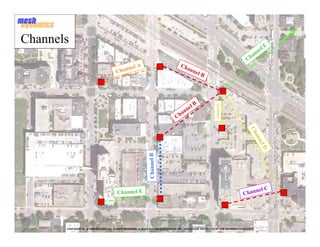
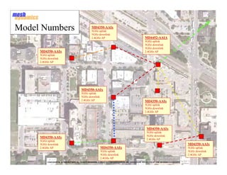
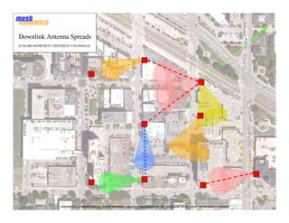
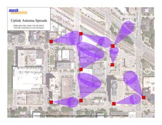
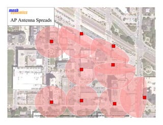
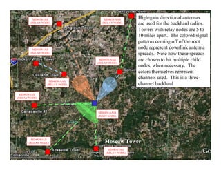
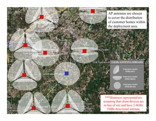
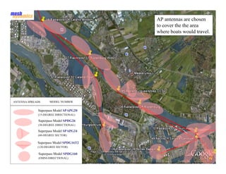
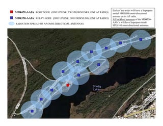
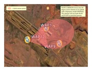
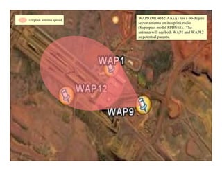
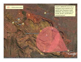
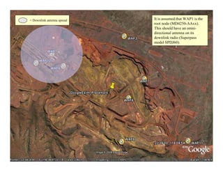
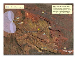
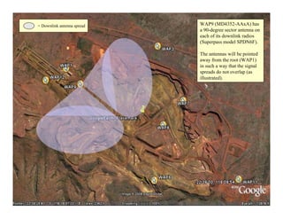
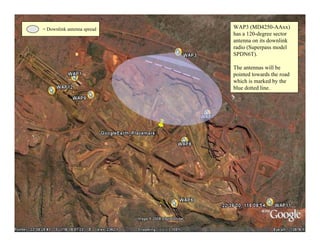
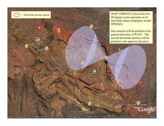
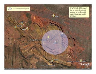
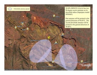

The document provides guidance on designing a wireless mesh network. It discusses beginning the design process with a satellite view of the deployment area to identify the root and relay nodes. Node locations are influenced by factors like the start and end points of bandwidth, points of needed bandwidth, and limitations of antennas and mounting locations. The document also provides information on estimating node ranges using a link budget calculator and selecting appropriate antennas based on the type of deployment, such as urban, rural, harbor, campground or mining scenarios. Recommendations are given for antenna selection and channel usage to avoid signal overlap.

![Military, Defense and Public Safety Mesh Networks [MeshDynamics]](https://cdn.slidesharecdn.com/ss_thumbnails/mdmilitarymesh-130203031024-phpapp02-thumbnail.jpg?width=640&height=640&fit=bounds)
![Mesh Networks in Underground Mining [MeshDynamics]](https://cdn.slidesharecdn.com/ss_thumbnails/meshminingjuly08-130203030519-phpapp02-thumbnail.jpg?width=640&height=640&fit=bounds)