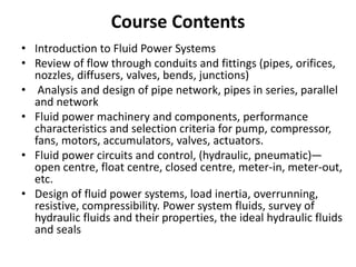
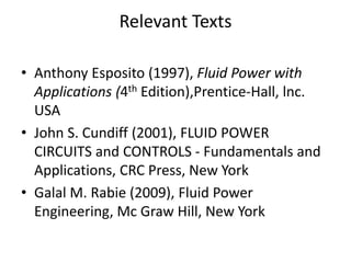
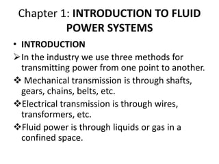
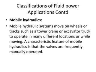
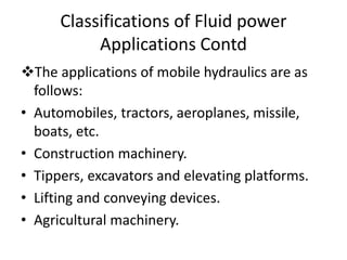
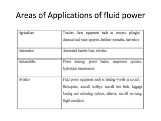
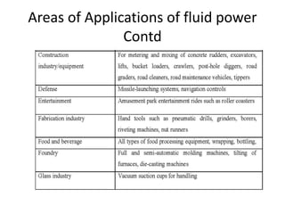
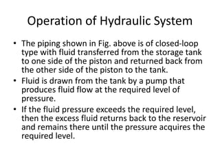
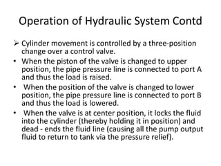
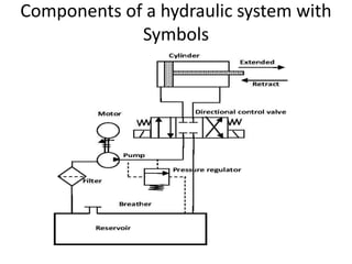
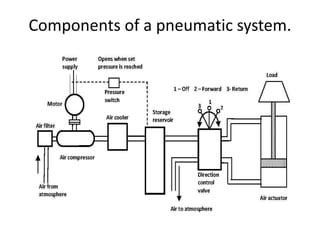
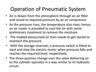
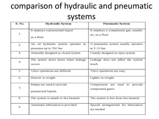
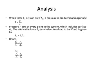
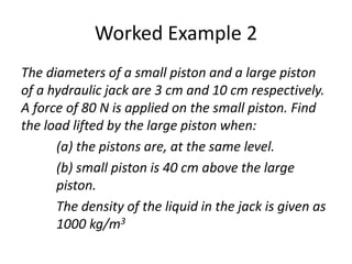
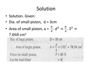
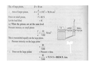
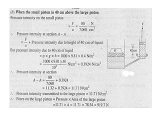
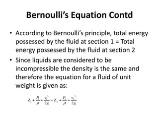
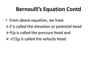
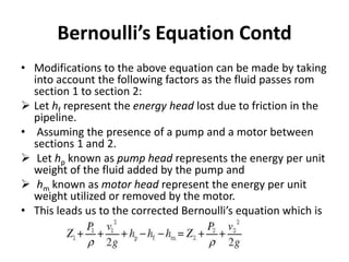
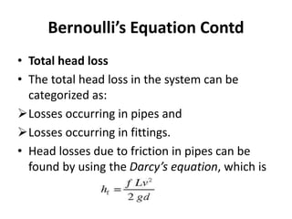
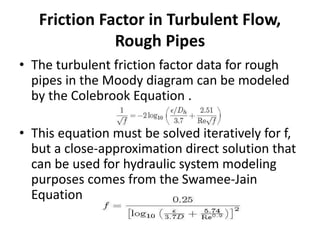
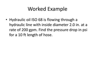
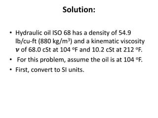
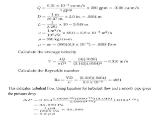
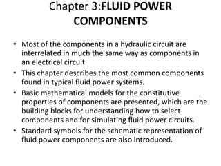
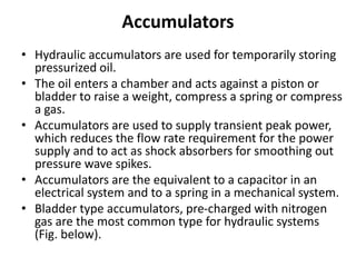
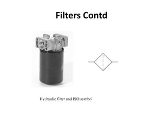
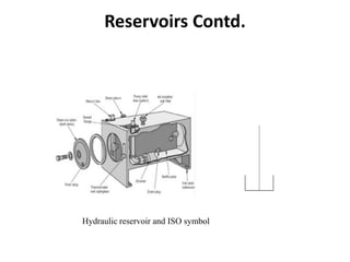
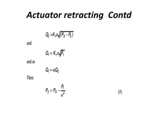
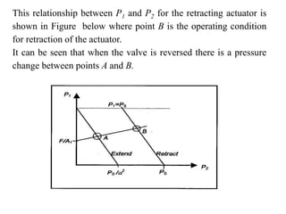
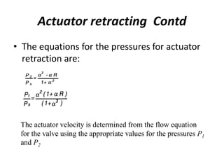
SlideShare a Scribd company logo
1 of 224
www.covenantuniversity.
Raising a new Generation of Leaders
FLUID POWER SYSTEMS (MCE 416)
CREDIT UNIT – 2
Dr. P. O. Babalola and Engr. J.O. Dirisu
Course Contents
• Introduction to Fluid Power Systems
• Review of flow through conduits and fittings (pipes, orifices,
nozzles, diffusers, valves, bends, junctions)
• Analysis and design of pipe network, pipes in series, parallel
and network
• Fluid power machinery and components, performance
characteristics and selection criteria for pump, compressor,
fans, motors, accumulators, valves, actuators.
• Fluid power circuits and control, (hydraulic, pneumatic)—
open centre, float centre, closed centre, meter-in, meter-out,
etc.
• Design of fluid power systems, load inertia, overrunning,
resistive, compressibility. Power system fluids, survey of
hydraulic fluids and their properties, the ideal hydraulic fluids
and seals
Relevant Texts
• Anthony Esposito (1997), Fluid Power with
Applications (4th Edition),Prentice-Hall, lnc.
USA
• John S. Cundiff (2001), FLUID POWER
CIRCUITS and CONTROLS - Fundamentals and
Applications, CRC Press, New York
• Galal M. Rabie (2009), Fluid Power
Engineering, Mc Graw Hill, New York
Chapter 1: INTRODUCTION TO FLUID
POWER SYSTEMS
• INTRODUCTION
In the industry we use three methods for
transmitting power from one point to another.
 Mechanical transmission is through shafts,
gears, chains, belts, etc.
Electrical transmission is through wires,
transformers, etc.
Fluid power is through liquids or gas in a
confined space.
• FLUID POWER SYSTEM DEFINED
• Fluid power is the technology that deals with the
generation, control and transmission of forces and
movement of mechanical element or system with the
use of pressurized fluids in a confined system.
• Fluid power system includes a hydraulic system (hydra
meaning water in Greek) and
• A pneumatic system (pneuma meaning air in Greek).
Oil hydraulic employs pressurized liquid petroleum oils
and synthetic oils, and
Pneumatic employs compressed air that is released to
the atmosphere after performing the work.
INTRODUCTION TO FLUID POWER
SYSTEMS Contd
• Reasons why water is not used in hydraulic power
transmission
• Commercially, pure water contains various chemicals (some
deliberately included) and also foreign matter, and unless
special precautions are taken when it is used, it is nearly
impossible to maintain valves and working surfaces in
satisfactory condition.
• In the cases where the hydraulic system is closed (i.e., the
one with a self-contained unit that serves one machine or
one small group of machines), oil is commonly used, thus
providing, in addition to power transmission, benefits of
lubrication not afforded by water as well as increased life
and efficiency of packings and valves.
INTRODUCTION TO FLUID POWER
SYSTEMS Contd
Classifications of Fluid power
Applications
• Fluid power applications can be classified into
two major segments:
• Stationary hydraulics:
Stationary hydraulic systems remain firmly
fixed in one position. The characteristic
feature of stationary hydraulics is that valves
are mainly solenoid operated.
Classifications of Fluid power
Applications Contd
The applications of stationary hydraulics are as follows:
• Production and assembly of vehicles of all types
• Machine tools and transfer lines.
• Lifting and conveying devices.
• Metal-forming presses.
• Plastic machinery such as injection-molding machines.
• Rolling machines.
• Lifts.
• Food processing machinery.
• Automatic handling equipment and robots.
• Mobile hydraulics:
• Mobile hydraulic systems move on wheels or
tracks such as a tower crane or excavator truck
to operate in many different locations or while
moving. A characteristic feature of mobile
hydraulics is that the valves are frequently
manually operated.
Classifications of Fluid power
Applications Contd
The applications of mobile hydraulics are as
follows:
• Automobiles, tractors, aeroplanes, missile,
boats, etc.
• Construction machinery.
• Tippers, excavators and elevating platforms.
• Lifting and conveying devices.
• Agricultural machinery.
Classifications of Fluid power
Applications Contd
Areas of Applications of fluid power
Contd
Areas of Applications of fluid power
Contd
Areas of Applications of fluid power
Contd
Areas of Applications of fluid power
Contd
Types of Fluid Systems
• There are actually two different types of fluid
systems: fluid transport and fluid power.
• Fluid transport systems:
• Their sole objective is the delivery of a fluid from
one location to another to accomplish some
useful purpose.
• Examples include pumping stations for pumping
water to homes, cross-country gas lines, and
systems where chemical processing takes place as
various fluids are brought together.
• Fluid power systems:
• Theses are designed specifically to perform
work. The work is accomplished by a
pressurized fluid bearing directly on an
operating cylinder or fluid motor, which, in
turn, provides the muscle to do the desired
work. Of course, control components are also
needed to ensure that the work is done
smoothly, accurately, efficiently, and safely.
Types of Fluid Systems Contd
Classification of Fluid Power Systems
• The fluid power system can be categorized as follows:
• 1. Based on the control system
• Open-loop system: There is no feedback in the open
system and performance is based on the characteristics
of the individual components of the system.
• Closed-loop system: This system uses feedback. The
output of the system is fed back to a comparator by a
measuring element. The comparator compares the
actual output to the desired output and gives an error
signal to the control element. A simple closed-loop
system uses servo valves and an advanced system uses
digital electronics.
• 2. Based on the type of control
• Fluid logic control: This type of system is controlled by
hydraulic oil or air. The system employs fluid logic
devices such as AND, NAND, OR, NOR, etc. Two types
of fluid logic systems are available:
(a) Moving part logic (MPL): These devices are
miniature fluid elements using moving parts such
as diaphragms, disks and poppets to implement
various logic gates.
(b) Fluidics: Fluid devices contain no moving parts and
depend solely on interacting fluid jets to
implement various logic gates.
Classification of Fluid Power Systems
• Electrical control:
• This type of system is controlled by electrical
devices. Four basic electrical devices are used for
controlling the fluid power systems: switches,
relays, timers and solenoids.
• These devices help to control the starting,
stopping, sequencing, speed, positioning, timing
and reversing of actuating cylinders and fluid
motors. Electrical control and fluid power work
well together where remote control is essential.
Classification of Fluid Power Systems
Contd
• Electronic control: This type of system is
controlled by microelectronic devices. The
electronic brain is used to control the fluid power
muscles for doing work.
• This system uses the most advanced type of
electronic hardware including programmable
logic control (PLC) or microprocessor (P). In the
electrical control, a change in system operation
results in a cumbersome process of redoing
hardware connections.
Classification of Fluid Power Systems
Contd
Hydrostatic and Hydrodynamic
Systems
• A hydrostatic system uses fluid pressure to
transmit power.
• Hydrostatics deals with the mechanics of still
fluids and uses the theory of equilibrium
conditions in fluid.
• The system creates high pressure, and through a
transmission line and a control element, this
pressure drives an actuator (linear or rotational).
• The pump used in hydrostatic systems is a
positive displacement pump.
• An example of pure hydrostatics is the transfer of
force in hydraulics.
• Hydrodynamic systems use fluid motion to
transmit power.
• Power is transmitted by the kinetic energy of the
fluid.
• Hydrodynamics deals with the mechanics of
moving fluid and uses flow theory.
• The pump used in hydrodynamic systems is a
non-positive displacement pump.
• An example of pure hydrodynamics is the
conversion of flow energy in turbines in
hydroelectric power plants.
Hydrostatic and Hydrodynamic
Systems Contd
Advantages of a Fluid Power System
 Fluid power systems are simple, easy to operate and
can be controlled accurately:
• Fluid power gives flexibility to equipment without
requiring a complex mechanism.
• Using fluid power, we can start, stop, accelerate,
decelerate, reverse or position large
forces/components with great accuracy using simple
levers and push buttons.
• For example, in Earth-moving equipment, bucket
carrying load can be raised or lowered by an operator
using a lever. The landing gear of an aircraft can be
retrieved to home position by the push button.
 Multiplication and variation of forces:
• Linear or rotary force can be multiplied by a fraction of
a kilogram to several hundreds of tons.
 Multifunction control:
• A single hydraulic pump or air compressor can provide
power and control for numerous machines using valve
manifolds and distribution systems.
• The fluid power controls can be placed at a central
station so that the operator has, at all times, a
complete control of the entire production line,
whether it be a multiple operation machine or a group
of machines.
• Such a setup is more or less standard in the steel mill
industry.
Advantages of a Fluid Power System
Contd
Low-speed torque:
• Unlike electric motors, air or hydraulic motors
can produce a large amount of torque while
operating at low speeds.
• Some hydraulic and pneumatic motors can
even maintain torque at a very slow speed
without overheating.
Constant force or torque:
• Fluid power systems can deliver constant
torque or force regardless of speed changes.
Advantages of a Fluid Power System
Contd
 Economical:
• Not only reduction in required manpower but
also the production or elimination of operator
fatigue, as a production factor, is an important
element in the use of fluid power.
 Low weight to power ratio:
• The hydraulic system has a low weight to
power ratio compared to electromechanical
systems. Fluid power systems are compact.
Advantages of a Fluid Power System
Contd
 Fluid power systems can be used where safety is of
vital importance:
• Safety is of vital importance in air and space travel, in
the production and operation of motor vehicles, in
mining and manufacture of delicate products.
• For example, hydraulic systems are responsible for the
safety of takeoff, landing and flight of aeroplanes and
space craft. Rapid advances in mining and tunneling
are the results of the application of modern hydraulic
and pneumatic systems.
Advantages of a Fluid Power System
Contd
Basic Components of a Hydraulic
System
• Hydraulic systems are power-transmitting
assemblies employing pressurized liquid as a
fluid for transmitting energy from an energy-
generating source to an energy-using point to
accomplish useful work.
• Figure below shows a simple circuit of a
hydraulic system with basic components.
Components of a hydraulic system
Functions of the components shown in Fig. above
are as follows:
• The hydraulic actuator is a device used to convert
the fluid power into mechanical power to do useful
work. The actuator may be of the linear type (e.g.,
hydraulic cylinder) or rotary type (e.g., hydraulic
motor) to provide linear or rotary motion,
respectively.
• The hydraulic pump is used to force the fluid from
the reservoir to rest of the hydraulic circuit by
converting mechanical energy into hydraulic energy.
• Valves are used to control the direction, pressure
and flow rate of a fluid flowing through the circuit.
• External power supply (motor) is required to
drive the pump.
• Reservoir is used to hold the hydraulic liquid,
usually hydraulic oil.
• Piping system carries the hydraulic oil from one
place to another.
• Filters are used to remove any foreign particles so
as keep the fluid system clean and efficient, as
well as avoid damage to the actuator and valves.
• Pressure regulator regulates (i.e., maintains) the
required level of pressure in the hydraulic fluid.
•
Components of a hydraulic system
Contd
Operation of Hydraulic System
• The piping shown in Fig. above is of closed-loop
type with fluid transferred from the storage tank
to one side of the piston and returned back from
the other side of the piston to the tank.
• Fluid is drawn from the tank by a pump that
produces fluid flow at the required level of
pressure.
• If the fluid pressure exceeds the required level,
then the excess fluid returns back to the reservoir
and remains there until the pressure acquires the
required level.
 Cylinder movement is controlled by a three-position
change over a control valve.
• When the piston of the valve is changed to upper
position, the pipe pressure line is connected to port A
and thus the load is raised.
• When the position of the valve is changed to lower
position, the pipe pressure line is connected to port B
and thus the load is lowered.
• When the valve is at center position, it locks the fluid
into the cylinder (thereby holding it in position) and
dead - ends the fluid line (causing all the pump output
fluid to return to tank via the pressure relief).
Operation of Hydraulic System Contd
Hydraulic System Using Symbols
• In industry, a machine designer conveys the design of
hydraulic systems using a circuit diagram.
• Figure below shows the components of the hydraulic
system using symbols.
• The working fluid, which is the hydraulic oil, is stored in a
reservoir. When the electric motor is switched ON, it
runs a positive displacement pump that draws hydraulic
oil through a filter and delivers at high pressure.
• The pressurized oil passes through the regulating valve
and does work on actuator. Oil from the other end of the
actuator goes back to the tank via return line.
• To and fro motion of the cylinder is controlled using
directional control valve.
Components of a hydraulic system with
Symbols
Comparison of Hydraulic System and
Electrical System
 The hydraulic system discussed above can be broken
down into four main divisions that are analogous to the
four main divisions in an electrical system.
• The power device parallels the electrical generating
station.
• The control valves parallel the switches, resistors,
timers, pressure switches, relays, etc.
• The lines (pipe and hose) in which the fluid power
flows parallel the electrical lines.
• The fluid power motor (whether it is a rotating or a
non- rotating cylinder or a fluid power motor) parallels
the solenoids and electrical motors.
Basic Components of a Pneumatic
System
• A pneumatic system carries power by
employing compressed gas, generally air, as a
fluid for transmitting energy from an energy-
generating source to an energy-using point to
accomplish useful work.
• Figure below shows a simple circuit of a
pneumatic system with basic components.
Components of a pneumatic system.
Functions of Pneumatic Components
 The functions of various components shown in Fig. above
are as follows:
• The pneumatic actuator converts the fluid power into
mechanical power to perform useful work.
• The compressor is used to compress the fresh air drawn
from the atmosphere.
• The storage reservoir is used to store a given volume of
compressed air.
• The valves are used to control the direction, flow rate and
pressure of compressed air.
• External power supply (motor) is used to drive the
compressor.
• The piping system carries the pressurized air from one
location to another.
Operation of Pneumatic System
• Air is drawn from the atmosphere through an air filter
and raised to required pressure by an air compressor.
• As the pressure rises, the temperature also rises; hence,
an air cooler is provided to cool the air with some
preliminary treatment to remove the moisture.
• The treated pressurized air then needs to get stored to
maintain the pressure.
• With the storage reservoir, a pressure switch is fitted to
start and stop the electric motor when pressure falls and
reaches the required level, respectively.
• The three-position change over the valve delivering air
to the cylinder operates in a way similar to its hydraulic
circuit.
comparison of hydraulic and pneumatic
systems
2.0 Fluid Power Basics - Review of
flow through conduit
• INTRODUCTION
• Fluid power systems are designed using all the principles learned in
fluid mechanics.
• The underlying postulates of fluid mechanics are:
 For a particular position within a fluid at rest, the pressure is the
same in all directions. This follows directly from Pascal’s Law.
 A second postulate states that fluids can support shear forces only
when in motion.
• These two postulates define the characteristics of the fluid media
used to transmit power and control motion.
• Traditional concepts such as static pressure, viscosity, momentum,
continuity, Bernoulli’s equation, and head loss are used to analyze
the problems encountered in fluid power systems.
Pressure and Flow
• Fluid power is characterized by two main variables,
 Pressure and
 flow,
• whose product is power.
• Pressure P is force per unit area and
• Flow Q is volume per time.
• Because pneumatics uses compressible gas as the fluid,
mass flow rate Qm is used for the flow variable when
analyzing pneumatic systems.
• For hydraulics, the fluid is generally treated as
incompressible, which means ordinary volume flow Q
can be used.
Pressure – Units and Measurement
• Table below shows how pressure units are
related.
Pressure – Units and Measurement
• Pressure is an across type variable, which means that it
is always measured with respect to a reference just like
voltage in an electrical system.
• As shown in Figure below, the pressure across a fluid
power element such as a pump or a valve, is the
pressure differential from one side to the other
• The pressure at a point, for example the pressure of
fluid at one point in a hose, it is always with respect to
a reference pressure.
• Reporting absolute pressure means that the pressure is
measured with respect to a perfect vacuum.
Pressure is Measured with Respect to
a Reference
Pressure at a Point in a Liquid
• The pressure at any point in a fluid at rest, is
given by the Hydrostatic law, which states that
the rate of increase of pressure in a vertically
downward direction must be equal to the specific
weight of the fluid at that point.
• The vertical height of the free surface above any
point in a liquid at rest is known as the pressure
head. This implies that the pressure (called head
pressure) at any point in a liquid is given by the
equation:
• P = ρ gh
Atmospheric, absolute, gage pressure
and vacuum
• Atmospheric pressure
 The earth is surrounded by an envelope of air called
the atmosphere, which extends upwards from the
surface of the earth. Air has mass and due to the effect
of gravity exerts a force called weight. The force per
unit area is called pressure. This pressure exerted on
the earth’s surface is known as atmospheric pressure.
• Gage pressure
 Most pressure-measuring instruments measure the
difference between the pressure of a fluid and the
atmospheric pressure. This is referred to as gage
pressure.
• Absolute pressure
Absolute pressure is the sum of the gage pressure
and the atmospheric pressure.
• Vacuum
If the pressure is lower than the atmospheric
pressure, its gage pressure is negative and the
term vacuum is used when the absolute pressure
is zero (i.e. there is no air present whatsoever) i.e
P = 0
Atmospheric, absolute, gage pressure
and vacuum
Pascal’s law
• The underlying principle of how fluids transmit
power is revealed by Pascal’s law.
• Pascal’s law states that the pressure applied to a
confined fluid is transmitted undiminished in all
directions.
• This law forms the basis for understanding the
relationship between force, pressure and area,
which can be mathematically expressed as:
• Pressure =
𝐹𝑜𝑟𝑐𝑒
𝐴𝑟𝑒𝑎
Example of Force Transmission
The transmitted pressure acts with equal force on every unit area of the containing
vessel and in a direction at right angle to the surface of the vessel exposed to the
liquid.
As pressure acts equally in all directions, the shape of the container is irrelevant.
Analysis
• When force F1 acts on area A1, a pressure is produced of magnitude
P =
𝐹1
𝐴1
• Pressure P acts at every point in the system, which includes surface
A2. The attainable force F2 (equivalent to a load to be lifted) is given
by
F2 = P.A2
• Hence,
𝐹1
𝐴1
=
𝐹2
𝐴2
or,
𝐹2
𝐹1
=
𝐴2
𝐴1
Worked Examples
• A hydraulic press has a ram of 30 cm diameter
and a plunger of 4.5 cm diameter. Find the
weight lifted by the hydraulic press when the
force applied at the plunger is 500 N.
Solution
Worked Example 2
The diameters of a small piston and a large piston
of a hydraulic jack are 3 cm and 10 cm respectively.
A force of 80 N is applied on the small piston. Find
the load lifted by the large piston when:
(a) the pistons are, at the same level.
(b) small piston is 40 cm above the large
piston.
The density of the liquid in the jack is given as
1000 kg/m3
Solution
• Solution. Given:
• Dia. of small piston, d = 3cm
• Area of small piston, a =
𝜋
4
. 𝑑2
=
𝜋
4
. 32
=
7.068 cm2
Application of Pascal’s law
• Two basic applications of Pascal’s law: the hydraulic jack and
the air-to-hydraulic booster are considered.
• Hand- Operated Hydraulic jack System
 This system uses a piston-type hand pump to power a single
acting hydraulic cylinder as illustrated in Figure below.
 A hand force is applied at point ‘A’ of handle ‘ABC’, which
pivots about point ‘C’.
 The piston rod of the hand pump is pinned to the input
handle at point ‘B’.
 The hand pump contains a cylinder for aiding the up and
down movement.
 When the handle is pulled, the piston moves up, thereby
creating a vacuum in the space below it. As a result of this,
the atmospheric pressure forces the oil to leave the oil tank
and flow through check valve 1. This is the suction process.
• When the handle is pushed down, oil is ejected from the hand
pump and flows through the check valve 2. Oil now enters the
bottom of the load cylinder. The load cylinder is similar in
construction to the pump cylinder.
• Pressure builds up below the load piston as oil is ejected from the
pump.
• From Pascal’s law, we know that the pressure acting on the load
piston is equal to the pressure developed by the pump below its
piston.
• Thus each time the handle is operated up and down, a specific
volume of oil is ejected from the pump to lift the load cylinder to
a given distance against its load resistance.
• The bleed valve is a hand-operated valve which when opened,
allows the load to be lowered by bleeding oil from the load
cylinder back to the oil tank. This cylinder is referred to as single
Hand-operated hydraulic jack system
Air-to-hydraulic Pressure Booster
• Air-to-hydraulic pressure booster is a device
used to convert workshop air into a higher
hydraulic pressure needed for operating
cylinders requiring small to medium volumes
of high-pressure oil (See Fig. below).
• It consists of an air cylinder with a large
diameter driving a small diameter hydraulic
cylinder.
• Any workshop equipped with an airline can
easily obtain hydraulic power from an air-to-
hydraulic booster hooked into the airline.
Air-to-hydraulic Pressure Booster
• Figure below shows an application of the air-to-
hydraulic booster.
• Here the booster is seen supplying high-pressure oil to
a hydraulic cylinder used to clamp a work piece to a
machine tool table.
• The pressure ratio of the pressure booster can be
determined as follows:
• Pressure ratio =
𝑂𝑢𝑡𝑝𝑢𝑡 𝑜𝑖𝑙 𝑝𝑟𝑒𝑠𝑠𝑢𝑟𝑒
𝐼𝑛𝑝𝑢𝑡 𝑜𝑖𝑙 𝑝𝑟𝑒𝑠𝑠𝑢𝑟𝑒
=
𝐴𝑟𝑒𝑎 𝑜𝑓 𝑎𝑖𝑟 𝑝𝑖𝑠𝑡𝑜𝑛
𝐴𝑟𝑒𝑎 𝑜𝑓 ℎ𝑦𝑑𝑟𝑎𝑢𝑙𝑖𝑐 𝑝𝑖𝑠𝑡𝑜𝑛
Air-to-hydraulic Pressure Booster
Manufacturing application of an air-to-hydraulic booster
FLOW
• Flow is the term used to describe the movement
of a hydraulic medium through a circuit.
• Flow occurs when there is a difference in
pressure between two points.
• In a hydraulic circuit, flow is created by a device
such as a pump.
• A pump exerts push effort on a fluid.
• Flow rate is the volume or mass of fluid passing
through a conductor over a given unit of time: an
example would be gallons per minute (gpm).
• Flow can be measured in two ways:
velocity and
flow rate.
• The velocity of a fluid in a confined circuit is the
speed at which it moves through it. It is measured
in feet per second (fps).
• Flow rate is the volume of fluid that passes a
point in a hydraulic circuit in a given time. It is
measured in gallons per minute (gpm).
FLOW CONTD
Flow – Units and Measurements
• Volume flow rate is reported in gallons per
minute, liters per minute and cubic meters per
second (SI unit).
• Table below shows how flow rate units are
related.
• Flow is a through type variable, which means
it is volume of fluid flowing through an
imaginary plane at one location.
• Like current in an electrical system, there is
no reference point.
• Flow is measured with a flow meter placed in-
line with the fluid circuit.
• Figure below shows some common types of
flow meters.
Flow – Units and Measurements
Contd
Types of flowmeters. Top row: turbine, digital paddle, variable area. Bottom
row is a dual-rotor turbine flowmeter with a cutaway.
Hydrostatics, Hydrokinetics and
Hydrodynamics
• The study of science dealing with liquids at rest is
referred to as Hydrostatics.
• The study of liquids in motion can be discussed
under two headings, Hydrokinetics and
Hydrodynamics.
• Hydrokinetics deals with the motion of fluid
particles without considering the forces causing
the motion.
• Hydrodynamics is the study of fluid motion that
includes the forces causing the flow.
Types of fluid flow
• Fluid flow can be classified as follows:
Steady and unsteady flows
Uniform and non-uniform flows
Laminar and turbulent flows
Rotational and non-rotational flows.
Steady flow and Unsteady flow
• Fluid flow is said to be steady if at any point in
the flowing fluid, important characteristics such
as pressure, density, velocity, temperature, etc.
that are used to describe the behavior of a fluid,
do not change with time. In other words, the rate
of flow through any cross section of a pipe in a
steady flow is constant.
• Unsteady flow is that type of flow, in which the
fluid characteristics change with respect to time
or in other words, the rate of flow through any
cross-section of a pipe is not constant.
Uniform flow and Non- uniform flow
• Flow is said to be uniform, when the velocity of flow
does not change either in magnitude or in direction at
any point in a flowing fluid, for a given time. For
example, the flow of liquids under pressure through
long pipelines with a constant diameter is called
uniform flow.
• Flow is said to be non-uniform, when there is a change
in velocity of the flow at different points in a flowing
fluid, for a given time. For example, the flow of liquids
under pressure through long pipelines of varying
diameter is referred to as non-uniform flow.
Laminar flow
• A flow is said to be laminar if the fluid
particles move in layers such that one layer of
the fluid slides smoothly over an adjacent
layer.
• The viscosity property of the fluid plays a
significant role in the development of a
laminar flow.
• The flow pattern exhibited by a highly viscous
fluid may in general be treated as laminar flow
Laminar Flow
• Flow is said to be laminar if the layers of fluid
particles remain parallel as the flow moves
along the conductor.
Turbulent flow
• Flow is said to be turbulent if the fluid layers
break down as the flow moves along the
conductor.
• If the velocity of flow increases beyond a
certain value, the flow becomes turbulent.
Turbulent Flow Contd
• Due to greater energy losses, turbulent flow is
generally avoided in hydraulic systems.
• Some of the causes for turbulent flow in a
hydraulic system are:
Roughness of pipelines
Obstructions to flow
Degree of curvature of bends
Increase in the number of bends.
 Reynolds Number
• In a hydraulic system, it is important to know
whether the flow pattern inside a pipe is laminar
or turbulent and also to determine the conditions
that govern the transition of the flow from
laminar to turbulent.
• This is where Reynolds number holds much
significance. The Reynolds number is a
dimensionless ratio of inertia force to viscous
force.
Turbulent Flow Contd
• Reynolds number ‘Re’ is given by the expression:
• 𝑅𝑒 =
𝜌𝑢𝑑
𝜇
=
𝑢𝑑
𝜈
Where 𝝂 =
𝜇
𝜌
• If Re is lesser than 2000, the flow is said to be
laminar
• If Re is greater than 4000, the flow is said to be
turbulent.
• Any value of Re ranging between 2000 and 4000
such flow is in transition.
Turbulent Flow Contd
• Re = Reynolds number
• µ =kinematic viscosity
• v =dynamic viscosity
• d = diameter
•  = density
• u = velocity
Rotational flow and Non-rotational
flow
• A flow is said to be rotational if the fluid
particles moving in the direction of flow rotate
around their own axis.
• If the fluid particles flowing in a laminar
pattern do not rotate about their axis, then
the flow is said to be non-rotational.
CONDUIT FLOW
• Conduit flow properties can be analyzed using
basic principles of fluid mechanics.
• The Reynolds number, the non-dimensional
ratio of inertial to viscous forces, is commonly
used to characterize the flow in pipes.
• Bernoulli’s equation is also used to analyse
flow in hydraulic system.
Bernoulli’s Equation
• Bernoulli’s equation is one of the vital tools
employed in the analysis of hydraulic systems.
• Bernoulli’s equation basically enunciating the
principle of conservation of energy which states
that in a liquid flowing continuously, the sum
total of static pressure and velocity energy
heads is constant at all sections of the flow.
• The law as applied to a hydraulic pipeline is
illustrated in Figure below.
Pipeline for deriving Bernoulli’s equation
Bernoulli’s Equation Contd
• According to Bernoulli’s principle, total energy
possessed by the fluid at section 1 = Total
energy possessed by the fluid at section 2
• Since liquids are considered to be
incompressible the density is the same and
therefore the equation for a fluid of unit
weight is given as:
Bernoulli’s Equation Contd
• From above equation, we have
Z is called the elevation or potential head
P/ρ is called the pressure head and
 v2/2g is called the velocity head.
Bernoulli’s Equation Contd
• Modifications to the above equation can be made by taking
into account the following factors as the fluid passes rom
section 1 to section 2:
 Let hf represent the energy head lost due to friction in the
pipeline.
• Assuming the presence of a pump and a motor between
sections 1 and 2.
 Let hp known as pump head represents the energy per unit
weight of the fluid added by the pump and
 hm known as motor head represent the energy per unit
weight utilized or removed by the motor.
• This leads us to the corrected Bernoulli’s equation which is
Bernoulli’s Equation Contd
• Total head loss
• The total head loss in the system can be
categorized as:
Losses occurring in pipes and
Losses occurring in fittings.
• Head losses due to friction in pipes can be
found by using the Darcy’s equation, which is
Bernoulli’s Equation Contd
Frictional losses in laminar flow
• For laminar flow, the friction factor ‘f ’ is given
by
Frictional losses in turbulent flow
• Unlike in the case of laminar flow, the friction
factor cannot be represented by a simple formula
for turbulent flow.
• This is due to the fact that the movement of fluid
particles in a turbulent flow is random and
fluctuating in nature.
• Here the friction factor has been found to depend
not only on the Reynolds number but also the
relative roughness of the pipe. This relative
roughness is given by:
Pressure Losses in Conduits
• The pressure losses in straight pipe and hoses
contribute to the overall efficiency of a fluid
power system.
• The losses can be estimated using the Darcy-
Weisbach equation
• There are different formulas for the friction factor
depending on the Reynolds number and the surface
roughness of the pipe or hose.
• The experimental determination of friction factors are
shown on the classic Moody Diagram (Fig. below) that
plots the friction factor as a function of Reynolds
number for a range of surface roughness of round
pipes.
• The diagram shows that for laminar flow, friction factor
is independent of roughness.
• For turbulent flow, the friction factor, and therefore
pressure losses, depend both on the Reynolds number
and the roughness of the pipe, except at high Reynolds
numbers where losses depend only on the roughness.
Pressure Losses in Conduits
Moody Diagram showing the experimental friction factor for pipes
Pressure Loss in Laminar Flow
• The pressure loss in a pipe with laminar flow can
be calculated as
• Converting average velocity to the more
convenient fluid flow rate (V = 4Q/πD2) yields
• This equation shows that for smooth flow, the
pressure drop is proportional to the flow rate Q.
Pressure Drop in Turbulent Flow,
Smooth Pipes
• For turbulent flow, the friction factor depends
both on the Reynolds number and the surface
roughness of the pipe.
• In most fluid power systems the pipes and
hoses have smooth interiors and the friction
factor for smooth pipes can be used.
• Under these conditions, an empirical
approximation, derived by Blasius can be used
to calculate the friction factor i.e
• The pressure loss in a smooth pipe with
turbulent flow is
• The pressure loss is almost, but not quite,
proportional to the square of the flow rate,
thus a pipe with turbulent flow acts like a
nonlinear resistor.
Pressure Drop in Turbulent Flow,
Smooth Pipes
Friction Factor in Turbulent Flow,
Rough Pipes
• The turbulent friction factor data for rough
pipes in the Moody diagram can be modeled
by the Colebrook Equation .
• This equation must be solved iteratively for f,
but a close-approximation direct solution that
can be used for hydraulic system modeling
purposes comes from the Swamee-Jain
Equation
Worked Example
• Hydraulic oil ISO 68 is flowing through a
hydraulic line with inside diameter 2.0 in. at a
rate of 200 gpm. Find the pressure drop in psi
for a 10 ft length of hose.
Solution:
• Hydraulic oil ISO 68 has a density of 54.9
lb/cu-ft (880 kg/m3) and a kinematic viscosity
𝝂 of 68.0 cSt at 104 oF and 10.2 cSt at 212 oF.
• For this problem, assume the oil is at 104 oF.
• First, convert to SI units.
This indicates turbulent flow. Using Equation for turbulent flow and a smooth pipe gives
the pressure drop
Worked Example2
• For the hydraulic system of below, the following metric data (which
are equivalent to the English system data) are given:
1. The pump is adding 5 hp (3730 W) to the fluid.
2. Pump flow is 0.001896 ml/s.
3. The pipe has a 0.0254-m inside diameter.
4. The specific gravity of oil is 0.9.
5. The kinematic viscosity of oil is 100 cS .
6. The elevation difference between stations 1 and 2 is 6.096 m.
7. Pipe lengths are as follows: 1-ft length = 0.305 m, 4-ft length =
1.22 m; and 16-ft length = 4.88 m.
• Find the pressure available at the inlet to the hydraulic motor
(station 2). The pressure at the oil top surface level in the hydraulic
tank is atmospheric (0 Pa gage). The head loss HL due to friction
between stations 1 and 2 is not given.
Hydraulic system for Example 2
Solution
• We need to convert kinematic viscosity in cS
to the appropriate units in the SI metric
system (v = m2/s).
Solution Contd
• . Since there is no hydraulic motor between
stations l and 2, Hm = 0.
• Also v1 = 0 and P1/γ = 0 (the oil tank is vented
to the atmosphere).
• Also Z2 - Z1 = 6.096 m per given input data. To
make use of Bernoulli's equation, let's first
solve for v2:
Solution Contd
The Reynolds number can now be found:
Since the flow is laminar, the friction factor can
be found directly from the Reynolds number:
Solution Contd
Chapter 3:FLUID POWER
COMPONENTS
• Most of the components in a hydraulic circuit are
interrelated in much the same way as components in
an electrical circuit.
• This chapter describes the most common components
found in typical fluid power systems.
• Basic mathematical models for the constitutive
properties of components are presented, which are the
building blocks for understanding how to select
components and for simulating fluid power circuits.
• Standard symbols for the schematic representation of
fluid power components are also introduced.
3.1 Hydraulic Cylinders
• Hydraulic Cylinders convert fluid power pressure
and flow to mechanical translational power force
and velocity (Fig. below).
• Cylinders are linear actuators that can push and
pull, and when mounted around a joint, for
example, as is done in an excavator, can actuate
rotary motion.
• Cylinders come in single acting (push only), single
acting with spring return and double-acting
(push-pull).
Hydraulic cylinder
Cut-away view of a welded body, industrial double-acting hydraulic cylinder.
ISO schematic symbol for a double-acting cylinder
Dynamic Model used for Cylinder
Simulations
• The dynamic model used for most cylinder
simulations simply captures the pressure-force
transformation and sometimes includes the
cylinder friction and leakage around the piston
seal.
• The defining equations for an ideal, friction-
free, leakless cylinder are:
F = PA
V = Q/A
• The piston force depends on the difference in
pressure across the piston, taking into account
the area on each side.
• Referring to Figure below the piston force is:
FP = P1Acap - P2Arod (*)
• where all pressures are gauge pressures with
respect to atmospheric pressure.
Dynamic Model used for Cylinder
Simulations Contd.
Forces on a cylinder
(**)
Overall Efficiency of a Cylinder
• The overall efficiency of a cylinder is given by
the ratio of the output mechanical power to
the input fluid power:
• where Pi and Qi refer to either the cap or rod
side depending on whether the piston is
pushing or pulling.
• Cylinder efficiency can be split into two parts:
 the force efficiency
the volumetric efficiency
• With the overall efficiency being the product
η = ηf ηv.
Using these relations, Equations (*) and (**)
can be modified for a non-ideal cylinder with
friction and leakage
Pumps and Motors
• Hydraulic pumps supply energy to the system, converting
the torque and velocity of an input shaft to pressure and
flow of the output fluid.
• Hydraulic motors are the rotary equivalent of cylinders.
• Pressurized oil flows through the motor and produces
rotation of the output shaft.
• A motor is simply a pump driven in reverse (fluid flow in,
shaft rotation out versus shaft rotation in and fluid flow
out)
• Many devices can act both as a pump and a motor, much
the same way that a DC permanent magnet motor can act
both as a motor and a generator.
• *compressor, inverter,heat pump(condenser evaporator), speaker-microphone
• The common types of pumps and motors are
 gear and vane pumps and motors and
 axial and radial piston pumps and motors.
• Fixed displacement devices rotate a fixed amount for a
fixed volume of fluid.
• Variable displacement devices have a mechanical or fluid
power control port that can be used to vary the relation
between fluid volume and shaft rotation, and are
essentially a variable transmission between fluid and
mechanical rotary power.
• Pumps are generally driven by electric motors in industrial
applications and diesel engines in mobile applications.
• The symbols for fixed displacement, uni-directional pumps
and motors are shown in Figure below.
Pumps and Motors Contd.
Pumps, motors and their schematic symbols. The difference between the two symbols is
the direction that the triangle is pointing; out for pumps, in for motors
Model for Pump and Motor
• Ideal pumps and motors are defined by the
relations between fluid pressure P and flow Q
and shaft torque T and velocity ω.
• For an ideal motor, input and output power is
conserved.
• If ∆P is the pressure difference across the
pump or motor, then the power balance for a
pump or motor is:
• If the volumetric displacement of the motor or
pump is Dv, typically expressed in cubic
in./rad, then the relations relating fluid to
mechanical are:
Model for Pump and Motor Contd.
Efficiency Equations for Pump & Motor
• Real pumps and motors are not 100% efficient
and, like cylinders, have an overall efficiency η,
which is made up of volumetric ηv and
mechanical ηm
Overall Efficiency : η = ηv . ηm
Control Valves
• Control valves are essential and appear in all fluid
power systems.
• Valves are sometimes categorized by function,
which includes
Directional control valves for directing fluid flow
to one or the other side of a cylinder or motor,
Pressure control valves for controlling the fluid
pressure at a point and flow control valves for
limiting the fluid flow rate in a line, which in turn
limits the extension or retraction velocities of a
piston.
• Valves can also be characterized by the number of ports on the
valve for connecting input and output lines and by the number of
operating positions that the valve can assume.
• For example, a 3-way, 2-position valve commonly found in
pneumatic systems has three ports for connecting supply line,
exhaust or reservoir line and output line to the cylinder and two
positions.
• On/off valves can only be in the states defined by their positions
while proportional valves are continuously variable and can take on
any position in their working range.
• A servo valve is a proportional valve with an internal closed-loop
feedback mechanism to maintain precise control over the valve
behavior.
• Example valves are shown in Figure below.
Control Valves Contd.
Types of control valves, Left to right: hand-operated directional valve for a log splitter.
On-off miniature, solenoid actuated pneumatic valve. Precision proportional pneumatic
valves. High precision, flapper-nozzle hydraulic servo valve.
Dynamic Models for Valves
• The basic equation for a valve is the orifice
equation given as:
• where Cd is valve coefficient, A is the area of
the valve opening and P is the pressure drop
across the valve.
• To simplify analysis, the orifice equation can
be linearized about a nominal operating point
at the x = 0 valve position with leakage flow Q0
Dynamic Models for Valves Contd.
Valve Symbols
• Because there are so many types of valves,
their symbols can be complex.
• Some of the more basic symbols are shown
below.
Basic symbols for fluid power valves. The number of squares is the number of valve
positions. Image (a) represents a three-position valve and (b) represents a two-position
valve. The number of connection points on the symbol is the number of ports (”‘ways”’) for
the valve. Image (c) represents a 3-way, 2-position valve or ”‘3/2 valve”’ for short.
Valve Symbols Contd.
A 4/2 valve with four connection points and two positions. In the nominal, unactuated
state, supply line P connects to working line A and working line B connects to return
(tank) line T. In the actuated state, the valve slides to the right and supply line P connects
to working line B and working line A connects to return line T.
Valve actuation symbols. Left to right: push-button, lever, spring return, solenoid, pilot-
line.
Valve Symbols Contd.
(a) Pushbutton hydraulic 4/2 valve. In the nominal position, the cylinder is held in the
retracted position because supply line P is connected to the rod side. When the button is
pushed, the rod extends because supply line P is now connected to the cap side. When the
button is released, the valve spring returns the valve to the nominal position, retracting the
rod. (b) Solenoid 4/3 valve with center closed position and spring return to center. A
computer can control extension and retraction of the cylinder by actuating the valve
solenoids. (c) Same as b, but with a continuously variable proportional valve.
Accumulators
• Hydraulic accumulators are used for temporarily storing
pressurized oil.
• The oil enters a chamber and acts against a piston or
bladder to raise a weight, compress a spring or compress
a gas.
• Accumulators are used to supply transient peak power,
which reduces the flow rate requirement for the power
supply and to act as shock absorbers for smoothing out
pressure wave spikes.
• Accumulators are the equivalent to a capacitor in an
electrical system and to a spring in a mechanical system.
• Bladder type accumulators, pre-charged with nitrogen
gas are the most common type for hydraulic systems
(Fig. below).
Accumulators Contd
Accumulator and ISO symbol.
• The capacity of a fluid capacitor is defined by
its change in volume divided by its change in
pressure
• 𝑪𝒇 =
∆𝑽
∆𝑷
Accumulators Contd
• Change in volume per time is flow rate and change in pressure per time is the
derivative of pressure. This leads to the constitutive law for a linear fluid
capacitor
𝑸 = 𝑪𝒇. 𝑷
• Another type of accumulator is a cylinder with
the fluid pushing on one side of the piston against
a stiff spring on the other side of piston.
• For these spring-loaded piston accumulators the
capacitance is
• 𝑪𝒇 =
𝑨𝟐
𝑲
• where A is the area of the piston and K is the
spring constant.
Accumulators Contd.
Filters
• During use, hydraulic oil picks up contaminating particles
from wear of sliding metallic surface that add to residual
contaminants from the oil manufacturing process, rust
from metal and polymer particles from seal wear.
• These dirt particles are tiny grit that cause additional
abrasive wear. Clumps of particles can clog tiny
clearances in precision valves and cylinders and can lead
to corrosion.
• All practical hydraulic systems require a filter in the
circuit (Fig. below).
• Inline filters have a fine mesh media formed from wire,
paper or glass fiber, formed to create a large surface area
for the fluid to pass through.
• The oil filter in your car is an example of a hydraulic filter.
Filters Contd
Hydraulic filter and ISO symbol
• The dynamic model for a filter is a nonlinear
resistance
• P = f (Q) that can be linearized about the nominal
flow.
• If the pressure drop across the filter is small
compared to other pressure drops in the system,
the effects of the filter on the dynamic model can
be ignored.
• Resistance values for simulation models can be
estimated from the manufacturer’s data sheet or
from a filter characterization experiment.
Filters Contd
Reservoirs
• The main function of the reservoir is to provide a
source of room temperature oil at atmospheric
pressure (Fig. below).
• The reservoir is equivalent to the ground in an
electrical system.
• Conceptually, a reservoir is nothing more than an oil
storage tank connected to atmosphere through a
breather and having pump and return lines to deliver
and accept oil.
• In practice, a reservoir has additional functions
including dearating and acting as a heat exchanger.
• The dynamic model of a reservoir is to treat it as a
ground, a source of zero pressure.
Hydraulic reservoir and ISO symbol
Reservoirs Contd.
Hoses and Fittings
• The glue that connects the various
components together are the hydraulic hoses
and fittings.
• They are modeled as fluid power resistors
with linear or non-linear pressure-flow
characteristics.
Hoses and Fittings Contd.
Symbols for fluid power lines. Left to right: lines joined, lines crossing, flexible line
HYDRAULIC CIRCUIT DESIGN AND
ANALYSIS
• As we have seen earlier, a hydraulic circuit
comprises a group of components such as pumps,
actuators, control valves and conductors
arranged to perform a useful task.
• When analyzing or designing a hydraulic circuit,
the following considerations must be taken into
account:
Safety of operation
Performance of the desired function
Efficiency of operation.
Hydraulic Circuits Analysis
• Hydraulic circuit static and dynamic analysis
involves first developing the appropriate
mathematical models for each component in the
circuit and then using Pascal’s Law and
conservation of flow to connect the components
into a set of equations that describes the
complete system.
• For a static analysis, the set of equations will be
algebraic while a dynamic analysis a set of
differential equations.
• Basic hydraulic circuit shown in Figure below contains
a motor-driven,
fixed-displacement hydraulic pump,
a 4-way, 3-position,
center off valve and
 a double-acting hydraulic cylinder.
• The combination of the fixed displacement pump and
the relief valve effectively turns the combination into a
constant pressure supply, assuming the pump flow rate
can keep up with the load demands.
Hydraulic Circuits Analysis Contd
A basic hydraulic circuit with fixed-displacement pump, pressure relief valve, 4/3
solenoid valve and cylinder.
• The circuit shown in Figure above could be modeled as a constant source
of pressure feeding into the valve because of the combination of the
positive displacement pump coupled to the relief valve.
• The valve could be modeled as a nonlinear resistance whose value
depends on the position of the valve spool.
• The pressure drop in the lines would also be modeled as a nonlinear
resistor.
• The cylinder is modelled as a transformer that converts pressure and flow
to force and velocity.
• The return lines from the cylinder through the valve and back to the
reservoir would be modeled as a resistors in series.
• If the filter introduced significant pressure losses, it would also be
modeled as a resistor.
• Accurate models are required, however, to understand efficiencies and
detailed system behavior.
Hydraulic Circuits Analysis Contd.
• A steady-state static analysis of the circuit would
entail writing equations for a network of
nonlinear resistors and the force balance across
the piston.
• These equations can be solved to determine the
pressures and flows at various points in the
circuit.
• A dynamic analysis with differential equations is
needed if the cylinder pushed against a load with
springs or inertias, if there were an accumulator
in the circuit or if fluid capacitance were
significant.
Hydraulic Circuits Analysis Contd
• The following section covers the building
blocks needed to develop dynamic models for:
• resistance,
• capacitance,
• inertance and
• source elements, and
• presents several modeling examples.
Hydraulic Circuits Analysis Contd
Fluid Resistance
• Fluid resistors are any component that resists
flow.
• Or fluid resistors are any component that
causes a pressure drop when fluid flows
through the component.
• Fluid resistors include valves, filters, hoses,
pipes and fittings.
• A generalized linear fluid resistor relates flow and pressure
𝑃 = 𝑅𝑓𝑄
• or
𝑄 =
1
𝑅𝑓
𝑃
• The general form of resistance can be written as
𝑃 = 𝑓𝑅(𝑄)
• Or
𝑄 = 𝑓𝑅
−1
(𝑃)
Fluid Resistance Contd
Symbol for a fixed (left) or variable (right) restrictor valve. This symbol is sometimes
used to indicate a parasitic resistance, for example the flow resistance in a pipe.
Fluid Capacitance
• Fluid capacitors are one of two types of energy storing
elements in fluid power systems.
• Capacitance in a fluid power circuit comes from
discrete accumulators
• By definition, capacitance is the change in volume
divided by change in pressure
• While the bulk modulus β can be defined as the change
in pressure divided by the normalized change in
volume.
• These can be combined into an expression for the
capacitance of a known volume of fluid, for example
the fluid in a length of pipe.
𝐶𝑓 =
∆𝑉
∆𝑃
(1)
𝛽 =
∆𝑃
∆𝑉
𝑉
(2)
• Combining equations (1) and (2)
𝐶𝑓 =
𝑉
𝛽
(3)
• In a fluid power network, fluid capacitance that comes from
an accumulator is referenced to ground (zero gauge
pressure)
• While capacitance from compressibility of the fluid is
referenced to the pressures at the two ends of the fluid
plug.
Fluid Capacitance Contd
Fluid Inertance
• Fluid inertance is another type of energy storing
element.
• In mechanical systems, mass and rotary inertia often
dominate system behavior and must be modeled.
• In fluid power systems, the inertia of the fluid is
generally insignificant and usually ignored in dynamic
system models.
• The reason is that in hydraulic systems, pressures are
so high that inertial forces can be neglected and in
pneumatic systems the mass of air is so low that
inertial forces can also be neglected.
• The inertance of a plug of fluid in a hose is
simply the mass of the fluid
𝐼𝑓 =
𝜌𝐿
𝐴
Fluid Inertance Contd
Connection Laws and States
• Connections
• When hydraulic components are connected,
conservation of flow and pressure loop
principles are used to write the equations that
join components.
• Figure below shows these simple rules.
Flow and pressure connection laws. The flows into a node must sum to zero. The
pressure drops around a loop must sum to zero. In the figure on the right, Pi indicates
the pressure drop across component i.
State Variables
• For generating system equations, the state variables
are the pressures P at the nodes and the flows Q
through the elements. These are completely analogous
to voltage V and current I, the states for electrical
systems.
• For dynamic system models, the order and the number
of first order differential equations that describe the
system is equal to the number of independent energy
storage elements. If there are no fluid capacitances or
fluid inertances in the system then the order of the
system is zero and the equations will be purely
algebraic with no derivatives.
Example System
• Write the state equations for the system shown
in figure below. There are two resistances, one
is an orifice the other is the pipe resistance.
The output of interest is the pressure at the
accumulator.
Solution
• The pressure at the reservoir is 0 and the pump
is modeled as a pressure source with output
pressure PS. There is only one other pressure in
the system, PA, the pressure in the accumulator.
• We then write the element and connection
equations.
Orifice
• The behavior of the orifice is described by Equation
𝑄 = 𝐶𝑑𝐴
2∆𝑃
𝜌
(1)
Or
𝑄 = 𝐶𝑣
∆𝑃
𝑆𝐺
(2)
• For this analysis, lump all constants into one parameter
𝐾𝑂 = 1
𝑆𝐺 (3)
so that
𝑄 = 𝐾𝑜 𝑃𝑜𝑟𝑖𝑓𝑖𝑐𝑒 (4)
• From continuity, the flow through the orifice is QS
𝑃𝑜𝑟𝑖𝑓𝑖𝑐𝑒 = 𝑃𝐴 − 𝑃𝑆
𝑄𝑆 = 𝐾𝑜 𝑃𝐴 − 𝑃𝑆 (5)
Pipe Resistance
• The flow through the pipe is the output flow Qo
and the pressure across the pipe is P = PA – 0 =
PA.
• Using KP for the proportional constant.
• Thus, the pipe resistance is described by
𝑄𝑂 = 𝐾𝑃 𝑃𝐴
Accumulator
• The accumulator is the only energy storage element in the
system and is described by Equation
𝑄𝐴 = 𝐶𝑓𝑃𝐴
• where QA is the flow into the accumulator.
• Continuity
 Conservation of flow dictates that
𝑄𝑆 = 𝑄𝐴 + 𝑄𝑂
State Equation
• The goal is to find a set of state equations with PA as the output and PS as
the input. Using (7), (8) and (9) yields
𝐶𝑓𝑃𝐴 = 𝑄𝑆 − 𝑄𝑂 = 𝑄𝑆 − 𝐾𝑃 𝑃𝐴 (10)
• Using (5) and (10)
𝐶𝑓𝑃𝐴 = 𝐾𝑜 𝑃𝐴 − 𝑃𝑆 − 𝐾𝑃 𝑃𝐴 (11)
• Dividing by Cf yields the state equation
𝑃𝐴 =
𝐾𝑂
𝐶𝑓
𝑃𝐴 − 𝑃𝑆 −
𝐾𝑃
𝐶𝑓
𝑃𝐴 (12)
State Equation Contd.
• Because the state equation is nonlinear, it
cannot be solved directly but can be easily
simulated numerically in a package such as
Simulink.
• A Simulink block diagram for this example is
shown below.
State Equation Contd
Practical Hydraulic Circuits
• The selection of hydraulic components for use
in a given application is determined by their
ability to meet the required specification
within the desired cost framework.
• A variety of components can be arranged to
fulfil a given function by using different circuit
configurations as the fluid power system
designer has the freedom, within the
constraints set by the preferences of the
machine builder and /or the user, to select
components of his choice.
• The main function of hydraulic circuits is to
control the flow to one or several actuators as
required by the application.
• There are, however, a variety of methods for
controlling flow, some of which act indirectly by
using pressure as the controlling parameter.
• This section therefore describes and, where
applicable, evaluates a variety of circuit options
that can be used for the range of functions
generally encountered in the application of fluid
power systems.
Practical Hydraulic Circuits Contd
The circuits discussed in this section include:
• Directional control and valve configurations.
• Velocity controls with constant supply pressure.
• Velocity controls with load sensing.
• Variable displacement pump controls.
• Hydrostatic transmissions.
• Load control.
• Contamination control
Practical Hydraulic Circuits Contd.
Directional control
• Valves used for controlling the direction of the
flow can be put into fixed positions for this
purpose but many types are frequently used
in a continuously variable mode where they
introduce a restriction into the flow path.
Two position valves
• A four-way valve with two positions for changing
direction of the flow to and from an actuator is
shown in Figure below. For supply flow, Q, the
actuator velocities will be:
• 𝐸𝑥𝑡𝑒𝑛𝑑 𝑈𝐸 = 𝑄
𝐴𝑃
;
• 𝑅𝑒𝑡𝑟𝑎𝑐𝑡 𝑈𝑅 = 𝑄
𝐴𝐴
• Here, the actuator areas are AP for the piston and
AA for the annulus or rod end of the actuator.
Hence,
• 𝑈𝑅 > 𝑈𝐸 as 𝐴𝑃 > 𝐴𝑅
Two position four-way valve Contd
• Any external forces (F) that are acting on the
actuator rod must be in opposition to the
direction of motion.
• For reversing force applications it will be
necessary to apply restrictor control.
• These forces will create a supply pressure that
is
=
𝐹
𝐴𝑃
𝑜𝑟
𝐹
𝐴𝐴
Two position four-way valve Contd
• Three-way valves are used in applications
where only one side of the actuator needs a
connection from the supply.
• A typical example for this is the operation of
the lift mechanism on a fork lift truck, as
shown in Figure below where the actuator is
lowered under the action of the weight.
Two position three-way valve
Two position three-way valve Contd
Three position valves
• Three position valves have a third, central
position that can be connected in different
configurations.
• These variants are described below.
• Closed Centre Valves
Closed centre valves block all of the four ports.
This prevents the actuator from moving under
the action of any force on the actuator.
 The supply flow port is also blocked which may
require some means of limiting the supply
pressure unless other valves are being supplied
from the same source.
The limitation of the supply pressure can be
made by appropriate pump controls or by a relief
valve.
Three position valves
Closed Centre Valves
Tandem Centre Valves
• Tandem centre valves block the actuator ports
but the supply is returned to the tank at low
pressure.
• If other valves are being supplied from the
same source this type of valve may not be
used- unless connected in series.
Open Centre Valves
• Open centre valves connect all of the four
ports to the tank so that the supply and the
actuator pressure are at low pressure.
• This allows the actuator to be free to move
under the action of any external forces.
Control of a Single-Acting Hydraulic
Cylinder
• Figure below shows how a two-position, three-way,
manually actuated, spring offset directional control valve
(DCV) can be used to control the operation of a single-
acting cylinder.
• In the spring offset mode, full pump flow goes to the tank
via the pressure relief valve.
• The spring in the rod end of the cylinder retracts the piston
as oil from the blank end drains back to the tank.
• When the valve is manually actuated into its left envelope
flow path configuration, pump flow extends the cylinder.
• At full extension, pump flow goes through the relief valve.
Deactivation of the DCV allows the cylinder to retract as the
DCV shifts into its spring off set mode.
Control of a Single-Acting Hydraulic
Cylinder Contd.
Control of a double acting hydraulic
cylinder circuit
• This circuit is designed as shown in Figure below. When the
four-way valve is in its spring-centered position (tandem
design), the cylinder is hydraulically locked. Also the pump
is loaded back to the tank at atmospheric pressure.
• When the four-way valve is actuated into the flow path
configuration of the left envelope, the cylinder is extended
against its force load (Fload) as oil flows from port P through
port A.
• The oil at the rod end of the cylinder is free to flow back
into the reservoir through the four-way valve from port B
through port T. The cylinder will not extend if the oil in the
rod end is not allowed to flow back to the reservoir.
Control of a double acting hydraulic
cylinder Contd
Pump Unloading Circuit
• Figure below depicts a circuit used for unloading a pump
using an unloading valve.
• In this circuit, the unloading valve opens as the cylinder
reaches the end of its extension stroke.
• This is because the check valve keeps the high-pressure oil in
the pilot line of the unloading valve.
• When the DCV is shifted to retract the cylinder, the motion of
the cylinder reduces the pressure in the pilot line of the
unloading valve.
• This resets the unloading valve until the cylinder is fully
retracted at the point where the unloading valve unloads the
pump.
• It is thus seen that the unloading valve unloads the pump at
the end of the extending and retracting strokes as well as in
the spring-centered position of the DCV.
Pump unloading circuit
Regenerative circuit
• Figure below shows a regenerative circuit
used to accelerate the extending speed of the
double acting hydraulic cylinder.
• In this system, both ends of the hydraulic
cylinder are connected in parallel and one of
the ports of the four-way valve is blocked.
• The operation of the cylinder during the
retraction stroke is the same as that of a
regular double acting cylinder.
• In regenerative circuit, when the DCV is shifted to
the left envelope configuration, the cylinder
extends.
• The speed of extension is greater than that for a
regular double acting cylinder. This is because the
flow from the rod end (QR) regenerates with the
pump flow (QP) to provide a total flow rate (QT),
which is greater than the pump flow rate to the
blank end of the cylinder.
Regenerative circuit Contd
Regenerative circuit
• The equation for extending speed can be
obtained as follows:
• The total flow rate entering the blank end of the
cylinder equals the pump flow rate plus the
regenerative flow rate coming from the rod end
of the cylinder i.e
𝑄𝑇 = 𝑄𝑃 + 𝑄𝑅
• The regenerative flow rate equals the difference
of the piston and rod areas (AP – AR), multiplied
by the extending speed of the piston (VPext) i.e
𝑄𝑃 = 𝐴𝑃𝑉𝑃𝑒𝑥𝑡 − (𝐴𝑃 − 𝐴𝑅)𝑉𝑃𝑒𝑥𝑡
Regenerative circuit Contd
• Solving for the extending speed of the piston, we have
𝑉𝑃𝑒𝑥𝑡 =
𝑄𝑃
𝐴𝑅
• The retracting speed of the piston equals the pump
flow divided by the difference of the piston and rod
areas.
𝑉𝑃𝑟𝑒𝑡 =
𝑄𝑃
𝐴𝑃−𝐴𝑅
• It should noted that the load-carrying capacity of a
regenerative cylinder during its extension stroke is less
than that obtained for a regular double acting cylinder.
Regenerative circuit Contd
Worked Example on Regenerative
Circuit
• A double acting cylinder is hooked up in the
regenerative circuit of Fig. above. The relief
valve setting is 1000 psi. The piston area is 25
in.2, and the rod area is 7 in.2. If the pump
flow is 20 gpm, find the cylinder speed and
load-carrying capacity for the:
• Extending stroke
• Retracting stroke
Solution
Double-Pump Hydraulic System
• Figure below shows a circuit that uses a high-pressure,
low-flow pump in conjunction with a low-pressure,
high-flow pump.
• A typical application is a punch press in which the
hydraulic ram must extend rapidly over a large distance
with very low pressure but high flow requirements.
• However, during the short motion portion when the
punching operation occurs, the pressure requirements
are high due to the punching load.
• Since the cylinder travel is small during the punching
operation, the flow-rate requirements are also low.
Double-pump hydraulic system.
Velocity control
• The velocity of actuators can be controlled by
using a number of different methods.
• In principle the various methods can be
employed for both linear and rotary actuators
or motors but in some cases it may be
necessary to refer to the manufacturer's
literature for guidance.
Meter-in control
• Meter-in control refers to the use of a flow control at the inlet to an
actuator for use with actuators against which the load is in
opposition to the direction of movement.
• For a meter-in circuit that uses a simple adjustable restrictor valve
selection of the DCV to create extension of the actuator will cause
flow to pass through the restrictor into the piston end of the
actuator.
• The required piston pressure, PP' will depend on the opposing force
on the actuator rod.
• With a fixed displacement pump delivering a constant flow, excess
flow from the pump will be returned to tank by the relief valve at its
set pressure, Psmax·
• Consequently, the available pressure drop, Psmax - PP will determine
the flow delivered to the actuator for a given restrictor opening.
Meter-in Control for Actuator Extension
Meter-out control
• For overrunning load forces and/or those with a large mass,
meter-out control is used where the actuator outlet flow
during its extension passes through the restrictor or
pressure compensated flow control valve (PCFCV) as shown
in the circuit of Figure below.
• The flow control operates by controlling the actuator outlet
pressure at the level required to oppose the forces exerted
on the actuator by the load and by the piston pressure
which is the same as that of the pump.
• This prevents cavitation from occurring during transient
changes arising from load force variations or due to forces
that act in the same direction as the movement (i.e. pulling
forces).
Meter-out Control
Four way valve restrictive control
• Four way valves can be used to control the
velocity of actuators by introducing both meter-in
and meter-out restrictions into the flow path as
shown in Figure below.
• The valve position is fully variable and can be
controlled by:
Direct lever manual input.
Hydraulic pilot operated from an input lever or
joystick.
Proportional solenoid
Four Way Valve Velocity Control
Analysis of the valve/actuator system
• Actuator extending
Valve flow characteristics
• For the parameters shown in Figure above(four
way valve control velocity) the valve flows are
given by:
𝑄1 = 𝐾1 × 𝑃𝑠 − 𝑃1
𝐾1 = 𝑅1
2
𝜌
• where R1 = effective metering area (e.g.,= CQπd
for annular ports)
Actuator Extending Contd
• For zero pressure in the return line:
𝑄2 = 𝐾2 × 𝑃2
𝐾2 = 𝑅2
2
𝜌
• where R2 = effective metering shape parameter
(this may be different to R1 in some values)
Also,
• Applying continuity equation
𝑈𝐸 =
𝑄1
𝐴1
=
𝑄2
𝐴2
The above equations give:
For a valve spool that has symmetrical metering, Rs= 1
Then
𝑃𝑠 − 𝑃1 = 𝛼2 (1)
Equation (1) relates the pressures P1 and P2 for the valve
connected to the unequal area actuator as represented Figure
below.
The flow from the annulus is lower than that to the piston
because of its smaller area, which results in a lower pressure
drop in the valve.
Valve Pressures during Extension
Actuator Extending Contd
• The Actuator Force is computed as
𝑃1𝐴1 − 𝑃2𝐴2 = 𝐹
𝑃1 =
𝑃2
𝛼
+
𝐹
𝐴1
(2)
• Equation 2 relates the actuator pressures for a given
actuator force with a positive force that acts in the
opposing direction to the extending movement of the
actuator.
• This relationship is shown on Figure below and the
pressures for the valve controlling the actuator are
determined by the intersection of the lines for the actuator
and the valve at point A.
•
Interaction between the flow and the force characteristics during extension
Actuator Extending Contd
• In the Figure above, the values of the
pressures can be obtained from equations 1
and 2 for the valve and actuator.
• The force acting on the actuator can be in
either direction.
• Using a force ratio defined by:
Variations of the force will change the position of the line on Figure above that
represents the actuator and, hence, change the position of the point of intersection, A,
that will change the pressure levels according to Equations 3 and 4.
Actuator Extending Contd
Actuator retracting
• For retraction of the actuator the valve
position is reversed, the annulus now being
connected to the supply and the piston to the
return line.
• Following the same method for a symmetrical
valve (K1 = K2) as for the actuator extension we
get:
Actuator retracting Contd
This relationship between P1 and P2 for the retracting actuator is
shown in Figure below where point B is the operating condition
for retraction of the actuator.
It can be seen that when the valve is reversed there is a pressure
change between points A and B.
• The equations for the pressures for actuator
retraction are:
Actuator retracting Contd
The actuator velocity is determined from the flow equation
for the valve using the appropriate values for the pressures P1
and P2
Valve sizing
• The valve size needs to be selected such as to
provide the flow required for the specified
velocity and force conditions.
• In general, it is desirable to operate the
system close to its condition of maximum
efficiency, which can be obtained by
considering the power transfer process.
• For simplicity consider an equal area actuator
for which the power transmitted to the load is
given by:
Valve sizing Contd
Here, Pm is the load pressure difference, Qm the actuator flow and Pv is the valve
pressure drop which, from the orifice equation, can be expressed as:
• The actuator size and the supply pressure can be
selected to provide this stall thrust and the valve size is
then determined on the basis of the maximum
required value of
𝑄
∆𝑃𝑣
• Valves are rated by determining the flow at a total fixed
pressure drop across both ports and for a given valve
position. Thus the flow at any other pressure drop is
given by:
𝑄 = 𝑄𝑅
∆𝑃
∆𝑃𝑅
Valve sizing Contd
Chart (H2O)for Flow Rate, Pipe
Diameter and Head Loss

More Related Content

What's hot (20)

METAL CASTING PROCESSES
METAL CASTING PROCESSESMETAL CASTING PROCESSES
METAL CASTING PROCESSES
 
Mechanical Maintenance
Mechanical MaintenanceMechanical Maintenance
Mechanical Maintenance
 
Design for assembly methods
Design for assembly methodsDesign for assembly methods
Design for assembly methods
 
Types of mould
Types of mould Types of mould
Types of mould
 
Electro magnetic forming- metal spinning-peen forming
Electro magnetic forming- metal spinning-peen formingElectro magnetic forming- metal spinning-peen forming
Electro magnetic forming- metal spinning-peen forming
 
9.special casting processes
9.special casting processes9.special casting processes
9.special casting processes
 
welding
 welding welding
welding
 
Design for plastic
Design for plasticDesign for plastic
Design for plastic
 
Uint 1 locating and clamping devices
Uint 1 locating and clamping devicesUint 1 locating and clamping devices
Uint 1 locating and clamping devices
 
EDM & WCEDM
EDM & WCEDMEDM & WCEDM
EDM & WCEDM
 
Molds design in solid works
Molds design in solid worksMolds design in solid works
Molds design in solid works
 
Taps and Dies (introduction)
Taps and Dies (introduction)Taps and Dies (introduction)
Taps and Dies (introduction)
 
Metal casting process
Metal casting processMetal casting process
Metal casting process
 
Casting Process.ppt
Casting Process.pptCasting Process.ppt
Casting Process.ppt
 
Drilling jig
Drilling jigDrilling jig
Drilling jig
 
ENGINEERING GRAPHICS
ENGINEERING GRAPHICSENGINEERING GRAPHICS
ENGINEERING GRAPHICS
 
Milling machines
Milling machinesMilling machines
Milling machines
 
RAPID TOOLING - presentationupdate
RAPID TOOLING - presentationupdateRAPID TOOLING - presentationupdate
RAPID TOOLING - presentationupdate
 
Welding
Welding Welding
Welding
 
INVESTMENT CASTINGS
INVESTMENT CASTINGSINVESTMENT CASTINGS
INVESTMENT CASTINGS
 

Similar to MCE416 Fluid power system lecture note Lecture note.pptx

Fluid Power and Control-lecture 1.pptx
Fluid Power and Control-lecture 1.pptxFluid Power and Control-lecture 1.pptx
Fluid Power and Control-lecture 1.pptxKIJAMALEGI
 
Hydraulic Contol System
Hydraulic Contol SystemHydraulic Contol System
Hydraulic Contol SystemHimanshi Gupta
 
Introduction to hydraulics and pneumatic by Varun Pratap Singh
Introduction to hydraulics and pneumatic by Varun Pratap SinghIntroduction to hydraulics and pneumatic by Varun Pratap Singh
Introduction to hydraulics and pneumatic by Varun Pratap SinghVarun Pratap Singh
 
2 hydraulic motor and control component
2 hydraulic motor and control component2 hydraulic motor and control component
2 hydraulic motor and control componentDr.R. SELVAM
 
lecture-1.ppt
lecture-1.pptlecture-1.ppt
lecture-1.pptpiko19
 
53_36765_ME594_2014_1__2_1_Robot Actuators.pdf
53_36765_ME594_2014_1__2_1_Robot Actuators.pdf53_36765_ME594_2014_1__2_1_Robot Actuators.pdf
53_36765_ME594_2014_1__2_1_Robot Actuators.pdfcbecuk23
 
Hyraulics and Pneumatics
Hyraulics and Pneumatics Hyraulics and Pneumatics
Hyraulics and Pneumatics ravikumarmrk
 
Robotics and automation _ power sources and sensors
Robotics and automation _  power sources and sensorsRobotics and automation _  power sources and sensors
Robotics and automation _ power sources and sensorsJAIGANESH SEKAR
 
Unit – 2 hydraulic, pneumaic and electrical telemetry systems
Unit – 2    hydraulic, pneumaic and electrical telemetry systemsUnit – 2    hydraulic, pneumaic and electrical telemetry systems
Unit – 2 hydraulic, pneumaic and electrical telemetry systemshiya123jes
 
Designing of hydraulic system
Designing of hydraulic systemDesigning of hydraulic system
Designing of hydraulic systemSHAH HET
 
Robot Drives And End Effectors.pptx
Robot Drives And End Effectors.pptxRobot Drives And End Effectors.pptx
Robot Drives And End Effectors.pptxtaruian
 
Fluid Mechanics and neumatics Engineering third module
Fluid Mechanics and neumatics Engineering third module Fluid Mechanics and neumatics Engineering third module
Fluid Mechanics and neumatics Engineering third module Abhinand72
 

Similar to MCE416 Fluid power system lecture note Lecture note.pptx (20)

Hydraulic control system
Hydraulic control systemHydraulic control system
Hydraulic control system
 
Fluid Power and Control-lecture 1.pptx
Fluid Power and Control-lecture 1.pptxFluid Power and Control-lecture 1.pptx
Fluid Power and Control-lecture 1.pptx
 
HPCD Unit-1.ppt
HPCD Unit-1.pptHPCD Unit-1.ppt
HPCD Unit-1.ppt
 
Hydraulic Contol System
Hydraulic Contol SystemHydraulic Contol System
Hydraulic Contol System
 
Hydraulic control system
Hydraulic control systemHydraulic control system
Hydraulic control system
 
Introduction to hydraulics and pneumatic by Varun Pratap Singh
Introduction to hydraulics and pneumatic by Varun Pratap SinghIntroduction to hydraulics and pneumatic by Varun Pratap Singh
Introduction to hydraulics and pneumatic by Varun Pratap Singh
 
2 hydraulic motor and control component
2 hydraulic motor and control component2 hydraulic motor and control component
2 hydraulic motor and control component
 
Drives.pdf
Drives.pdfDrives.pdf
Drives.pdf
 
Mine mechanisation 1
Mine mechanisation 1Mine mechanisation 1
Mine mechanisation 1
 
lecture-1.ppt
lecture-1.pptlecture-1.ppt
lecture-1.ppt
 
lecture-1.ppt
lecture-1.pptlecture-1.ppt
lecture-1.ppt
 
lecture-1.ppt
lecture-1.pptlecture-1.ppt
lecture-1.ppt
 
53_36765_ME594_2014_1__2_1_Robot Actuators.pdf
53_36765_ME594_2014_1__2_1_Robot Actuators.pdf53_36765_ME594_2014_1__2_1_Robot Actuators.pdf
53_36765_ME594_2014_1__2_1_Robot Actuators.pdf
 
Hyraulics and Pneumatics
Hyraulics and Pneumatics Hyraulics and Pneumatics
Hyraulics and Pneumatics
 
Robotics and automation _ power sources and sensors
Robotics and automation _  power sources and sensorsRobotics and automation _  power sources and sensors
Robotics and automation _ power sources and sensors
 
Unit – 2 hydraulic, pneumaic and electrical telemetry systems
Unit – 2    hydraulic, pneumaic and electrical telemetry systemsUnit – 2    hydraulic, pneumaic and electrical telemetry systems
Unit – 2 hydraulic, pneumaic and electrical telemetry systems
 
Designing of hydraulic system
Designing of hydraulic systemDesigning of hydraulic system
Designing of hydraulic system
 
Hydraulics
HydraulicsHydraulics
Hydraulics
 
Robot Drives And End Effectors.pptx
Robot Drives And End Effectors.pptxRobot Drives And End Effectors.pptx
Robot Drives And End Effectors.pptx
 
Fluid Mechanics and neumatics Engineering third module
Fluid Mechanics and neumatics Engineering third module Fluid Mechanics and neumatics Engineering third module
Fluid Mechanics and neumatics Engineering third module
 

Recently uploaded

Judging the Relevance and worth of ideas part 2.pptx
Judging the Relevance  and worth of ideas part 2.pptxJudging the Relevance  and worth of ideas part 2.pptx
Judging the Relevance and worth of ideas part 2.pptxSherlyMaeNeri
 
Earth Day Presentation wow hello nice great
Earth Day Presentation wow hello nice greatEarth Day Presentation wow hello nice great
Earth Day Presentation wow hello nice greatYousafMalik24
 
Keynote by Prof. Wurzer at Nordex about IP-design
Keynote by Prof. Wurzer at Nordex about IP-designKeynote by Prof. Wurzer at Nordex about IP-design
Keynote by Prof. Wurzer at Nordex about IP-designMIPLM
 
Procuring digital preservation CAN be quick and painless with our new dynamic...
Procuring digital preservation CAN be quick and painless with our new dynamic...Procuring digital preservation CAN be quick and painless with our new dynamic...
Procuring digital preservation CAN be quick and painless with our new dynamic...Jisc
 
ENGLISH6-Q4-W3.pptxqurter our high choom
ENGLISH6-Q4-W3.pptxqurter our high choomENGLISH6-Q4-W3.pptxqurter our high choom
ENGLISH6-Q4-W3.pptxqurter our high choomnelietumpap1
 
ENGLISH 7_Q4_LESSON 2_ Employing a Variety of Strategies for Effective Interp...
ENGLISH 7_Q4_LESSON 2_ Employing a Variety of Strategies for Effective Interp...ENGLISH 7_Q4_LESSON 2_ Employing a Variety of Strategies for Effective Interp...
ENGLISH 7_Q4_LESSON 2_ Employing a Variety of Strategies for Effective Interp...JhezDiaz1
 
ACC 2024 Chronicles. Cardiology. Exam.pdf
ACC 2024 Chronicles. Cardiology. Exam.pdfACC 2024 Chronicles. Cardiology. Exam.pdf
ACC 2024 Chronicles. Cardiology. Exam.pdfSpandanaRallapalli
 
AmericanHighSchoolsprezentacijaoskolama.
AmericanHighSchoolsprezentacijaoskolama.AmericanHighSchoolsprezentacijaoskolama.
AmericanHighSchoolsprezentacijaoskolama.arsicmarija21
 
ECONOMIC CONTEXT - LONG FORM TV DRAMA - PPT
ECONOMIC CONTEXT - LONG FORM TV DRAMA - PPTECONOMIC CONTEXT - LONG FORM TV DRAMA - PPT
ECONOMIC CONTEXT - LONG FORM TV DRAMA - PPTiammrhaywood
 
Hierarchy of management that covers different levels of management
Hierarchy of management that covers different levels of managementHierarchy of management that covers different levels of management
Hierarchy of management that covers different levels of managementmkooblal
 
call girls in Kamla Market (DELHI) 🔝 >༒9953330565🔝 genuine Escort Service 🔝✔️✔️
call girls in Kamla Market (DELHI) 🔝 >༒9953330565🔝 genuine Escort Service 🔝✔️✔️call girls in Kamla Market (DELHI) 🔝 >༒9953330565🔝 genuine Escort Service 🔝✔️✔️
call girls in Kamla Market (DELHI) 🔝 >༒9953330565🔝 genuine Escort Service 🔝✔️✔️9953056974 Low Rate Call Girls In Saket, Delhi NCR
 
Field Attribute Index Feature in Odoo 17
Field Attribute Index Feature in Odoo 17Field Attribute Index Feature in Odoo 17
Field Attribute Index Feature in Odoo 17Celine George
 
Full Stack Web Development Course for Beginners
Full Stack Web Development Course  for BeginnersFull Stack Web Development Course  for Beginners
Full Stack Web Development Course for BeginnersSabitha Banu
 
Alper Gobel In Media Res Media Component
Alper Gobel In Media Res Media ComponentAlper Gobel In Media Res Media Component
Alper Gobel In Media Res Media ComponentInMediaRes1
 
Employee wellbeing at the workplace.pptx
Employee wellbeing at the workplace.pptxEmployee wellbeing at the workplace.pptx
Employee wellbeing at the workplace.pptxNirmalaLoungPoorunde1
 
Quarter 4 Peace-education.pptx Catch Up Friday
Quarter 4 Peace-education.pptx Catch Up FridayQuarter 4 Peace-education.pptx Catch Up Friday
Quarter 4 Peace-education.pptx Catch Up FridayMakMakNepo
 
Framing an Appropriate Research Question 6b9b26d93da94caf993c038d9efcdedb.pdf
Framing an Appropriate Research Question 6b9b26d93da94caf993c038d9efcdedb.pdfFraming an Appropriate Research Question 6b9b26d93da94caf993c038d9efcdedb.pdf
Framing an Appropriate Research Question 6b9b26d93da94caf993c038d9efcdedb.pdfUjwalaBharambe
 
Solving Puzzles Benefits Everyone (English).pptx
Solving Puzzles Benefits Everyone (English).pptxSolving Puzzles Benefits Everyone (English).pptx
Solving Puzzles Benefits Everyone (English).pptxOH TEIK BIN
 

Recently uploaded (20)

Judging the Relevance and worth of ideas part 2.pptx
Judging the Relevance  and worth of ideas part 2.pptxJudging the Relevance  and worth of ideas part 2.pptx
Judging the Relevance and worth of ideas part 2.pptx
 
Rapple "Scholarly Communications and the Sustainable Development Goals"
Rapple "Scholarly Communications and the Sustainable Development Goals"Rapple "Scholarly Communications and the Sustainable Development Goals"
Rapple "Scholarly Communications and the Sustainable Development Goals"
 
Earth Day Presentation wow hello nice great
Earth Day Presentation wow hello nice greatEarth Day Presentation wow hello nice great
Earth Day Presentation wow hello nice great
 
Keynote by Prof. Wurzer at Nordex about IP-design
Keynote by Prof. Wurzer at Nordex about IP-designKeynote by Prof. Wurzer at Nordex about IP-design
Keynote by Prof. Wurzer at Nordex about IP-design
 
Procuring digital preservation CAN be quick and painless with our new dynamic...
Procuring digital preservation CAN be quick and painless with our new dynamic...Procuring digital preservation CAN be quick and painless with our new dynamic...
Procuring digital preservation CAN be quick and painless with our new dynamic...
 
ENGLISH6-Q4-W3.pptxqurter our high choom
ENGLISH6-Q4-W3.pptxqurter our high choomENGLISH6-Q4-W3.pptxqurter our high choom
ENGLISH6-Q4-W3.pptxqurter our high choom
 
ENGLISH 7_Q4_LESSON 2_ Employing a Variety of Strategies for Effective Interp...
ENGLISH 7_Q4_LESSON 2_ Employing a Variety of Strategies for Effective Interp...ENGLISH 7_Q4_LESSON 2_ Employing a Variety of Strategies for Effective Interp...
ENGLISH 7_Q4_LESSON 2_ Employing a Variety of Strategies for Effective Interp...
 
ACC 2024 Chronicles. Cardiology. Exam.pdf
ACC 2024 Chronicles. Cardiology. Exam.pdfACC 2024 Chronicles. Cardiology. Exam.pdf
ACC 2024 Chronicles. Cardiology. Exam.pdf
 
AmericanHighSchoolsprezentacijaoskolama.
AmericanHighSchoolsprezentacijaoskolama.AmericanHighSchoolsprezentacijaoskolama.
AmericanHighSchoolsprezentacijaoskolama.
 
ECONOMIC CONTEXT - LONG FORM TV DRAMA - PPT
ECONOMIC CONTEXT - LONG FORM TV DRAMA - PPTECONOMIC CONTEXT - LONG FORM TV DRAMA - PPT
ECONOMIC CONTEXT - LONG FORM TV DRAMA - PPT
 
Hierarchy of management that covers different levels of management
Hierarchy of management that covers different levels of managementHierarchy of management that covers different levels of management
Hierarchy of management that covers different levels of management
 
call girls in Kamla Market (DELHI) 🔝 >༒9953330565🔝 genuine Escort Service 🔝✔️✔️
call girls in Kamla Market (DELHI) 🔝 >༒9953330565🔝 genuine Escort Service 🔝✔️✔️call girls in Kamla Market (DELHI) 🔝 >༒9953330565🔝 genuine Escort Service 🔝✔️✔️
call girls in Kamla Market (DELHI) 🔝 >༒9953330565🔝 genuine Escort Service 🔝✔️✔️
 
Field Attribute Index Feature in Odoo 17
Field Attribute Index Feature in Odoo 17Field Attribute Index Feature in Odoo 17
Field Attribute Index Feature in Odoo 17
 
Full Stack Web Development Course for Beginners
Full Stack Web Development Course  for BeginnersFull Stack Web Development Course  for Beginners
Full Stack Web Development Course for Beginners
 
Alper Gobel In Media Res Media Component
Alper Gobel In Media Res Media ComponentAlper Gobel In Media Res Media Component
Alper Gobel In Media Res Media Component
 
Employee wellbeing at the workplace.pptx
Employee wellbeing at the workplace.pptxEmployee wellbeing at the workplace.pptx
Employee wellbeing at the workplace.pptx
 
Quarter 4 Peace-education.pptx Catch Up Friday
Quarter 4 Peace-education.pptx Catch Up FridayQuarter 4 Peace-education.pptx Catch Up Friday
Quarter 4 Peace-education.pptx Catch Up Friday
 
Model Call Girl in Tilak Nagar Delhi reach out to us at 🔝9953056974🔝
Model Call Girl in Tilak Nagar Delhi reach out to us at 🔝9953056974🔝Model Call Girl in Tilak Nagar Delhi reach out to us at 🔝9953056974🔝
Model Call Girl in Tilak Nagar Delhi reach out to us at 🔝9953056974🔝
 
Framing an Appropriate Research Question 6b9b26d93da94caf993c038d9efcdedb.pdf
Framing an Appropriate Research Question 6b9b26d93da94caf993c038d9efcdedb.pdfFraming an Appropriate Research Question 6b9b26d93da94caf993c038d9efcdedb.pdf
Framing an Appropriate Research Question 6b9b26d93da94caf993c038d9efcdedb.pdf
 
Solving Puzzles Benefits Everyone (English).pptx
Solving Puzzles Benefits Everyone (English).pptxSolving Puzzles Benefits Everyone (English).pptx
Solving Puzzles Benefits Everyone (English).pptx
 

MCE416 Fluid power system lecture note Lecture note.pptx

  • 1. www.covenantuniversity. Raising a new Generation of Leaders FLUID POWER SYSTEMS (MCE 416) CREDIT UNIT – 2 Dr. P. O. Babalola and Engr. J.O. Dirisu
  • 2. Course Contents • Introduction to Fluid Power Systems • Review of flow through conduits and fittings (pipes, orifices, nozzles, diffusers, valves, bends, junctions) • Analysis and design of pipe network, pipes in series, parallel and network • Fluid power machinery and components, performance characteristics and selection criteria for pump, compressor, fans, motors, accumulators, valves, actuators. • Fluid power circuits and control, (hydraulic, pneumatic)— open centre, float centre, closed centre, meter-in, meter-out, etc. • Design of fluid power systems, load inertia, overrunning, resistive, compressibility. Power system fluids, survey of hydraulic fluids and their properties, the ideal hydraulic fluids and seals
  • 3. Relevant Texts • Anthony Esposito (1997), Fluid Power with Applications (4th Edition),Prentice-Hall, lnc. USA • John S. Cundiff (2001), FLUID POWER CIRCUITS and CONTROLS - Fundamentals and Applications, CRC Press, New York • Galal M. Rabie (2009), Fluid Power Engineering, Mc Graw Hill, New York
  • 4. Chapter 1: INTRODUCTION TO FLUID POWER SYSTEMS • INTRODUCTION In the industry we use three methods for transmitting power from one point to another.  Mechanical transmission is through shafts, gears, chains, belts, etc. Electrical transmission is through wires, transformers, etc. Fluid power is through liquids or gas in a confined space.
  • 5. • FLUID POWER SYSTEM DEFINED • Fluid power is the technology that deals with the generation, control and transmission of forces and movement of mechanical element or system with the use of pressurized fluids in a confined system. • Fluid power system includes a hydraulic system (hydra meaning water in Greek) and • A pneumatic system (pneuma meaning air in Greek). Oil hydraulic employs pressurized liquid petroleum oils and synthetic oils, and Pneumatic employs compressed air that is released to the atmosphere after performing the work. INTRODUCTION TO FLUID POWER SYSTEMS Contd
  • 6. • Reasons why water is not used in hydraulic power transmission • Commercially, pure water contains various chemicals (some deliberately included) and also foreign matter, and unless special precautions are taken when it is used, it is nearly impossible to maintain valves and working surfaces in satisfactory condition. • In the cases where the hydraulic system is closed (i.e., the one with a self-contained unit that serves one machine or one small group of machines), oil is commonly used, thus providing, in addition to power transmission, benefits of lubrication not afforded by water as well as increased life and efficiency of packings and valves. INTRODUCTION TO FLUID POWER SYSTEMS Contd
  • 7. Classifications of Fluid power Applications • Fluid power applications can be classified into two major segments: • Stationary hydraulics: Stationary hydraulic systems remain firmly fixed in one position. The characteristic feature of stationary hydraulics is that valves are mainly solenoid operated.
  • 8. Classifications of Fluid power Applications Contd The applications of stationary hydraulics are as follows: • Production and assembly of vehicles of all types • Machine tools and transfer lines. • Lifting and conveying devices. • Metal-forming presses. • Plastic machinery such as injection-molding machines. • Rolling machines. • Lifts. • Food processing machinery. • Automatic handling equipment and robots.
  • 9. • Mobile hydraulics: • Mobile hydraulic systems move on wheels or tracks such as a tower crane or excavator truck to operate in many different locations or while moving. A characteristic feature of mobile hydraulics is that the valves are frequently manually operated. Classifications of Fluid power Applications Contd
  • 10. The applications of mobile hydraulics are as follows: • Automobiles, tractors, aeroplanes, missile, boats, etc. • Construction machinery. • Tippers, excavators and elevating platforms. • Lifting and conveying devices. • Agricultural machinery. Classifications of Fluid power Applications Contd
  • 11. Areas of Applications of fluid power
  • 12. Areas of Applications of fluid power Contd
  • 13. Areas of Applications of fluid power Contd
  • 14. Areas of Applications of fluid power Contd
  • 15. Areas of Applications of fluid power Contd
  • 16. Types of Fluid Systems • There are actually two different types of fluid systems: fluid transport and fluid power. • Fluid transport systems: • Their sole objective is the delivery of a fluid from one location to another to accomplish some useful purpose. • Examples include pumping stations for pumping water to homes, cross-country gas lines, and systems where chemical processing takes place as various fluids are brought together.
  • 17. • Fluid power systems: • Theses are designed specifically to perform work. The work is accomplished by a pressurized fluid bearing directly on an operating cylinder or fluid motor, which, in turn, provides the muscle to do the desired work. Of course, control components are also needed to ensure that the work is done smoothly, accurately, efficiently, and safely. Types of Fluid Systems Contd
  • 18. Classification of Fluid Power Systems • The fluid power system can be categorized as follows: • 1. Based on the control system • Open-loop system: There is no feedback in the open system and performance is based on the characteristics of the individual components of the system. • Closed-loop system: This system uses feedback. The output of the system is fed back to a comparator by a measuring element. The comparator compares the actual output to the desired output and gives an error signal to the control element. A simple closed-loop system uses servo valves and an advanced system uses digital electronics.
  • 19. • 2. Based on the type of control • Fluid logic control: This type of system is controlled by hydraulic oil or air. The system employs fluid logic devices such as AND, NAND, OR, NOR, etc. Two types of fluid logic systems are available: (a) Moving part logic (MPL): These devices are miniature fluid elements using moving parts such as diaphragms, disks and poppets to implement various logic gates. (b) Fluidics: Fluid devices contain no moving parts and depend solely on interacting fluid jets to implement various logic gates. Classification of Fluid Power Systems
  • 20. • Electrical control: • This type of system is controlled by electrical devices. Four basic electrical devices are used for controlling the fluid power systems: switches, relays, timers and solenoids. • These devices help to control the starting, stopping, sequencing, speed, positioning, timing and reversing of actuating cylinders and fluid motors. Electrical control and fluid power work well together where remote control is essential. Classification of Fluid Power Systems Contd
  • 21. • Electronic control: This type of system is controlled by microelectronic devices. The electronic brain is used to control the fluid power muscles for doing work. • This system uses the most advanced type of electronic hardware including programmable logic control (PLC) or microprocessor (P). In the electrical control, a change in system operation results in a cumbersome process of redoing hardware connections. Classification of Fluid Power Systems Contd
  • 22. Hydrostatic and Hydrodynamic Systems • A hydrostatic system uses fluid pressure to transmit power. • Hydrostatics deals with the mechanics of still fluids and uses the theory of equilibrium conditions in fluid. • The system creates high pressure, and through a transmission line and a control element, this pressure drives an actuator (linear or rotational). • The pump used in hydrostatic systems is a positive displacement pump. • An example of pure hydrostatics is the transfer of force in hydraulics.
  • 23. • Hydrodynamic systems use fluid motion to transmit power. • Power is transmitted by the kinetic energy of the fluid. • Hydrodynamics deals with the mechanics of moving fluid and uses flow theory. • The pump used in hydrodynamic systems is a non-positive displacement pump. • An example of pure hydrodynamics is the conversion of flow energy in turbines in hydroelectric power plants. Hydrostatic and Hydrodynamic Systems Contd
  • 24. Advantages of a Fluid Power System  Fluid power systems are simple, easy to operate and can be controlled accurately: • Fluid power gives flexibility to equipment without requiring a complex mechanism. • Using fluid power, we can start, stop, accelerate, decelerate, reverse or position large forces/components with great accuracy using simple levers and push buttons. • For example, in Earth-moving equipment, bucket carrying load can be raised or lowered by an operator using a lever. The landing gear of an aircraft can be retrieved to home position by the push button.
  • 25.  Multiplication and variation of forces: • Linear or rotary force can be multiplied by a fraction of a kilogram to several hundreds of tons.  Multifunction control: • A single hydraulic pump or air compressor can provide power and control for numerous machines using valve manifolds and distribution systems. • The fluid power controls can be placed at a central station so that the operator has, at all times, a complete control of the entire production line, whether it be a multiple operation machine or a group of machines. • Such a setup is more or less standard in the steel mill industry. Advantages of a Fluid Power System Contd
  • 26. Low-speed torque: • Unlike electric motors, air or hydraulic motors can produce a large amount of torque while operating at low speeds. • Some hydraulic and pneumatic motors can even maintain torque at a very slow speed without overheating. Constant force or torque: • Fluid power systems can deliver constant torque or force regardless of speed changes. Advantages of a Fluid Power System Contd
  • 27.  Economical: • Not only reduction in required manpower but also the production or elimination of operator fatigue, as a production factor, is an important element in the use of fluid power.  Low weight to power ratio: • The hydraulic system has a low weight to power ratio compared to electromechanical systems. Fluid power systems are compact. Advantages of a Fluid Power System Contd
  • 28.  Fluid power systems can be used where safety is of vital importance: • Safety is of vital importance in air and space travel, in the production and operation of motor vehicles, in mining and manufacture of delicate products. • For example, hydraulic systems are responsible for the safety of takeoff, landing and flight of aeroplanes and space craft. Rapid advances in mining and tunneling are the results of the application of modern hydraulic and pneumatic systems. Advantages of a Fluid Power System Contd
  • 29. Basic Components of a Hydraulic System • Hydraulic systems are power-transmitting assemblies employing pressurized liquid as a fluid for transmitting energy from an energy- generating source to an energy-using point to accomplish useful work. • Figure below shows a simple circuit of a hydraulic system with basic components.
  • 30. Components of a hydraulic system
  • 31. Components of a hydraulic system Functions of the components shown in Fig. above are as follows: • The hydraulic actuator is a device used to convert the fluid power into mechanical power to do useful work. The actuator may be of the linear type (e.g., hydraulic cylinder) or rotary type (e.g., hydraulic motor) to provide linear or rotary motion, respectively. • The hydraulic pump is used to force the fluid from the reservoir to rest of the hydraulic circuit by converting mechanical energy into hydraulic energy. • Valves are used to control the direction, pressure and flow rate of a fluid flowing through the circuit.
  • 32. • External power supply (motor) is required to drive the pump. • Reservoir is used to hold the hydraulic liquid, usually hydraulic oil. • Piping system carries the hydraulic oil from one place to another. • Filters are used to remove any foreign particles so as keep the fluid system clean and efficient, as well as avoid damage to the actuator and valves. • Pressure regulator regulates (i.e., maintains) the required level of pressure in the hydraulic fluid. • Components of a hydraulic system Contd
  • 33. Operation of Hydraulic System • The piping shown in Fig. above is of closed-loop type with fluid transferred from the storage tank to one side of the piston and returned back from the other side of the piston to the tank. • Fluid is drawn from the tank by a pump that produces fluid flow at the required level of pressure. • If the fluid pressure exceeds the required level, then the excess fluid returns back to the reservoir and remains there until the pressure acquires the required level.
  • 34.  Cylinder movement is controlled by a three-position change over a control valve. • When the piston of the valve is changed to upper position, the pipe pressure line is connected to port A and thus the load is raised. • When the position of the valve is changed to lower position, the pipe pressure line is connected to port B and thus the load is lowered. • When the valve is at center position, it locks the fluid into the cylinder (thereby holding it in position) and dead - ends the fluid line (causing all the pump output fluid to return to tank via the pressure relief). Operation of Hydraulic System Contd
  • 35. Hydraulic System Using Symbols • In industry, a machine designer conveys the design of hydraulic systems using a circuit diagram. • Figure below shows the components of the hydraulic system using symbols. • The working fluid, which is the hydraulic oil, is stored in a reservoir. When the electric motor is switched ON, it runs a positive displacement pump that draws hydraulic oil through a filter and delivers at high pressure. • The pressurized oil passes through the regulating valve and does work on actuator. Oil from the other end of the actuator goes back to the tank via return line. • To and fro motion of the cylinder is controlled using directional control valve.
  • 36. Components of a hydraulic system with Symbols
  • 37. Comparison of Hydraulic System and Electrical System  The hydraulic system discussed above can be broken down into four main divisions that are analogous to the four main divisions in an electrical system. • The power device parallels the electrical generating station. • The control valves parallel the switches, resistors, timers, pressure switches, relays, etc. • The lines (pipe and hose) in which the fluid power flows parallel the electrical lines. • The fluid power motor (whether it is a rotating or a non- rotating cylinder or a fluid power motor) parallels the solenoids and electrical motors.
  • 38. Basic Components of a Pneumatic System • A pneumatic system carries power by employing compressed gas, generally air, as a fluid for transmitting energy from an energy- generating source to an energy-using point to accomplish useful work. • Figure below shows a simple circuit of a pneumatic system with basic components.
  • 39. Components of a pneumatic system.
  • 40. Functions of Pneumatic Components  The functions of various components shown in Fig. above are as follows: • The pneumatic actuator converts the fluid power into mechanical power to perform useful work. • The compressor is used to compress the fresh air drawn from the atmosphere. • The storage reservoir is used to store a given volume of compressed air. • The valves are used to control the direction, flow rate and pressure of compressed air. • External power supply (motor) is used to drive the compressor. • The piping system carries the pressurized air from one location to another.
  • 41. Operation of Pneumatic System • Air is drawn from the atmosphere through an air filter and raised to required pressure by an air compressor. • As the pressure rises, the temperature also rises; hence, an air cooler is provided to cool the air with some preliminary treatment to remove the moisture. • The treated pressurized air then needs to get stored to maintain the pressure. • With the storage reservoir, a pressure switch is fitted to start and stop the electric motor when pressure falls and reaches the required level, respectively. • The three-position change over the valve delivering air to the cylinder operates in a way similar to its hydraulic circuit.
  • 42. comparison of hydraulic and pneumatic systems
  • 43. 2.0 Fluid Power Basics - Review of flow through conduit • INTRODUCTION • Fluid power systems are designed using all the principles learned in fluid mechanics. • The underlying postulates of fluid mechanics are:  For a particular position within a fluid at rest, the pressure is the same in all directions. This follows directly from Pascal’s Law.  A second postulate states that fluids can support shear forces only when in motion. • These two postulates define the characteristics of the fluid media used to transmit power and control motion. • Traditional concepts such as static pressure, viscosity, momentum, continuity, Bernoulli’s equation, and head loss are used to analyze the problems encountered in fluid power systems.
  • 44. Pressure and Flow • Fluid power is characterized by two main variables,  Pressure and  flow, • whose product is power. • Pressure P is force per unit area and • Flow Q is volume per time. • Because pneumatics uses compressible gas as the fluid, mass flow rate Qm is used for the flow variable when analyzing pneumatic systems. • For hydraulics, the fluid is generally treated as incompressible, which means ordinary volume flow Q can be used.
  • 45. Pressure – Units and Measurement • Table below shows how pressure units are related.
  • 46. Pressure – Units and Measurement • Pressure is an across type variable, which means that it is always measured with respect to a reference just like voltage in an electrical system. • As shown in Figure below, the pressure across a fluid power element such as a pump or a valve, is the pressure differential from one side to the other • The pressure at a point, for example the pressure of fluid at one point in a hose, it is always with respect to a reference pressure. • Reporting absolute pressure means that the pressure is measured with respect to a perfect vacuum.
  • 47. Pressure is Measured with Respect to a Reference
  • 48. Pressure at a Point in a Liquid • The pressure at any point in a fluid at rest, is given by the Hydrostatic law, which states that the rate of increase of pressure in a vertically downward direction must be equal to the specific weight of the fluid at that point. • The vertical height of the free surface above any point in a liquid at rest is known as the pressure head. This implies that the pressure (called head pressure) at any point in a liquid is given by the equation: • P = ρ gh
  • 49. Atmospheric, absolute, gage pressure and vacuum • Atmospheric pressure  The earth is surrounded by an envelope of air called the atmosphere, which extends upwards from the surface of the earth. Air has mass and due to the effect of gravity exerts a force called weight. The force per unit area is called pressure. This pressure exerted on the earth’s surface is known as atmospheric pressure. • Gage pressure  Most pressure-measuring instruments measure the difference between the pressure of a fluid and the atmospheric pressure. This is referred to as gage pressure.
  • 50. • Absolute pressure Absolute pressure is the sum of the gage pressure and the atmospheric pressure. • Vacuum If the pressure is lower than the atmospheric pressure, its gage pressure is negative and the term vacuum is used when the absolute pressure is zero (i.e. there is no air present whatsoever) i.e P = 0 Atmospheric, absolute, gage pressure and vacuum
  • 51. Pascal’s law • The underlying principle of how fluids transmit power is revealed by Pascal’s law. • Pascal’s law states that the pressure applied to a confined fluid is transmitted undiminished in all directions. • This law forms the basis for understanding the relationship between force, pressure and area, which can be mathematically expressed as: • Pressure = 𝐹𝑜𝑟𝑐𝑒 𝐴𝑟𝑒𝑎
  • 52. Example of Force Transmission The transmitted pressure acts with equal force on every unit area of the containing vessel and in a direction at right angle to the surface of the vessel exposed to the liquid. As pressure acts equally in all directions, the shape of the container is irrelevant.
  • 53. Analysis • When force F1 acts on area A1, a pressure is produced of magnitude P = 𝐹1 𝐴1 • Pressure P acts at every point in the system, which includes surface A2. The attainable force F2 (equivalent to a load to be lifted) is given by F2 = P.A2 • Hence, 𝐹1 𝐴1 = 𝐹2 𝐴2 or, 𝐹2 𝐹1 = 𝐴2 𝐴1
  • 54. Worked Examples • A hydraulic press has a ram of 30 cm diameter and a plunger of 4.5 cm diameter. Find the weight lifted by the hydraulic press when the force applied at the plunger is 500 N.
  • 56.
  • 57. Worked Example 2 The diameters of a small piston and a large piston of a hydraulic jack are 3 cm and 10 cm respectively. A force of 80 N is applied on the small piston. Find the load lifted by the large piston when: (a) the pistons are, at the same level. (b) small piston is 40 cm above the large piston. The density of the liquid in the jack is given as 1000 kg/m3
  • 58. Solution • Solution. Given: • Dia. of small piston, d = 3cm • Area of small piston, a = 𝜋 4 . 𝑑2 = 𝜋 4 . 32 = 7.068 cm2
  • 59.
  • 60.
  • 61. Application of Pascal’s law • Two basic applications of Pascal’s law: the hydraulic jack and the air-to-hydraulic booster are considered. • Hand- Operated Hydraulic jack System  This system uses a piston-type hand pump to power a single acting hydraulic cylinder as illustrated in Figure below.  A hand force is applied at point ‘A’ of handle ‘ABC’, which pivots about point ‘C’.  The piston rod of the hand pump is pinned to the input handle at point ‘B’.  The hand pump contains a cylinder for aiding the up and down movement.  When the handle is pulled, the piston moves up, thereby creating a vacuum in the space below it. As a result of this, the atmospheric pressure forces the oil to leave the oil tank and flow through check valve 1. This is the suction process.
  • 62. • When the handle is pushed down, oil is ejected from the hand pump and flows through the check valve 2. Oil now enters the bottom of the load cylinder. The load cylinder is similar in construction to the pump cylinder. • Pressure builds up below the load piston as oil is ejected from the pump. • From Pascal’s law, we know that the pressure acting on the load piston is equal to the pressure developed by the pump below its piston. • Thus each time the handle is operated up and down, a specific volume of oil is ejected from the pump to lift the load cylinder to a given distance against its load resistance. • The bleed valve is a hand-operated valve which when opened, allows the load to be lowered by bleeding oil from the load cylinder back to the oil tank. This cylinder is referred to as single
  • 64. Air-to-hydraulic Pressure Booster • Air-to-hydraulic pressure booster is a device used to convert workshop air into a higher hydraulic pressure needed for operating cylinders requiring small to medium volumes of high-pressure oil (See Fig. below).
  • 65. • It consists of an air cylinder with a large diameter driving a small diameter hydraulic cylinder. • Any workshop equipped with an airline can easily obtain hydraulic power from an air-to- hydraulic booster hooked into the airline. Air-to-hydraulic Pressure Booster
  • 67. • Figure below shows an application of the air-to- hydraulic booster. • Here the booster is seen supplying high-pressure oil to a hydraulic cylinder used to clamp a work piece to a machine tool table. • The pressure ratio of the pressure booster can be determined as follows: • Pressure ratio = 𝑂𝑢𝑡𝑝𝑢𝑡 𝑜𝑖𝑙 𝑝𝑟𝑒𝑠𝑠𝑢𝑟𝑒 𝐼𝑛𝑝𝑢𝑡 𝑜𝑖𝑙 𝑝𝑟𝑒𝑠𝑠𝑢𝑟𝑒 = 𝐴𝑟𝑒𝑎 𝑜𝑓 𝑎𝑖𝑟 𝑝𝑖𝑠𝑡𝑜𝑛 𝐴𝑟𝑒𝑎 𝑜𝑓 ℎ𝑦𝑑𝑟𝑎𝑢𝑙𝑖𝑐 𝑝𝑖𝑠𝑡𝑜𝑛 Air-to-hydraulic Pressure Booster
  • 68. Manufacturing application of an air-to-hydraulic booster
  • 69. FLOW • Flow is the term used to describe the movement of a hydraulic medium through a circuit. • Flow occurs when there is a difference in pressure between two points. • In a hydraulic circuit, flow is created by a device such as a pump. • A pump exerts push effort on a fluid. • Flow rate is the volume or mass of fluid passing through a conductor over a given unit of time: an example would be gallons per minute (gpm).
  • 70. • Flow can be measured in two ways: velocity and flow rate. • The velocity of a fluid in a confined circuit is the speed at which it moves through it. It is measured in feet per second (fps). • Flow rate is the volume of fluid that passes a point in a hydraulic circuit in a given time. It is measured in gallons per minute (gpm). FLOW CONTD
  • 71. Flow – Units and Measurements • Volume flow rate is reported in gallons per minute, liters per minute and cubic meters per second (SI unit). • Table below shows how flow rate units are related.
  • 72. • Flow is a through type variable, which means it is volume of fluid flowing through an imaginary plane at one location. • Like current in an electrical system, there is no reference point. • Flow is measured with a flow meter placed in- line with the fluid circuit. • Figure below shows some common types of flow meters. Flow – Units and Measurements Contd
  • 73. Types of flowmeters. Top row: turbine, digital paddle, variable area. Bottom row is a dual-rotor turbine flowmeter with a cutaway.
  • 74. Hydrostatics, Hydrokinetics and Hydrodynamics • The study of science dealing with liquids at rest is referred to as Hydrostatics. • The study of liquids in motion can be discussed under two headings, Hydrokinetics and Hydrodynamics. • Hydrokinetics deals with the motion of fluid particles without considering the forces causing the motion. • Hydrodynamics is the study of fluid motion that includes the forces causing the flow.
  • 75. Types of fluid flow • Fluid flow can be classified as follows: Steady and unsteady flows Uniform and non-uniform flows Laminar and turbulent flows Rotational and non-rotational flows.
  • 76. Steady flow and Unsteady flow • Fluid flow is said to be steady if at any point in the flowing fluid, important characteristics such as pressure, density, velocity, temperature, etc. that are used to describe the behavior of a fluid, do not change with time. In other words, the rate of flow through any cross section of a pipe in a steady flow is constant. • Unsteady flow is that type of flow, in which the fluid characteristics change with respect to time or in other words, the rate of flow through any cross-section of a pipe is not constant.
  • 77. Uniform flow and Non- uniform flow • Flow is said to be uniform, when the velocity of flow does not change either in magnitude or in direction at any point in a flowing fluid, for a given time. For example, the flow of liquids under pressure through long pipelines with a constant diameter is called uniform flow. • Flow is said to be non-uniform, when there is a change in velocity of the flow at different points in a flowing fluid, for a given time. For example, the flow of liquids under pressure through long pipelines of varying diameter is referred to as non-uniform flow.
  • 78. Laminar flow • A flow is said to be laminar if the fluid particles move in layers such that one layer of the fluid slides smoothly over an adjacent layer. • The viscosity property of the fluid plays a significant role in the development of a laminar flow. • The flow pattern exhibited by a highly viscous fluid may in general be treated as laminar flow
  • 79. Laminar Flow • Flow is said to be laminar if the layers of fluid particles remain parallel as the flow moves along the conductor.
  • 80. Turbulent flow • Flow is said to be turbulent if the fluid layers break down as the flow moves along the conductor. • If the velocity of flow increases beyond a certain value, the flow becomes turbulent.
  • 81. Turbulent Flow Contd • Due to greater energy losses, turbulent flow is generally avoided in hydraulic systems. • Some of the causes for turbulent flow in a hydraulic system are: Roughness of pipelines Obstructions to flow Degree of curvature of bends Increase in the number of bends.
  • 82.  Reynolds Number • In a hydraulic system, it is important to know whether the flow pattern inside a pipe is laminar or turbulent and also to determine the conditions that govern the transition of the flow from laminar to turbulent. • This is where Reynolds number holds much significance. The Reynolds number is a dimensionless ratio of inertia force to viscous force. Turbulent Flow Contd
  • 83. • Reynolds number ‘Re’ is given by the expression: • 𝑅𝑒 = 𝜌𝑢𝑑 𝜇 = 𝑢𝑑 𝜈 Where 𝝂 = 𝜇 𝜌 • If Re is lesser than 2000, the flow is said to be laminar • If Re is greater than 4000, the flow is said to be turbulent. • Any value of Re ranging between 2000 and 4000 such flow is in transition. Turbulent Flow Contd
  • 84. • Re = Reynolds number • µ =kinematic viscosity • v =dynamic viscosity • d = diameter •  = density • u = velocity
  • 85. Rotational flow and Non-rotational flow • A flow is said to be rotational if the fluid particles moving in the direction of flow rotate around their own axis. • If the fluid particles flowing in a laminar pattern do not rotate about their axis, then the flow is said to be non-rotational.
  • 86. CONDUIT FLOW • Conduit flow properties can be analyzed using basic principles of fluid mechanics. • The Reynolds number, the non-dimensional ratio of inertial to viscous forces, is commonly used to characterize the flow in pipes. • Bernoulli’s equation is also used to analyse flow in hydraulic system.
  • 87. Bernoulli’s Equation • Bernoulli’s equation is one of the vital tools employed in the analysis of hydraulic systems. • Bernoulli’s equation basically enunciating the principle of conservation of energy which states that in a liquid flowing continuously, the sum total of static pressure and velocity energy heads is constant at all sections of the flow. • The law as applied to a hydraulic pipeline is illustrated in Figure below.
  • 88. Pipeline for deriving Bernoulli’s equation Bernoulli’s Equation Contd
  • 89. • According to Bernoulli’s principle, total energy possessed by the fluid at section 1 = Total energy possessed by the fluid at section 2 • Since liquids are considered to be incompressible the density is the same and therefore the equation for a fluid of unit weight is given as: Bernoulli’s Equation Contd
  • 90. • From above equation, we have Z is called the elevation or potential head P/ρ is called the pressure head and  v2/2g is called the velocity head. Bernoulli’s Equation Contd
  • 91. • Modifications to the above equation can be made by taking into account the following factors as the fluid passes rom section 1 to section 2:  Let hf represent the energy head lost due to friction in the pipeline. • Assuming the presence of a pump and a motor between sections 1 and 2.  Let hp known as pump head represents the energy per unit weight of the fluid added by the pump and  hm known as motor head represent the energy per unit weight utilized or removed by the motor. • This leads us to the corrected Bernoulli’s equation which is Bernoulli’s Equation Contd
  • 92. • Total head loss • The total head loss in the system can be categorized as: Losses occurring in pipes and Losses occurring in fittings. • Head losses due to friction in pipes can be found by using the Darcy’s equation, which is Bernoulli’s Equation Contd
  • 93. Frictional losses in laminar flow • For laminar flow, the friction factor ‘f ’ is given by
  • 94. Frictional losses in turbulent flow • Unlike in the case of laminar flow, the friction factor cannot be represented by a simple formula for turbulent flow. • This is due to the fact that the movement of fluid particles in a turbulent flow is random and fluctuating in nature. • Here the friction factor has been found to depend not only on the Reynolds number but also the relative roughness of the pipe. This relative roughness is given by:
  • 95. Pressure Losses in Conduits • The pressure losses in straight pipe and hoses contribute to the overall efficiency of a fluid power system. • The losses can be estimated using the Darcy- Weisbach equation
  • 96. • There are different formulas for the friction factor depending on the Reynolds number and the surface roughness of the pipe or hose. • The experimental determination of friction factors are shown on the classic Moody Diagram (Fig. below) that plots the friction factor as a function of Reynolds number for a range of surface roughness of round pipes. • The diagram shows that for laminar flow, friction factor is independent of roughness. • For turbulent flow, the friction factor, and therefore pressure losses, depend both on the Reynolds number and the roughness of the pipe, except at high Reynolds numbers where losses depend only on the roughness. Pressure Losses in Conduits
  • 97. Moody Diagram showing the experimental friction factor for pipes
  • 98. Pressure Loss in Laminar Flow • The pressure loss in a pipe with laminar flow can be calculated as • Converting average velocity to the more convenient fluid flow rate (V = 4Q/πD2) yields • This equation shows that for smooth flow, the pressure drop is proportional to the flow rate Q.
  • 99. Pressure Drop in Turbulent Flow, Smooth Pipes • For turbulent flow, the friction factor depends both on the Reynolds number and the surface roughness of the pipe. • In most fluid power systems the pipes and hoses have smooth interiors and the friction factor for smooth pipes can be used. • Under these conditions, an empirical approximation, derived by Blasius can be used to calculate the friction factor i.e
  • 100. • The pressure loss in a smooth pipe with turbulent flow is • The pressure loss is almost, but not quite, proportional to the square of the flow rate, thus a pipe with turbulent flow acts like a nonlinear resistor. Pressure Drop in Turbulent Flow, Smooth Pipes
  • 101. Friction Factor in Turbulent Flow, Rough Pipes • The turbulent friction factor data for rough pipes in the Moody diagram can be modeled by the Colebrook Equation . • This equation must be solved iteratively for f, but a close-approximation direct solution that can be used for hydraulic system modeling purposes comes from the Swamee-Jain Equation
  • 102. Worked Example • Hydraulic oil ISO 68 is flowing through a hydraulic line with inside diameter 2.0 in. at a rate of 200 gpm. Find the pressure drop in psi for a 10 ft length of hose.
  • 103. Solution: • Hydraulic oil ISO 68 has a density of 54.9 lb/cu-ft (880 kg/m3) and a kinematic viscosity 𝝂 of 68.0 cSt at 104 oF and 10.2 cSt at 212 oF. • For this problem, assume the oil is at 104 oF. • First, convert to SI units.
  • 104. This indicates turbulent flow. Using Equation for turbulent flow and a smooth pipe gives the pressure drop
  • 105. Worked Example2 • For the hydraulic system of below, the following metric data (which are equivalent to the English system data) are given: 1. The pump is adding 5 hp (3730 W) to the fluid. 2. Pump flow is 0.001896 ml/s. 3. The pipe has a 0.0254-m inside diameter. 4. The specific gravity of oil is 0.9. 5. The kinematic viscosity of oil is 100 cS . 6. The elevation difference between stations 1 and 2 is 6.096 m. 7. Pipe lengths are as follows: 1-ft length = 0.305 m, 4-ft length = 1.22 m; and 16-ft length = 4.88 m. • Find the pressure available at the inlet to the hydraulic motor (station 2). The pressure at the oil top surface level in the hydraulic tank is atmospheric (0 Pa gage). The head loss HL due to friction between stations 1 and 2 is not given.
  • 106. Hydraulic system for Example 2
  • 107. Solution • We need to convert kinematic viscosity in cS to the appropriate units in the SI metric system (v = m2/s).
  • 108. Solution Contd • . Since there is no hydraulic motor between stations l and 2, Hm = 0. • Also v1 = 0 and P1/γ = 0 (the oil tank is vented to the atmosphere). • Also Z2 - Z1 = 6.096 m per given input data. To make use of Bernoulli's equation, let's first solve for v2:
  • 109. Solution Contd The Reynolds number can now be found: Since the flow is laminar, the friction factor can be found directly from the Reynolds number:
  • 111. Chapter 3:FLUID POWER COMPONENTS • Most of the components in a hydraulic circuit are interrelated in much the same way as components in an electrical circuit. • This chapter describes the most common components found in typical fluid power systems. • Basic mathematical models for the constitutive properties of components are presented, which are the building blocks for understanding how to select components and for simulating fluid power circuits. • Standard symbols for the schematic representation of fluid power components are also introduced.
  • 112. 3.1 Hydraulic Cylinders • Hydraulic Cylinders convert fluid power pressure and flow to mechanical translational power force and velocity (Fig. below). • Cylinders are linear actuators that can push and pull, and when mounted around a joint, for example, as is done in an excavator, can actuate rotary motion. • Cylinders come in single acting (push only), single acting with spring return and double-acting (push-pull).
  • 114. Cut-away view of a welded body, industrial double-acting hydraulic cylinder.
  • 115. ISO schematic symbol for a double-acting cylinder
  • 116. Dynamic Model used for Cylinder Simulations • The dynamic model used for most cylinder simulations simply captures the pressure-force transformation and sometimes includes the cylinder friction and leakage around the piston seal. • The defining equations for an ideal, friction- free, leakless cylinder are: F = PA V = Q/A
  • 117. • The piston force depends on the difference in pressure across the piston, taking into account the area on each side. • Referring to Figure below the piston force is: FP = P1Acap - P2Arod (*) • where all pressures are gauge pressures with respect to atmospheric pressure. Dynamic Model used for Cylinder Simulations Contd.
  • 118. Forces on a cylinder (**)
  • 119. Overall Efficiency of a Cylinder • The overall efficiency of a cylinder is given by the ratio of the output mechanical power to the input fluid power: • where Pi and Qi refer to either the cap or rod side depending on whether the piston is pushing or pulling.
  • 120. • Cylinder efficiency can be split into two parts:  the force efficiency the volumetric efficiency • With the overall efficiency being the product η = ηf ηv. Using these relations, Equations (*) and (**) can be modified for a non-ideal cylinder with friction and leakage
  • 121. Pumps and Motors • Hydraulic pumps supply energy to the system, converting the torque and velocity of an input shaft to pressure and flow of the output fluid. • Hydraulic motors are the rotary equivalent of cylinders. • Pressurized oil flows through the motor and produces rotation of the output shaft. • A motor is simply a pump driven in reverse (fluid flow in, shaft rotation out versus shaft rotation in and fluid flow out) • Many devices can act both as a pump and a motor, much the same way that a DC permanent magnet motor can act both as a motor and a generator. • *compressor, inverter,heat pump(condenser evaporator), speaker-microphone
  • 122. • The common types of pumps and motors are  gear and vane pumps and motors and  axial and radial piston pumps and motors. • Fixed displacement devices rotate a fixed amount for a fixed volume of fluid. • Variable displacement devices have a mechanical or fluid power control port that can be used to vary the relation between fluid volume and shaft rotation, and are essentially a variable transmission between fluid and mechanical rotary power. • Pumps are generally driven by electric motors in industrial applications and diesel engines in mobile applications. • The symbols for fixed displacement, uni-directional pumps and motors are shown in Figure below. Pumps and Motors Contd.
  • 123. Pumps and Motors Contd. Pumps, motors and their schematic symbols. The difference between the two symbols is the direction that the triangle is pointing; out for pumps, in for motors
  • 124. Model for Pump and Motor • Ideal pumps and motors are defined by the relations between fluid pressure P and flow Q and shaft torque T and velocity ω. • For an ideal motor, input and output power is conserved. • If ∆P is the pressure difference across the pump or motor, then the power balance for a pump or motor is:
  • 125. • If the volumetric displacement of the motor or pump is Dv, typically expressed in cubic in./rad, then the relations relating fluid to mechanical are: Model for Pump and Motor Contd.
  • 126. Efficiency Equations for Pump & Motor • Real pumps and motors are not 100% efficient and, like cylinders, have an overall efficiency η, which is made up of volumetric ηv and mechanical ηm Overall Efficiency : η = ηv . ηm
  • 127. Control Valves • Control valves are essential and appear in all fluid power systems. • Valves are sometimes categorized by function, which includes Directional control valves for directing fluid flow to one or the other side of a cylinder or motor, Pressure control valves for controlling the fluid pressure at a point and flow control valves for limiting the fluid flow rate in a line, which in turn limits the extension or retraction velocities of a piston.
  • 128. • Valves can also be characterized by the number of ports on the valve for connecting input and output lines and by the number of operating positions that the valve can assume. • For example, a 3-way, 2-position valve commonly found in pneumatic systems has three ports for connecting supply line, exhaust or reservoir line and output line to the cylinder and two positions. • On/off valves can only be in the states defined by their positions while proportional valves are continuously variable and can take on any position in their working range. • A servo valve is a proportional valve with an internal closed-loop feedback mechanism to maintain precise control over the valve behavior. • Example valves are shown in Figure below. Control Valves Contd.
  • 129. Types of control valves, Left to right: hand-operated directional valve for a log splitter. On-off miniature, solenoid actuated pneumatic valve. Precision proportional pneumatic valves. High precision, flapper-nozzle hydraulic servo valve.
  • 130. Dynamic Models for Valves • The basic equation for a valve is the orifice equation given as: • where Cd is valve coefficient, A is the area of the valve opening and P is the pressure drop across the valve.
  • 131. • To simplify analysis, the orifice equation can be linearized about a nominal operating point at the x = 0 valve position with leakage flow Q0 Dynamic Models for Valves Contd.
  • 132. Valve Symbols • Because there are so many types of valves, their symbols can be complex. • Some of the more basic symbols are shown below. Basic symbols for fluid power valves. The number of squares is the number of valve positions. Image (a) represents a three-position valve and (b) represents a two-position valve. The number of connection points on the symbol is the number of ports (”‘ways”’) for the valve. Image (c) represents a 3-way, 2-position valve or ”‘3/2 valve”’ for short.
  • 133. Valve Symbols Contd. A 4/2 valve with four connection points and two positions. In the nominal, unactuated state, supply line P connects to working line A and working line B connects to return (tank) line T. In the actuated state, the valve slides to the right and supply line P connects to working line B and working line A connects to return line T.
  • 134. Valve actuation symbols. Left to right: push-button, lever, spring return, solenoid, pilot- line. Valve Symbols Contd.
  • 135. Valve Symbols Contd. (a) Pushbutton hydraulic 4/2 valve. In the nominal position, the cylinder is held in the retracted position because supply line P is connected to the rod side. When the button is pushed, the rod extends because supply line P is now connected to the cap side. When the button is released, the valve spring returns the valve to the nominal position, retracting the rod. (b) Solenoid 4/3 valve with center closed position and spring return to center. A computer can control extension and retraction of the cylinder by actuating the valve solenoids. (c) Same as b, but with a continuously variable proportional valve.
  • 136. Accumulators • Hydraulic accumulators are used for temporarily storing pressurized oil. • The oil enters a chamber and acts against a piston or bladder to raise a weight, compress a spring or compress a gas. • Accumulators are used to supply transient peak power, which reduces the flow rate requirement for the power supply and to act as shock absorbers for smoothing out pressure wave spikes. • Accumulators are the equivalent to a capacitor in an electrical system and to a spring in a mechanical system. • Bladder type accumulators, pre-charged with nitrogen gas are the most common type for hydraulic systems (Fig. below).
  • 138. • The capacity of a fluid capacitor is defined by its change in volume divided by its change in pressure • 𝑪𝒇 = ∆𝑽 ∆𝑷 Accumulators Contd • Change in volume per time is flow rate and change in pressure per time is the derivative of pressure. This leads to the constitutive law for a linear fluid capacitor 𝑸 = 𝑪𝒇. 𝑷
  • 139. • Another type of accumulator is a cylinder with the fluid pushing on one side of the piston against a stiff spring on the other side of piston. • For these spring-loaded piston accumulators the capacitance is • 𝑪𝒇 = 𝑨𝟐 𝑲 • where A is the area of the piston and K is the spring constant. Accumulators Contd.
  • 140. Filters • During use, hydraulic oil picks up contaminating particles from wear of sliding metallic surface that add to residual contaminants from the oil manufacturing process, rust from metal and polymer particles from seal wear. • These dirt particles are tiny grit that cause additional abrasive wear. Clumps of particles can clog tiny clearances in precision valves and cylinders and can lead to corrosion. • All practical hydraulic systems require a filter in the circuit (Fig. below). • Inline filters have a fine mesh media formed from wire, paper or glass fiber, formed to create a large surface area for the fluid to pass through. • The oil filter in your car is an example of a hydraulic filter.
  • 142. • The dynamic model for a filter is a nonlinear resistance • P = f (Q) that can be linearized about the nominal flow. • If the pressure drop across the filter is small compared to other pressure drops in the system, the effects of the filter on the dynamic model can be ignored. • Resistance values for simulation models can be estimated from the manufacturer’s data sheet or from a filter characterization experiment. Filters Contd
  • 143. Reservoirs • The main function of the reservoir is to provide a source of room temperature oil at atmospheric pressure (Fig. below). • The reservoir is equivalent to the ground in an electrical system. • Conceptually, a reservoir is nothing more than an oil storage tank connected to atmosphere through a breather and having pump and return lines to deliver and accept oil. • In practice, a reservoir has additional functions including dearating and acting as a heat exchanger. • The dynamic model of a reservoir is to treat it as a ground, a source of zero pressure.
  • 144. Hydraulic reservoir and ISO symbol Reservoirs Contd.
  • 145. Hoses and Fittings • The glue that connects the various components together are the hydraulic hoses and fittings. • They are modeled as fluid power resistors with linear or non-linear pressure-flow characteristics.
  • 146. Hoses and Fittings Contd. Symbols for fluid power lines. Left to right: lines joined, lines crossing, flexible line
  • 147. HYDRAULIC CIRCUIT DESIGN AND ANALYSIS • As we have seen earlier, a hydraulic circuit comprises a group of components such as pumps, actuators, control valves and conductors arranged to perform a useful task. • When analyzing or designing a hydraulic circuit, the following considerations must be taken into account: Safety of operation Performance of the desired function Efficiency of operation.
  • 148. Hydraulic Circuits Analysis • Hydraulic circuit static and dynamic analysis involves first developing the appropriate mathematical models for each component in the circuit and then using Pascal’s Law and conservation of flow to connect the components into a set of equations that describes the complete system. • For a static analysis, the set of equations will be algebraic while a dynamic analysis a set of differential equations.
  • 149. • Basic hydraulic circuit shown in Figure below contains a motor-driven, fixed-displacement hydraulic pump, a 4-way, 3-position, center off valve and  a double-acting hydraulic cylinder. • The combination of the fixed displacement pump and the relief valve effectively turns the combination into a constant pressure supply, assuming the pump flow rate can keep up with the load demands. Hydraulic Circuits Analysis Contd
  • 150. Hydraulic Circuits Analysis Contd A basic hydraulic circuit with fixed-displacement pump, pressure relief valve, 4/3 solenoid valve and cylinder.
  • 151. • The circuit shown in Figure above could be modeled as a constant source of pressure feeding into the valve because of the combination of the positive displacement pump coupled to the relief valve. • The valve could be modeled as a nonlinear resistance whose value depends on the position of the valve spool. • The pressure drop in the lines would also be modeled as a nonlinear resistor. • The cylinder is modelled as a transformer that converts pressure and flow to force and velocity. • The return lines from the cylinder through the valve and back to the reservoir would be modeled as a resistors in series. • If the filter introduced significant pressure losses, it would also be modeled as a resistor. • Accurate models are required, however, to understand efficiencies and detailed system behavior. Hydraulic Circuits Analysis Contd.
  • 152. • A steady-state static analysis of the circuit would entail writing equations for a network of nonlinear resistors and the force balance across the piston. • These equations can be solved to determine the pressures and flows at various points in the circuit. • A dynamic analysis with differential equations is needed if the cylinder pushed against a load with springs or inertias, if there were an accumulator in the circuit or if fluid capacitance were significant. Hydraulic Circuits Analysis Contd
  • 153. • The following section covers the building blocks needed to develop dynamic models for: • resistance, • capacitance, • inertance and • source elements, and • presents several modeling examples. Hydraulic Circuits Analysis Contd
  • 154. Fluid Resistance • Fluid resistors are any component that resists flow. • Or fluid resistors are any component that causes a pressure drop when fluid flows through the component. • Fluid resistors include valves, filters, hoses, pipes and fittings.
  • 155. • A generalized linear fluid resistor relates flow and pressure 𝑃 = 𝑅𝑓𝑄 • or 𝑄 = 1 𝑅𝑓 𝑃 • The general form of resistance can be written as 𝑃 = 𝑓𝑅(𝑄) • Or 𝑄 = 𝑓𝑅 −1 (𝑃) Fluid Resistance Contd
  • 156. Symbol for a fixed (left) or variable (right) restrictor valve. This symbol is sometimes used to indicate a parasitic resistance, for example the flow resistance in a pipe.
  • 157. Fluid Capacitance • Fluid capacitors are one of two types of energy storing elements in fluid power systems. • Capacitance in a fluid power circuit comes from discrete accumulators • By definition, capacitance is the change in volume divided by change in pressure • While the bulk modulus β can be defined as the change in pressure divided by the normalized change in volume. • These can be combined into an expression for the capacitance of a known volume of fluid, for example the fluid in a length of pipe.
  • 158. 𝐶𝑓 = ∆𝑉 ∆𝑃 (1) 𝛽 = ∆𝑃 ∆𝑉 𝑉 (2) • Combining equations (1) and (2) 𝐶𝑓 = 𝑉 𝛽 (3) • In a fluid power network, fluid capacitance that comes from an accumulator is referenced to ground (zero gauge pressure) • While capacitance from compressibility of the fluid is referenced to the pressures at the two ends of the fluid plug. Fluid Capacitance Contd
  • 159. Fluid Inertance • Fluid inertance is another type of energy storing element. • In mechanical systems, mass and rotary inertia often dominate system behavior and must be modeled. • In fluid power systems, the inertia of the fluid is generally insignificant and usually ignored in dynamic system models. • The reason is that in hydraulic systems, pressures are so high that inertial forces can be neglected and in pneumatic systems the mass of air is so low that inertial forces can also be neglected.
  • 160. • The inertance of a plug of fluid in a hose is simply the mass of the fluid 𝐼𝑓 = 𝜌𝐿 𝐴 Fluid Inertance Contd
  • 161. Connection Laws and States • Connections • When hydraulic components are connected, conservation of flow and pressure loop principles are used to write the equations that join components. • Figure below shows these simple rules.
  • 162. Flow and pressure connection laws. The flows into a node must sum to zero. The pressure drops around a loop must sum to zero. In the figure on the right, Pi indicates the pressure drop across component i.
  • 163. State Variables • For generating system equations, the state variables are the pressures P at the nodes and the flows Q through the elements. These are completely analogous to voltage V and current I, the states for electrical systems. • For dynamic system models, the order and the number of first order differential equations that describe the system is equal to the number of independent energy storage elements. If there are no fluid capacitances or fluid inertances in the system then the order of the system is zero and the equations will be purely algebraic with no derivatives.
  • 164. Example System • Write the state equations for the system shown in figure below. There are two resistances, one is an orifice the other is the pipe resistance. The output of interest is the pressure at the accumulator.
  • 165. Solution • The pressure at the reservoir is 0 and the pump is modeled as a pressure source with output pressure PS. There is only one other pressure in the system, PA, the pressure in the accumulator. • We then write the element and connection equations.
  • 166. Orifice • The behavior of the orifice is described by Equation 𝑄 = 𝐶𝑑𝐴 2∆𝑃 𝜌 (1) Or 𝑄 = 𝐶𝑣 ∆𝑃 𝑆𝐺 (2) • For this analysis, lump all constants into one parameter 𝐾𝑂 = 1 𝑆𝐺 (3) so that 𝑄 = 𝐾𝑜 𝑃𝑜𝑟𝑖𝑓𝑖𝑐𝑒 (4) • From continuity, the flow through the orifice is QS 𝑃𝑜𝑟𝑖𝑓𝑖𝑐𝑒 = 𝑃𝐴 − 𝑃𝑆 𝑄𝑆 = 𝐾𝑜 𝑃𝐴 − 𝑃𝑆 (5)
  • 167. Pipe Resistance • The flow through the pipe is the output flow Qo and the pressure across the pipe is P = PA – 0 = PA. • Using KP for the proportional constant. • Thus, the pipe resistance is described by 𝑄𝑂 = 𝐾𝑃 𝑃𝐴
  • 168. Accumulator • The accumulator is the only energy storage element in the system and is described by Equation 𝑄𝐴 = 𝐶𝑓𝑃𝐴 • where QA is the flow into the accumulator. • Continuity  Conservation of flow dictates that 𝑄𝑆 = 𝑄𝐴 + 𝑄𝑂
  • 169. State Equation • The goal is to find a set of state equations with PA as the output and PS as the input. Using (7), (8) and (9) yields 𝐶𝑓𝑃𝐴 = 𝑄𝑆 − 𝑄𝑂 = 𝑄𝑆 − 𝐾𝑃 𝑃𝐴 (10) • Using (5) and (10) 𝐶𝑓𝑃𝐴 = 𝐾𝑜 𝑃𝐴 − 𝑃𝑆 − 𝐾𝑃 𝑃𝐴 (11) • Dividing by Cf yields the state equation 𝑃𝐴 = 𝐾𝑂 𝐶𝑓 𝑃𝐴 − 𝑃𝑆 − 𝐾𝑃 𝐶𝑓 𝑃𝐴 (12)
  • 170. State Equation Contd. • Because the state equation is nonlinear, it cannot be solved directly but can be easily simulated numerically in a package such as Simulink. • A Simulink block diagram for this example is shown below.
  • 172. Practical Hydraulic Circuits • The selection of hydraulic components for use in a given application is determined by their ability to meet the required specification within the desired cost framework. • A variety of components can be arranged to fulfil a given function by using different circuit configurations as the fluid power system designer has the freedom, within the constraints set by the preferences of the machine builder and /or the user, to select components of his choice.
  • 173. • The main function of hydraulic circuits is to control the flow to one or several actuators as required by the application. • There are, however, a variety of methods for controlling flow, some of which act indirectly by using pressure as the controlling parameter. • This section therefore describes and, where applicable, evaluates a variety of circuit options that can be used for the range of functions generally encountered in the application of fluid power systems. Practical Hydraulic Circuits Contd
  • 174. The circuits discussed in this section include: • Directional control and valve configurations. • Velocity controls with constant supply pressure. • Velocity controls with load sensing. • Variable displacement pump controls. • Hydrostatic transmissions. • Load control. • Contamination control Practical Hydraulic Circuits Contd.
  • 175. Directional control • Valves used for controlling the direction of the flow can be put into fixed positions for this purpose but many types are frequently used in a continuously variable mode where they introduce a restriction into the flow path.
  • 176. Two position valves • A four-way valve with two positions for changing direction of the flow to and from an actuator is shown in Figure below. For supply flow, Q, the actuator velocities will be: • 𝐸𝑥𝑡𝑒𝑛𝑑 𝑈𝐸 = 𝑄 𝐴𝑃 ; • 𝑅𝑒𝑡𝑟𝑎𝑐𝑡 𝑈𝑅 = 𝑄 𝐴𝐴 • Here, the actuator areas are AP for the piston and AA for the annulus or rod end of the actuator. Hence, • 𝑈𝑅 > 𝑈𝐸 as 𝐴𝑃 > 𝐴𝑅
  • 177. Two position four-way valve Contd
  • 178. • Any external forces (F) that are acting on the actuator rod must be in opposition to the direction of motion. • For reversing force applications it will be necessary to apply restrictor control. • These forces will create a supply pressure that is = 𝐹 𝐴𝑃 𝑜𝑟 𝐹 𝐴𝐴 Two position four-way valve Contd
  • 179. • Three-way valves are used in applications where only one side of the actuator needs a connection from the supply. • A typical example for this is the operation of the lift mechanism on a fork lift truck, as shown in Figure below where the actuator is lowered under the action of the weight. Two position three-way valve
  • 180. Two position three-way valve Contd
  • 181. Three position valves • Three position valves have a third, central position that can be connected in different configurations. • These variants are described below.
  • 182. • Closed Centre Valves Closed centre valves block all of the four ports. This prevents the actuator from moving under the action of any force on the actuator.  The supply flow port is also blocked which may require some means of limiting the supply pressure unless other valves are being supplied from the same source. The limitation of the supply pressure can be made by appropriate pump controls or by a relief valve. Three position valves
  • 184. Tandem Centre Valves • Tandem centre valves block the actuator ports but the supply is returned to the tank at low pressure. • If other valves are being supplied from the same source this type of valve may not be used- unless connected in series.
  • 185. Open Centre Valves • Open centre valves connect all of the four ports to the tank so that the supply and the actuator pressure are at low pressure. • This allows the actuator to be free to move under the action of any external forces.
  • 186. Control of a Single-Acting Hydraulic Cylinder • Figure below shows how a two-position, three-way, manually actuated, spring offset directional control valve (DCV) can be used to control the operation of a single- acting cylinder. • In the spring offset mode, full pump flow goes to the tank via the pressure relief valve. • The spring in the rod end of the cylinder retracts the piston as oil from the blank end drains back to the tank. • When the valve is manually actuated into its left envelope flow path configuration, pump flow extends the cylinder. • At full extension, pump flow goes through the relief valve. Deactivation of the DCV allows the cylinder to retract as the DCV shifts into its spring off set mode.
  • 187. Control of a Single-Acting Hydraulic Cylinder Contd.
  • 188. Control of a double acting hydraulic cylinder circuit • This circuit is designed as shown in Figure below. When the four-way valve is in its spring-centered position (tandem design), the cylinder is hydraulically locked. Also the pump is loaded back to the tank at atmospheric pressure. • When the four-way valve is actuated into the flow path configuration of the left envelope, the cylinder is extended against its force load (Fload) as oil flows from port P through port A. • The oil at the rod end of the cylinder is free to flow back into the reservoir through the four-way valve from port B through port T. The cylinder will not extend if the oil in the rod end is not allowed to flow back to the reservoir.
  • 189. Control of a double acting hydraulic cylinder Contd
  • 190. Pump Unloading Circuit • Figure below depicts a circuit used for unloading a pump using an unloading valve. • In this circuit, the unloading valve opens as the cylinder reaches the end of its extension stroke. • This is because the check valve keeps the high-pressure oil in the pilot line of the unloading valve. • When the DCV is shifted to retract the cylinder, the motion of the cylinder reduces the pressure in the pilot line of the unloading valve. • This resets the unloading valve until the cylinder is fully retracted at the point where the unloading valve unloads the pump. • It is thus seen that the unloading valve unloads the pump at the end of the extending and retracting strokes as well as in the spring-centered position of the DCV.
  • 192. Regenerative circuit • Figure below shows a regenerative circuit used to accelerate the extending speed of the double acting hydraulic cylinder. • In this system, both ends of the hydraulic cylinder are connected in parallel and one of the ports of the four-way valve is blocked. • The operation of the cylinder during the retraction stroke is the same as that of a regular double acting cylinder.
  • 193. • In regenerative circuit, when the DCV is shifted to the left envelope configuration, the cylinder extends. • The speed of extension is greater than that for a regular double acting cylinder. This is because the flow from the rod end (QR) regenerates with the pump flow (QP) to provide a total flow rate (QT), which is greater than the pump flow rate to the blank end of the cylinder. Regenerative circuit Contd
  • 195. • The equation for extending speed can be obtained as follows: • The total flow rate entering the blank end of the cylinder equals the pump flow rate plus the regenerative flow rate coming from the rod end of the cylinder i.e 𝑄𝑇 = 𝑄𝑃 + 𝑄𝑅 • The regenerative flow rate equals the difference of the piston and rod areas (AP – AR), multiplied by the extending speed of the piston (VPext) i.e 𝑄𝑃 = 𝐴𝑃𝑉𝑃𝑒𝑥𝑡 − (𝐴𝑃 − 𝐴𝑅)𝑉𝑃𝑒𝑥𝑡 Regenerative circuit Contd
  • 196. • Solving for the extending speed of the piston, we have 𝑉𝑃𝑒𝑥𝑡 = 𝑄𝑃 𝐴𝑅 • The retracting speed of the piston equals the pump flow divided by the difference of the piston and rod areas. 𝑉𝑃𝑟𝑒𝑡 = 𝑄𝑃 𝐴𝑃−𝐴𝑅 • It should noted that the load-carrying capacity of a regenerative cylinder during its extension stroke is less than that obtained for a regular double acting cylinder. Regenerative circuit Contd
  • 197. Worked Example on Regenerative Circuit • A double acting cylinder is hooked up in the regenerative circuit of Fig. above. The relief valve setting is 1000 psi. The piston area is 25 in.2, and the rod area is 7 in.2. If the pump flow is 20 gpm, find the cylinder speed and load-carrying capacity for the: • Extending stroke • Retracting stroke
  • 199. Double-Pump Hydraulic System • Figure below shows a circuit that uses a high-pressure, low-flow pump in conjunction with a low-pressure, high-flow pump. • A typical application is a punch press in which the hydraulic ram must extend rapidly over a large distance with very low pressure but high flow requirements. • However, during the short motion portion when the punching operation occurs, the pressure requirements are high due to the punching load. • Since the cylinder travel is small during the punching operation, the flow-rate requirements are also low.
  • 201. Velocity control • The velocity of actuators can be controlled by using a number of different methods. • In principle the various methods can be employed for both linear and rotary actuators or motors but in some cases it may be necessary to refer to the manufacturer's literature for guidance.
  • 202. Meter-in control • Meter-in control refers to the use of a flow control at the inlet to an actuator for use with actuators against which the load is in opposition to the direction of movement. • For a meter-in circuit that uses a simple adjustable restrictor valve selection of the DCV to create extension of the actuator will cause flow to pass through the restrictor into the piston end of the actuator. • The required piston pressure, PP' will depend on the opposing force on the actuator rod. • With a fixed displacement pump delivering a constant flow, excess flow from the pump will be returned to tank by the relief valve at its set pressure, Psmax· • Consequently, the available pressure drop, Psmax - PP will determine the flow delivered to the actuator for a given restrictor opening.
  • 203. Meter-in Control for Actuator Extension
  • 204. Meter-out control • For overrunning load forces and/or those with a large mass, meter-out control is used where the actuator outlet flow during its extension passes through the restrictor or pressure compensated flow control valve (PCFCV) as shown in the circuit of Figure below. • The flow control operates by controlling the actuator outlet pressure at the level required to oppose the forces exerted on the actuator by the load and by the piston pressure which is the same as that of the pump. • This prevents cavitation from occurring during transient changes arising from load force variations or due to forces that act in the same direction as the movement (i.e. pulling forces).
  • 206. Four way valve restrictive control • Four way valves can be used to control the velocity of actuators by introducing both meter-in and meter-out restrictions into the flow path as shown in Figure below. • The valve position is fully variable and can be controlled by: Direct lever manual input. Hydraulic pilot operated from an input lever or joystick. Proportional solenoid
  • 207. Four Way Valve Velocity Control
  • 208. Analysis of the valve/actuator system • Actuator extending Valve flow characteristics • For the parameters shown in Figure above(four way valve control velocity) the valve flows are given by: 𝑄1 = 𝐾1 × 𝑃𝑠 − 𝑃1 𝐾1 = 𝑅1 2 𝜌 • where R1 = effective metering area (e.g.,= CQπd for annular ports)
  • 209. Actuator Extending Contd • For zero pressure in the return line: 𝑄2 = 𝐾2 × 𝑃2 𝐾2 = 𝑅2 2 𝜌 • where R2 = effective metering shape parameter (this may be different to R1 in some values) Also, • Applying continuity equation 𝑈𝐸 = 𝑄1 𝐴1 = 𝑄2 𝐴2
  • 210. The above equations give: For a valve spool that has symmetrical metering, Rs= 1 Then 𝑃𝑠 − 𝑃1 = 𝛼2 (1) Equation (1) relates the pressures P1 and P2 for the valve connected to the unequal area actuator as represented Figure below. The flow from the annulus is lower than that to the piston because of its smaller area, which results in a lower pressure drop in the valve.
  • 212. Actuator Extending Contd • The Actuator Force is computed as 𝑃1𝐴1 − 𝑃2𝐴2 = 𝐹 𝑃1 = 𝑃2 𝛼 + 𝐹 𝐴1 (2) • Equation 2 relates the actuator pressures for a given actuator force with a positive force that acts in the opposing direction to the extending movement of the actuator. • This relationship is shown on Figure below and the pressures for the valve controlling the actuator are determined by the intersection of the lines for the actuator and the valve at point A. •
  • 213. Interaction between the flow and the force characteristics during extension
  • 214. Actuator Extending Contd • In the Figure above, the values of the pressures can be obtained from equations 1 and 2 for the valve and actuator. • The force acting on the actuator can be in either direction. • Using a force ratio defined by:
  • 215. Variations of the force will change the position of the line on Figure above that represents the actuator and, hence, change the position of the point of intersection, A, that will change the pressure levels according to Equations 3 and 4. Actuator Extending Contd
  • 216. Actuator retracting • For retraction of the actuator the valve position is reversed, the annulus now being connected to the supply and the piston to the return line. • Following the same method for a symmetrical valve (K1 = K2) as for the actuator extension we get:
  • 218. This relationship between P1 and P2 for the retracting actuator is shown in Figure below where point B is the operating condition for retraction of the actuator. It can be seen that when the valve is reversed there is a pressure change between points A and B.
  • 219. • The equations for the pressures for actuator retraction are: Actuator retracting Contd The actuator velocity is determined from the flow equation for the valve using the appropriate values for the pressures P1 and P2
  • 220. Valve sizing • The valve size needs to be selected such as to provide the flow required for the specified velocity and force conditions. • In general, it is desirable to operate the system close to its condition of maximum efficiency, which can be obtained by considering the power transfer process.
  • 221. • For simplicity consider an equal area actuator for which the power transmitted to the load is given by: Valve sizing Contd
  • 222. Here, Pm is the load pressure difference, Qm the actuator flow and Pv is the valve pressure drop which, from the orifice equation, can be expressed as:
  • 223. • The actuator size and the supply pressure can be selected to provide this stall thrust and the valve size is then determined on the basis of the maximum required value of 𝑄 ∆𝑃𝑣 • Valves are rated by determining the flow at a total fixed pressure drop across both ports and for a given valve position. Thus the flow at any other pressure drop is given by: 𝑄 = 𝑄𝑅 ∆𝑃 ∆𝑃𝑅 Valve sizing Contd
  • 224. Chart (H2O)for Flow Rate, Pipe Diameter and Head Loss