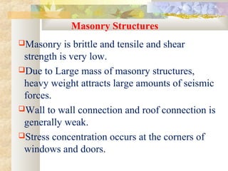
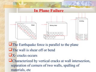
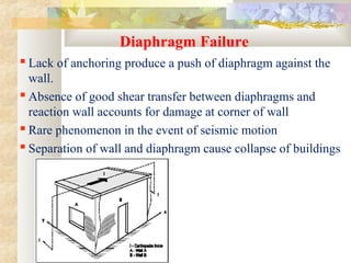
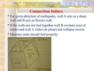
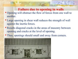
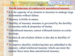
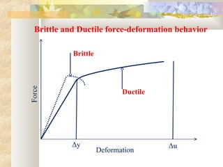
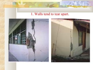
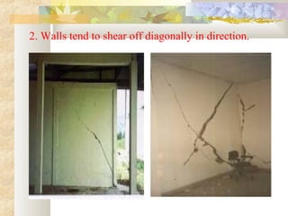
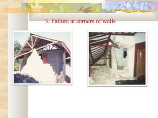
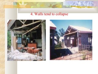
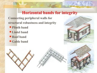
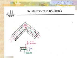
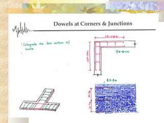
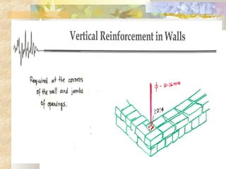
1. Masonry structures are vulnerable to earthquake damage due to their brittle nature and weak connections.
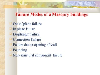
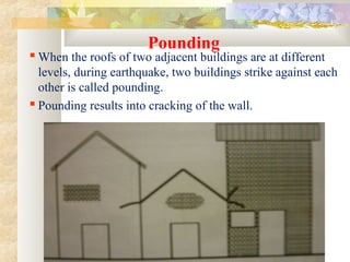
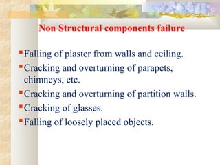
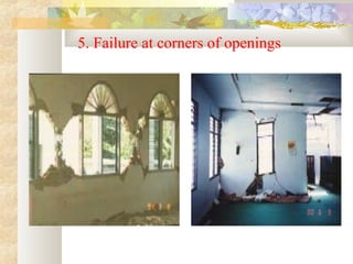
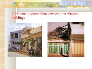
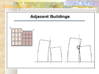
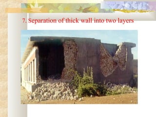
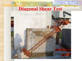
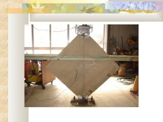
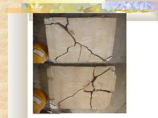
2. Common failure modes of masonry buildings during earthquakes include walls tearing apart, shearing off diagonally, and collapsing at corners.
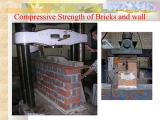
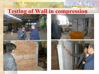
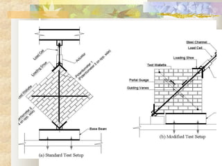
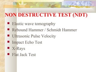
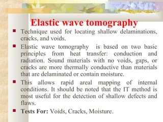
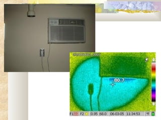
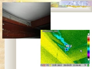
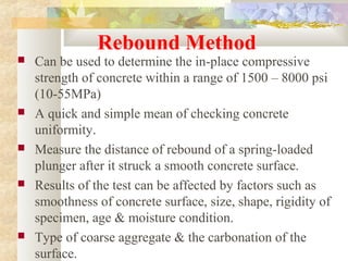
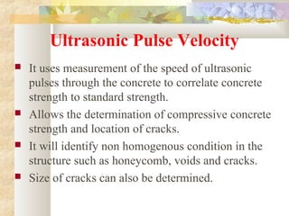
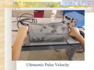
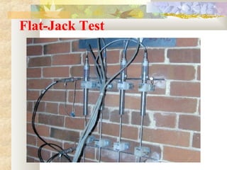
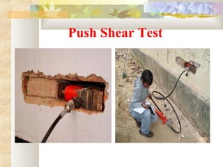
3. Non-destructive testing methods like rebound hammer, ultrasonic pulse velocity, and flat jack tests are used to evaluate the strength of existing masonry structures without damaging them.