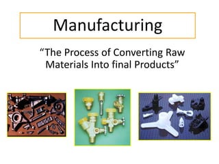
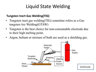
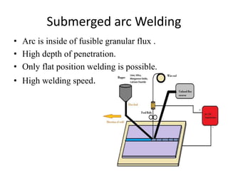
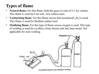
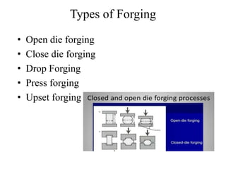
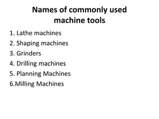
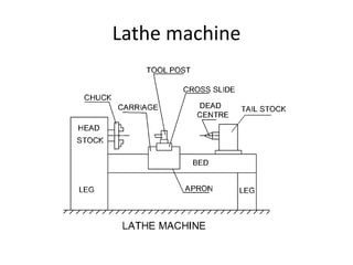
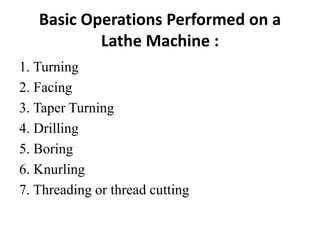
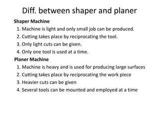
Presentation
on
Manufacturing Process
by
Rajesh kumar
Assistant Professor
Mechanical Department
Manufacturing
“The Process of Converting Raw
Materials Into final Products”
Manufacturing Processes
 Casting
 Joining
 Forming
 Machining
Casting Process
Casting is a manufacturing process by which a molten metal is usually poured
into a mold, which contains a hollow cavity of the desired shape, and then
allowed to solidify. The solidified part is known as a casting, which is ejected or
broken out of the mold to complete the process.
 Casting materials are usually metals.
 Almost all ferrous and non ferrous metal can be cast.
Casting Process
• First a pattern is made.
• Then a cavity is made by placing a pattern in wet sand.
• Next molten metal is poured into the cavity of damp sand.
Basic Features
Pattern: A pattern is made of wood or metal, is a replica of the final
product and is used for preparing mould cavity
Riser: A column of metal placed in the mold to feed the casting as it
shrinks and solidifies. Also known as a "feed head.“
Runner: The channel through which the molten metal is carried from
the sprue to the gate.
Cores: A separated part of the mold, made of sand and generally
baked, which is used to create openings and various shaped cavities in
the casting.
Gate: A channel through which the molten metal enters the casting
cavity.
Continued..
• Parting Line: Joint where mold separates to permit removal of the
pattern and which shows how and where to open the mold.
• Chaplet: A metal support used to hold a core in place in a mold. Not
used when a core print will serve.
• Binders: Materials used to hold molding sand together such as wood
dust.
• Pouring basin: Filling the mold with molten metal.
• Shrinkage: The decrease in volume when molten metal solidifies.
• Mould: The mould contains a cavity whose geometry determines
the shape of cast part.
Categories of Casting Process
Casting process divide onto two broad categories
according to types of mold used:
• Expendable/ Temporary mould casting
• Permanent mould casting
Expandable Mould Casting
Expandable mould means that :
The mold in which the molten metal is solidifies
must be beak or destroyed to remove the casting.
OR
After solidification of molten metal the mold is
break to remove the desired casting. (sand casting)
Expandable mould materials:
The mold are made out of sand, plaster, and similar
materials.
Permanent Mold Casting
In permanent mold casting, the mold is reused many
times.
The molds are commonly made of steel or cast
iron.
Metals commonly cast in the permanent mold
casting include aluminum, magnesium and copper-
based alloys ( brass , bronze).
• Two basic two types of permanent mold casting
1. Die casting
2. Centrifugal casting
Joining process
Any process in which two or more pieces of metal are
joined together by the application of heat, pressure, or
a combination of both.
 It is also called second manufacturing process.
Types of welding
Solid State
Welding
(Autogenous)
Liquid State
Welding
(Homogeneous)
Solid/Liquid
Welding
(Heterogeneous)
Explosive
Welding
Friction
Welding
Forge
Welding
Chemical
Welding
Soldering
Resistance
WeldingArc
Welding
Brazing
TIG MIG SAW PAW
Gas
welding
Thermit
welding
Solid State Welding
 Explosive Welding
• Explosive is used.
• Plastic deformation is used for joining.
• Two plate which are to be welded are maintain at a distance, the movable
plate hit the target and plastic deformation take place.
Liquid State Welding
Tungsten Inert Gas Welding(TIG)
• Tungsten inert gas welding(TIG) sometime refers as a Gas
tungsten Arc Welding(GTAW)
• Tungsten is the best choice for non-consumable electrode due
to their high melting point.
• Argon, helium or mixture of both are used as a shielding gas.
Continued..
Metal Inert Gas Welding(MIG)
• In this technique consumable electrode is used which is in the form of wire.
• Higher penetration as compare to TIG welding.
• Process is complex as compare to TIG welding.
• High initial cost.
Continued..
Submerged arc Welding
• Arc is inside of fusible granular flux .
• High depth of penetration.
• Only flat position welding is possible.
• High welding speed.
Chemical Welding
Thermit Welding
• Thermit is a mixture of aluminium powder and metal oxide.
• Mixture placed in crucible and ignited by means of a fire
cracker.
• Aluminium combines with oxygen and intense heat will be
released
• Temperature generated near about 3000 °C.
Continued..
Oxygen Fuel Gas Welding
OFGW is a group of welding processes which join metals by
heating with a fuel gas flame with or without the application of
pressure and with or without the use of filler metal.
Types of Oxy-fuel Gas Welding
 Oxy-Acetylene or Oxygen- Acetylene Gas Welding
 Oxy-Hydrogen or Oxygen- Hydrogen Gas Welding. It is used
for low melting point materials(replaced by TIG Welding)
Types of flame
• Neutral flame: For this flame, both the gases in ratio of 1:1 by volume.
This flame is used for Cast iron , low carbon steel.
• Carburizing flame: For this flame excess fuel acetylene(C2H2) is used.
This flame is used for Medium carbon steel.
• Oxidizing flame: For this type of flame excess oxygen is used. This type
of welding is used for cu alloys, brass bronze and zinc base metal. Not
applicable for steel welding.
SolidLiquid Welding
Soldering
• The melting point temperature of filler metal is less than 430 °C and it is also less
than melting point temperature of base metal.
• Filler material is an alloy of lead and tin is known as solder.
• Used in electronics industry.
• Flux used in soldering is zinc chloride and Hydrochloric acid
Brazing
• The melting point temperature of filler metal is more than 430 °C and it is also less than
melting point temperature of base metal.
• Filler material is an alloy of Copper and Tin, copper and zinc, copper and silver, copper
and aluminium. This is known as spelter.
• Used in pipe fitting where leak proof joins are requires.
• The flux used in borax and boric acid.
Forming Processes
It is a process in which the desired shape and size are
obtained through plastic deformation of a material.
The stress induced during this process are greater than
the yield strength, but less than the fracture strength of
the material.
Forming can be classified in to three categories:
• Cold working
• Hot working
Cold working
When material is deformed below recrytallization temperature
 Cold working < 0.4Tm
 Tm is melting point of material.
 Minimum or no machining usually required.
Advantage Disadvantage
(a) Better accuracy (a) Higher forces are required
(b)Better Surface finishing (b) Ductility is limited.
(c) Strain hardening increase strength
Hot Working
• Temp. above Recrystallization Temp.
• Holds between (0. 5Tm < T < 0.75Tm)
Advantage
– Lower forces are required
– Fracture can be reduced
– Strength properties are generally isotropic
– No strengthening of the part occurs from work hardening so ductility
improve.
Disadvantage
Lower dimensional accuracy, higher energy, poorer surface finish
Basic Types of Deformation Processes
1. Bulk deformation
– Forging
– Rolling
– Extrusion
– Wire drawing
2. Sheet metalworking
– Bending
– Deep drawing
Types of Forging
• Open die forging
• Close die forging
• Drop Forging
• Press forging
• Upset forging
Extrusion process
Extrusion is a process of Confining(limit) the metal in a
closed cavity and then allowing it to flow from one
opening so that the metal takes place to the shape of
the opening.
Types of extrusion Process
1. Direct extrusion or Forward
2. Indirect Extrusion or Backward
3. Hydrostatics Extrusion
4. Impact Extrusion
Rolling and Wire drawing
Rolling
wire drawing
Ductility is defined when the
material is draw in wire form
Sheet Metalworking
Bending Deep drawing
Machining
• Machining is a process of removing unwanted
material from workpiece.
• Major drawback of this process is loss of
material in the form of chip.
• It is a secondary process.
Names of commonly used
machine tools
1. Lathe machines
2. Shaping machines
3. Grinders
4. Drilling machines
5. Planning Machines
6.Milling Machines
Lathe machine
Basic Operations Performed on a
Lathe Machine :
1. Turning
2. Facing
3. Taper Turning
4. Drilling
5. Boring
6. Knurling
7. Threading or thread cutting
Some Basic Operations Performed
by Lathe machine
Shaping Machines
A shaper is used for producing relatively small
flat surfaces. A single point tool is mounted on
a tool box fitted to a reciprocating ram.
Diff. between shaper and planer
Shaper Machine
1. Machine is light and only small job can be produced.
2. Cutting takes place by reciprocating the tool.
3. Only light cuts can be given.
4. Only one tool is used at a time.
Planer Machine
1. Machine is heavy and is used for producing large surfaces
2. Cutting takes place by reciprocating the work piece
3. Heavier cuts can be given
4. Several tools can be mounted and employed at a time
Drilling Machine
Drilling is an operation through which a drilled
hole is produced in a job. The machine tool
used in this case is called drilling machine and
the cutting tool used is called a drill bit or drill
Operation performed on a drill
machine
• Drilling : Operation of producing a cylindrical hole in a solid body by
means of a drill.
• Reaming : Operation of finishing the drilled hole by means of a
reamer.
• Boring : A drilled hole can be enlarged also by means of boring tool
on the drill machine.
• Counter Boring : Enlarging the diameter of the drilled hole only
upto certain depth. For this counter boring tool is used.
• Counter Sinking : It is enlarging the top end of a drilled hole and
giving it a conical shape by the help of a counter sinking tool.
• Tapping : A tap can be rotated inside an already drilled hole to
produce internal threads.
Grinding
It is the process of removing material by the abrasive action of a
revolving wheel from the surface of a work piece, in order to achieve
required dimension and surface finish of the work piece. The wheel
used for this purpose is called grinding wheel.
Milling is a metal removing process by the help of multi-
tooth(multi edge) revolving cutting tool. The cutting tool
is held on a spindle called arbour and the work piece is
fixed on a table
Milling Machine
ThankYou…….

Manufacturing Processes

  • 1.
  • 2.
    Manufacturing “The Process ofConverting Raw Materials Into final Products”
  • 3.
    Manufacturing Processes  Casting Joining  Forming  Machining
  • 4.
    Casting Process Casting isa manufacturing process by which a molten metal is usually poured into a mold, which contains a hollow cavity of the desired shape, and then allowed to solidify. The solidified part is known as a casting, which is ejected or broken out of the mold to complete the process.  Casting materials are usually metals.  Almost all ferrous and non ferrous metal can be cast.
  • 5.
    Casting Process • Firsta pattern is made. • Then a cavity is made by placing a pattern in wet sand. • Next molten metal is poured into the cavity of damp sand.
  • 6.
    Basic Features Pattern: Apattern is made of wood or metal, is a replica of the final product and is used for preparing mould cavity Riser: A column of metal placed in the mold to feed the casting as it shrinks and solidifies. Also known as a "feed head.“ Runner: The channel through which the molten metal is carried from the sprue to the gate. Cores: A separated part of the mold, made of sand and generally baked, which is used to create openings and various shaped cavities in the casting. Gate: A channel through which the molten metal enters the casting cavity. Continued..
  • 7.
    • Parting Line:Joint where mold separates to permit removal of the pattern and which shows how and where to open the mold. • Chaplet: A metal support used to hold a core in place in a mold. Not used when a core print will serve. • Binders: Materials used to hold molding sand together such as wood dust. • Pouring basin: Filling the mold with molten metal. • Shrinkage: The decrease in volume when molten metal solidifies. • Mould: The mould contains a cavity whose geometry determines the shape of cast part.
  • 8.
    Categories of CastingProcess Casting process divide onto two broad categories according to types of mold used: • Expendable/ Temporary mould casting • Permanent mould casting
  • 9.
    Expandable Mould Casting Expandablemould means that : The mold in which the molten metal is solidifies must be beak or destroyed to remove the casting. OR After solidification of molten metal the mold is break to remove the desired casting. (sand casting) Expandable mould materials: The mold are made out of sand, plaster, and similar materials.
  • 10.
    Permanent Mold Casting Inpermanent mold casting, the mold is reused many times. The molds are commonly made of steel or cast iron. Metals commonly cast in the permanent mold casting include aluminum, magnesium and copper- based alloys ( brass , bronze). • Two basic two types of permanent mold casting 1. Die casting 2. Centrifugal casting
  • 11.
    Joining process Any processin which two or more pieces of metal are joined together by the application of heat, pressure, or a combination of both.  It is also called second manufacturing process.
  • 12.
    Types of welding SolidState Welding (Autogenous) Liquid State Welding (Homogeneous) Solid/Liquid Welding (Heterogeneous) Explosive Welding Friction Welding Forge Welding Chemical Welding Soldering Resistance WeldingArc Welding Brazing TIG MIG SAW PAW Gas welding Thermit welding
  • 13.
    Solid State Welding Explosive Welding • Explosive is used. • Plastic deformation is used for joining. • Two plate which are to be welded are maintain at a distance, the movable plate hit the target and plastic deformation take place.
  • 14.
    Liquid State Welding TungstenInert Gas Welding(TIG) • Tungsten inert gas welding(TIG) sometime refers as a Gas tungsten Arc Welding(GTAW) • Tungsten is the best choice for non-consumable electrode due to their high melting point. • Argon, helium or mixture of both are used as a shielding gas. Continued..
  • 15.
    Metal Inert GasWelding(MIG) • In this technique consumable electrode is used which is in the form of wire. • Higher penetration as compare to TIG welding. • Process is complex as compare to TIG welding. • High initial cost. Continued..
  • 16.
    Submerged arc Welding •Arc is inside of fusible granular flux . • High depth of penetration. • Only flat position welding is possible. • High welding speed.
  • 17.
    Chemical Welding Thermit Welding •Thermit is a mixture of aluminium powder and metal oxide. • Mixture placed in crucible and ignited by means of a fire cracker. • Aluminium combines with oxygen and intense heat will be released • Temperature generated near about 3000 °C. Continued..
  • 18.
    Oxygen Fuel GasWelding OFGW is a group of welding processes which join metals by heating with a fuel gas flame with or without the application of pressure and with or without the use of filler metal. Types of Oxy-fuel Gas Welding  Oxy-Acetylene or Oxygen- Acetylene Gas Welding  Oxy-Hydrogen or Oxygen- Hydrogen Gas Welding. It is used for low melting point materials(replaced by TIG Welding)
  • 19.
    Types of flame •Neutral flame: For this flame, both the gases in ratio of 1:1 by volume. This flame is used for Cast iron , low carbon steel. • Carburizing flame: For this flame excess fuel acetylene(C2H2) is used. This flame is used for Medium carbon steel. • Oxidizing flame: For this type of flame excess oxygen is used. This type of welding is used for cu alloys, brass bronze and zinc base metal. Not applicable for steel welding.
  • 20.
    SolidLiquid Welding Soldering • Themelting point temperature of filler metal is less than 430 °C and it is also less than melting point temperature of base metal. • Filler material is an alloy of lead and tin is known as solder. • Used in electronics industry. • Flux used in soldering is zinc chloride and Hydrochloric acid Brazing • The melting point temperature of filler metal is more than 430 °C and it is also less than melting point temperature of base metal. • Filler material is an alloy of Copper and Tin, copper and zinc, copper and silver, copper and aluminium. This is known as spelter. • Used in pipe fitting where leak proof joins are requires. • The flux used in borax and boric acid.
  • 21.
    Forming Processes It isa process in which the desired shape and size are obtained through plastic deformation of a material. The stress induced during this process are greater than the yield strength, but less than the fracture strength of the material. Forming can be classified in to three categories: • Cold working • Hot working
  • 22.
    Cold working When materialis deformed below recrytallization temperature  Cold working < 0.4Tm  Tm is melting point of material.  Minimum or no machining usually required. Advantage Disadvantage (a) Better accuracy (a) Higher forces are required (b)Better Surface finishing (b) Ductility is limited. (c) Strain hardening increase strength
  • 23.
    Hot Working • Temp.above Recrystallization Temp. • Holds between (0. 5Tm < T < 0.75Tm) Advantage – Lower forces are required – Fracture can be reduced – Strength properties are generally isotropic – No strengthening of the part occurs from work hardening so ductility improve. Disadvantage Lower dimensional accuracy, higher energy, poorer surface finish
  • 24.
    Basic Types ofDeformation Processes 1. Bulk deformation – Forging – Rolling – Extrusion – Wire drawing 2. Sheet metalworking – Bending – Deep drawing
  • 25.
    Types of Forging •Open die forging • Close die forging • Drop Forging • Press forging • Upset forging
  • 26.
    Extrusion process Extrusion isa process of Confining(limit) the metal in a closed cavity and then allowing it to flow from one opening so that the metal takes place to the shape of the opening. Types of extrusion Process 1. Direct extrusion or Forward 2. Indirect Extrusion or Backward 3. Hydrostatics Extrusion 4. Impact Extrusion
  • 27.
    Rolling and Wiredrawing Rolling wire drawing Ductility is defined when the material is draw in wire form
  • 28.
  • 29.
    Machining • Machining isa process of removing unwanted material from workpiece. • Major drawback of this process is loss of material in the form of chip. • It is a secondary process.
  • 30.
    Names of commonlyused machine tools 1. Lathe machines 2. Shaping machines 3. Grinders 4. Drilling machines 5. Planning Machines 6.Milling Machines
  • 31.
  • 32.
    Basic Operations Performedon a Lathe Machine : 1. Turning 2. Facing 3. Taper Turning 4. Drilling 5. Boring 6. Knurling 7. Threading or thread cutting
  • 33.
    Some Basic OperationsPerformed by Lathe machine
  • 34.
    Shaping Machines A shaperis used for producing relatively small flat surfaces. A single point tool is mounted on a tool box fitted to a reciprocating ram.
  • 35.
    Diff. between shaperand planer Shaper Machine 1. Machine is light and only small job can be produced. 2. Cutting takes place by reciprocating the tool. 3. Only light cuts can be given. 4. Only one tool is used at a time. Planer Machine 1. Machine is heavy and is used for producing large surfaces 2. Cutting takes place by reciprocating the work piece 3. Heavier cuts can be given 4. Several tools can be mounted and employed at a time
  • 36.
    Drilling Machine Drilling isan operation through which a drilled hole is produced in a job. The machine tool used in this case is called drilling machine and the cutting tool used is called a drill bit or drill
  • 37.
    Operation performed ona drill machine • Drilling : Operation of producing a cylindrical hole in a solid body by means of a drill. • Reaming : Operation of finishing the drilled hole by means of a reamer. • Boring : A drilled hole can be enlarged also by means of boring tool on the drill machine. • Counter Boring : Enlarging the diameter of the drilled hole only upto certain depth. For this counter boring tool is used. • Counter Sinking : It is enlarging the top end of a drilled hole and giving it a conical shape by the help of a counter sinking tool. • Tapping : A tap can be rotated inside an already drilled hole to produce internal threads.
  • 38.
    Grinding It is theprocess of removing material by the abrasive action of a revolving wheel from the surface of a work piece, in order to achieve required dimension and surface finish of the work piece. The wheel used for this purpose is called grinding wheel. Milling is a metal removing process by the help of multi- tooth(multi edge) revolving cutting tool. The cutting tool is held on a spindle called arbour and the work piece is fixed on a table Milling Machine
  • 39.