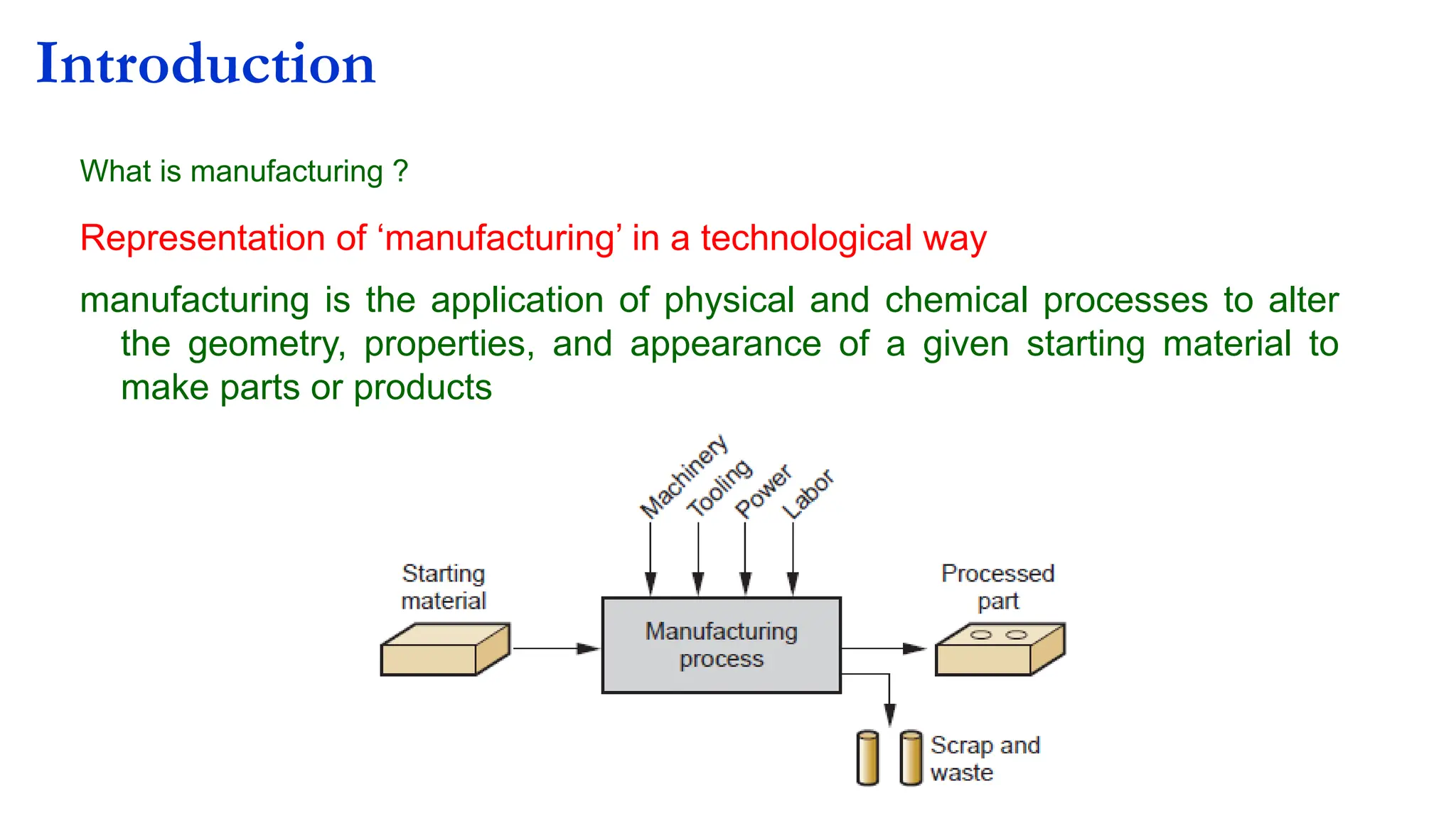
What is manufacturing?
Representation of ‘manufacturing’ in a technological way
manufacturing is the application of physical and chemical processes to alter
the geometry, properties, and appearance of a given starting material to
make parts or products
Introduction
2.
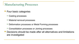
Manufacturing Processes
Fourbasic categories
Casting processes
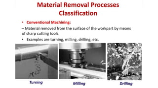
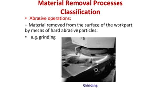
Material removal processes
Deformation processes or Metal Forming processes
Consolidation processes or Joining processes
Decisions should be made after all alternatives and limitations
are investigated
3.
-
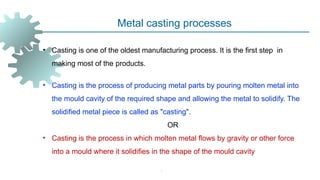
Metal casting processes
•Casting is one of the oldest manufacturing process. It is the first step in
making most of the products.
• Casting is the process of producing metal parts by pouring molten metal into
the mould cavity of the required shape and allowing the metal to solidify. The
solidified metal piece is called as "casting".
OR
• Casting is the process in which molten metal flows by gravity or other force
into a mould where it solidifies in the shape of the mould cavity
4.
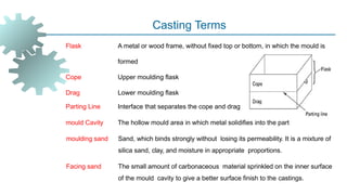
Casting Terms
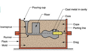
Flask Ametal or wood frame, without fixed top or bottom, in which the mould is
formed
Cope Upper moulding flask
Drag Lower moulding flask
Parting Line Interface that separates the cope and drag
mould Cavity The hollow mould area in which metal solidifies into the part
moulding sand Sand, which binds strongly without losing its permeability. It is a mixture of
silica sand, clay, and moisture in appropriate proportions.
Facing sand The small amount of carbonaceous material sprinkled on the inner surface
of the mould cavity to give a better surface finish to the castings.
6.
-
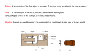
Pattern It isthe replica of the final object to be made. The mould cavity is made with the help of pattern.
Core A separate part of the mould, which is used to create openings and
various shaped cavities in the castings. Generally, made of sand.
Chaplets Chaplets are used to support the cores inside the mould cavity to take care of its own weight.
7.
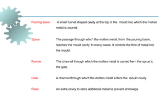
Pouring basin Asmall funnel shaped cavity at the top of the mould into which the molten
metal is poured.
Sprue The passage through which the molten metal, from the pouring basin,
reaches the mould cavity. In many cases it controls the flow of metal into
the mould.
Runner The channel through which the molten metal is carried from the sprue to
the gate.
Gate A channel through which the molten metal enters the mould cavity.
Riser An extra cavity to store additional metal to prevent shrinkage
8.
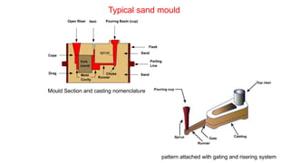
Typical sand mould
MouldSection and casting nomenclature
pattern attached with gating and risering system
-
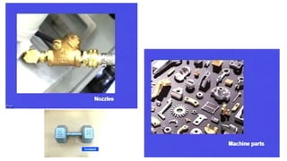
Applications
Big parts
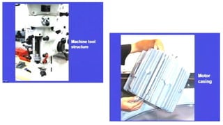
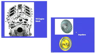
Engine blocks and heads for automotive vehicles, Machine
tool structure, motor casing, impellers, turbine blades,
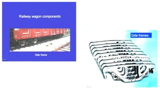
nozzles, pistons, piston rings, wood burning stoves, door
handles, machine frames, railway wheels, water supply
pipes, bells, big statues, and machine parts, Turbine vanes
and aircraft jet engine blades.
Small parts
Dental crowns, jewelry, small statues, frying pans
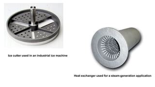
Ice cutter usedin an industrial ice machine
Heat exchanger used for a steam-generation application
16.
-
Advantages of Casting
Molten material can flow into very small sections so that intricate shapes can be made by
this process. As a result, many other operations, such as machining, forging, and
welding, can be minimized.
It is possible to cast practically any material that is ferrous or non-ferrous..
The necessary tools required for casting moulds are very simple and inexpensive.
There are certain parts (like turbine blades) made from metals and alloys that can only be
processed this way. Turbine blades: Fully casting + last machining.
17.
-
Size andweight of the product is not a limitation for the casting process.
Wastage of raw material is less
18.
Disadvantages of Casting
Different disadvantages for different casting processes:
Poor dimensional accuracy and surface finish for some
processes; e.g., sand casting
Safety hazards to workers due to hot molten metals
Metal casting is a labour intensive process
Limitations on mechanical properties
19.
Steps in MakingSand Casting
1. Pattern making
2. Core making
3. moulding
4. Melting and Pouring
5. Cleaning
6. Inspection
The six basic steps in making sand castings are
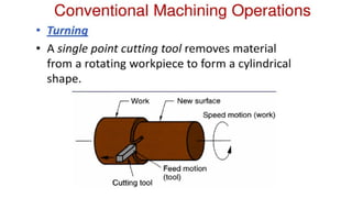
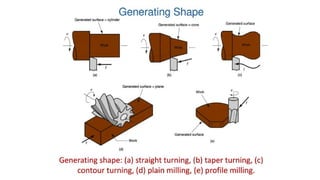
Metal forming processes
Metalforming: Large set of manufacturing processes in which the material is
deformed plastically to take the shape of the die geometry. The tools used for
such deformation are called die, punch etc. depending on the type of process.
Plastic deformation: Stresses beyond yield strength of the workpiece
material is required.
Categories: Bulk metal forming, Sheet metal forming
23.
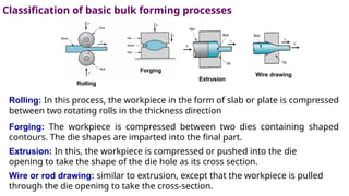
Rolling: In thisprocess, the workpiece in the form of slab or plate is compressed
between two rotating rolls in the thickness direction
Forging: The workpiece is compressed between two dies containing shaped
contours. The die shapes are imparted into the final part.
Extrusion: In this, the workpiece is compressed or pushed into the die
opening to take the shape of the die hole as its cross section.
Wire or rod drawing: similar to extrusion, except that the workpiece is pulled
through the die opening to take the cross-section.
Classification of basic bulk forming processes
Rolling
Forging
Extrusion
Wire drawing
25.
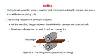
• Rolling isa deformation process in which work thickness is reduced by compressive forces
exerted by two opposing rolls
• The rotating rolls perform two main functions:
• Pull the work into the gap between them by friction between workpart and rolls
• Simultaneously squeeze the work to reduce cross section
Figure 19.1 The rolling process (specifically, flat rolling)
‑
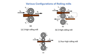
Rolling
(a) 2 highrolling mill
‑
Various Configurations of Rolling mills
(b) 3 high rolling mill
‑
(c) four high rolling mill
‑
28.
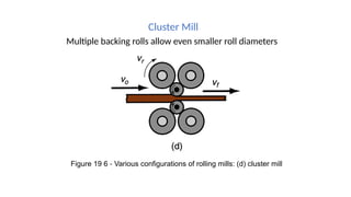
Cluster Mill
Multiple backingrolls allow even smaller roll diameters
Figure 19 6 Various configurations of rolling mills: (d) cluster mill
‑
29.
2. FORGING
• Forgingis term applied to a family of processes where
deformation is induced by localized compressive forces.
• The equipment can be manual or power hammers, presses,
or special forging machines. The term forging usually
implies hot forging done above the recrystaIlization
temperature.
30.
Types of ForgingDies
The distinction is based on the degree to which the flow of work metal s constrained by
the dies
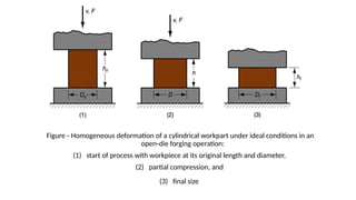
• Open die forging
‑ - work is compressed between two flat (or almost flat) dies, allowing
metal to flow laterally without constraint
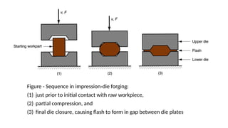
• Impression die forging
‑ - die surfaces contain a cavity or impression that is imparted to
workpart, thus constraining metal flow - flash is created (excess material that is
trimmed off)
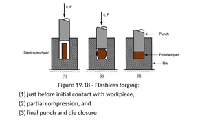
• Flashless forging - workpart is completely constrained in die and no excess flash is
produced
31.
Figure Homogeneous deformationof a cylindrical workpart under ideal conditions in an
‑
open die forging operation:
‑
(1) start of process with workpiece at its original length and diameter,
(2) partial compression, and
(3) final size
32.
Figure Sequence inimpression die forging:
‑ ‑
(1) just prior to initial contact with raw workpiece,
(2) partial compression, and
(3) final die closure, causing flash to form in gap between die plates
33.
Figure 19.18 Flashlessforging:
‑
(1) just before initial contact with workpiece,
(2) partial compression, and
(3) final punch and die closure
35.
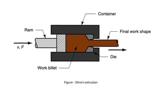
3. Extrusion
Compression formingprocess in which the work metal is forced to flow
through a die opening to produce a desired cross sectional shape
‑
• Process is similar to squeezing toothpaste out of a toothpaste tube
• In general, extrusion is used to produce long parts of uniform cross-sections
• Two basic types of extrusion:
• Direct extrusion
• Indirect extrusion
Comments on DirectExtrusion
• Also called forward extrusion
• As ram approaches die opening, a small portion of billet remains that cannot be
forced through die opening
• This extra portion, called the butt, must be separated from extruded product by
cutting it just beyond the die exit
• Starting billet cross section usually round, but final shape is determined by die
opening
38.
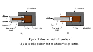
Comments on IndirectExtrusion
• Also called backward extrusion and reverse extrusion
• Limitations of indirect extrusion are imposed by the lower rigidity of
hollow ram and difficulty in supporting extruded product as it exits die
General Advantages ofExtrusion
• Variety of shapes possible, especially in hot extrusion
• Limitation: part cross section must be uniform throughout length
‑
• Grain structure and strength enhanced in cold and warm extrusion
• Close tolerances possible, especially in cold extrusion
• In some operations, little or no waste of material
41.
Definition
• Welding isa materials joining process which produces coalescence of
materials by heating them to suitable temperatures with or without the
application of pressure and with or without the use of filler material.
• Welding is used for making permanent joints.
• It is used in the manufacture of automobile bodies, aircraft frames, railway
wagons, machine frames, structural works, tanks, furniture, boilers, general
repair work and ship building.
42.
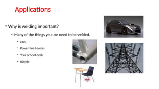
Applications
• Why iswelding important?
• Many of the things you use need to be welded.
• cars
• Power line towers
• Your school desk
• Bicycle
43.
Two Categories ofWelding Processes
Fusion welding - coalescence is accomplished by melting the two parts to be
joined, in some cases adding filler metal to the joint
Examples: arc welding, resistance spot welding, oxyfuel gas welding
Pressure welding - heat and/or pressure are used to achieve coalescence, but
no melting of base metals occurs and no filler metal is added
Examples: forge welding, diffusion welding, friction welding
44.
Advantages of welding
-A good weld is as strong as the base metal
- Low cost of general-welding equipment (economical)
- Portable equipment
- Permits freedom in design
- Lighter, smoother structure
- Both similar & dissimilar metals can be joined
- Simplicity in design, ease of modification/additions
- Mechanization of welding processes
45.
Disadvantages of welding
-Harmful light radiations, fumes, splatter etc.
- Residual stresses & distortion, due to high heat
- Change in metallurgical properties of base metal
- Jigs and fixtures required to hold job
- Edge preparation required
- Skilled labour
- High standards of testing and inspection, etc.
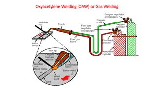
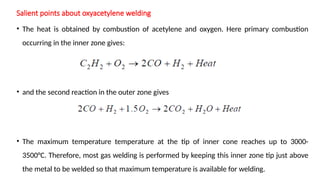
Salient points aboutoxyacetylene welding
• The heat is obtained by combustion of acetylene and oxygen. Here primary combustion
occurring in the inner zone gives:
• and the second reaction in the outer zone gives
• The maximum temperature temperature at the tip of inner cone reaches up to 3000-
3500°C. Therefore, most gas welding is performed by keeping this inner zone tip just above
the metal to be welded so that maximum temperature is available for welding.
48.
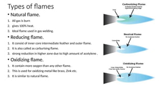
Types of flames
•Natural flame.
1. All gas is burn
2. gives 100% heat.
3. Ideal flame used in gas welding.
• Reducing flame.
1. It consist of inner core intermediate feather and outer flame.
2. It is also called as carburising flame.
3. strong reduction in higher zone due to high amount of acetylene .
• Oxidizing flame.
1. It contain more oxygen than any other flame.
2. This is used for oxidizing metal like brass, Zink etc.
3. It is similar to natural flame.
49.
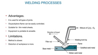
WELDING PROCESSES
• Advantages.
•It is used for all types of joints.
• Oxyacetylene flame can be easily controlled.
• Suitable for thin metal sheets.
• Equipment is portable & versatile.
• Limitations.
• Method is slower.
• Distortion of workpiece is more.
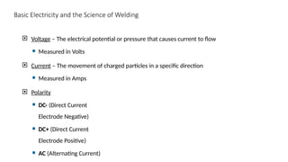
Basic Electricity andthe Science of Welding
Voltage – The electrical potential or pressure that causes current to flow
Measured in Volts
Current – The movement of charged particles in a specific direction
Measured in Amps
Polarity
DC- (Direct Current
Electrode Negative)
DC+ (Direct Current
Electrode Positive)
AC (Alternating Current)
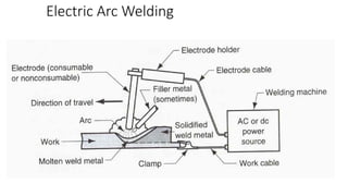
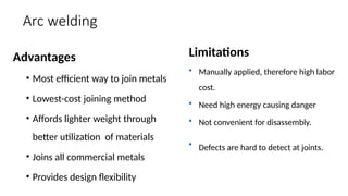
Arc welding
Advantages
• Mostefficient way to join metals
• Lowest-cost joining method
• Affords lighter weight through
better utilization of materials
• Joins all commercial metals
• Provides design flexibility
Limitations
• Manually applied, therefore high labor
cost.
• Need high energy causing danger
• Not convenient for disassembly.
• Defects are hard to detect at joints.
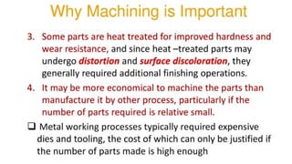
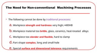
The Need forNon-conventional Machining Processes
The following cannot be done by traditional processes:
a. Workpiece strength and hardness very high,>400HB
b.Workpiece material too brittle, glass, ceramics, heat-treated alloys
c. Workpiece too slender and flexible, hard to clamp
d.Part shape complex, long and small hole
e. Special surface and dimensional tolerance requirements
79.
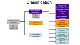
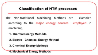
Classification of NTMprocesses
The Non-traditional Machining Methods are classified
according to the major energy sources employed in
machining.
1. Thermal Energy Methods
2. Electro - Chemical Energy Method
3. Chemical Energy Methods
4. Mechanical Energy Methods
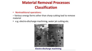
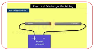
Electrical Discharge Machining
It is also known as Spark over-initiated discharge machining, Spark
erosion machining or simply Spark machining.
It is probably the most versatile of all the electrical machining methods.
Mechanics of material removal - melting and evaporation aided by
cavitations.
This process may be used for machining any material, irrespective of its
hardness, which is an electrical conductor.
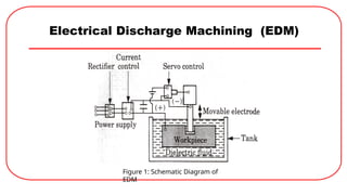
EDM Set-up
The mainelements of this setup include
1. Power supply source
2. Dielectric medium
3. Workpiece and tool
4. Servo control
5. Speed reduction gear box
6. A rack and pinion or some other suitable
mechanism for tool feed
7. An electric circuit to generate discharge, etc.
85.
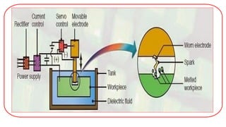
EDM Set-up (Contd.)
Both, the tool and the work piece are connected to the
D. C.
Electric supply source.
The workpiece is connected to the positive terminal
The tool to the negative terminal of the power source.
Consequently, the work piece becomes Anode and the
tool
Cathode.
87.
EDM Working
Theworkpiece and the electrode (tool) are separated by a gap,
called
Spark gap, ranges from 0.005 mm to 0.05 mm.
This gap is filled up by the dielectric, which breaks down when a
proper voltage is applied between these two.
A circuit voltage of 50 V to 450 V is applied, electrons start flowing
from the cathode, due to the electrostatic field, and the gap is
ionized.
The consequent drop in resistance and discharge of electric
energy results in an electrical breakdown.
The electric spark so caused directly impinges on the surface of
the workpiece.
It takes only a few micro seconds to complete the cycle and the
spark
resulting in the development of a very high
temperature
discharges hit the workpiece with considerable force and
velocity,
(around
10,000°C) on the spot hit by the
discharges.
88.
EDM Working
Thisforces the metal to melt, and a portion of it may be vaporized
even.
These vaporized or melted particles of the metal are thrown into
the gap by the electrostatic and electromagnetic forces, from where
they are driven away by the flowing liquid dielectric.
It should be remembered that erosion takes place on both, the tool as
well as the workpiece, but the former is eroded much less as
compared to the latter.
It is because the tool tip is subjected to compressive forces due to the
electric and magnetic fields, resulting in a slower erosion of the
metal from its surface.
The rate of metal removal depends upon the discharge current,
duration
of pulse and the rate of pulse repetition.
89.
Tool Electrode
Prime requirementsEDM tool Material
1. It should be electrically conductive.
2. It should have good machinability,thus allowing
easy
manufacture of complex shapes.
3. It should have low erosion rate or good work to
tool wear ratio.
4. It should have low electrical resistance.
5. It should have high melting point.
6. It should have high electron emission.
90.
EDM Tool
The usualchoices for tool (electrode) materials are
• Copper,
• brass,
• alloys of zinc and tin,
• hardened plain carbon steel,
• copper tungsten,
• silver tungsten,
• tungsten carbide,
• copper graphite, and graphite.
91.
Advantages
1. Hardness, toughnessor brittleness of the material poses no problems.
Due to this EDM can be used for machining materials that are too
hard or brittle to be machined by conventional methods.
2. The method does not leave any chips or burrs on the work
piece.
3. Cutting forces are virtuallyzero, so very delicate and fine work can
be done.
4. The process dimension repeatability and surface finish
obtained in finishing are extremely good.
5. The characteristicsurface obtained,which is made up of craters,
helps in better oil retention. This improves die life.
92.
Disadvantages
1. Only electricallyconductive materials can be machined by EDM. Thus
non - metallic, such as plastics, ceramics or glass, cannot be machined
by EDM.
2. Electrode wear and over-cut are serious problems.
3. A re-hardened, highly stressed zone is produced on the work surface by
the heat generated during machining. This brittle layer can cause
serious problems when the part is put into service.
4. Perfectly square corners cannot be made by EDM.
5. High specific energy consumption (about 50 times that in conventional
machining)
6. MRR is quite low
93.
Applications
The EDM processoffers the following main Applications:
1. This process is very useful in tool manufacturing due to the ease
with which hard materials and alloys can be machined.
2. Re-sharpening of cutting tools.
3. Manufacturing of die
98.
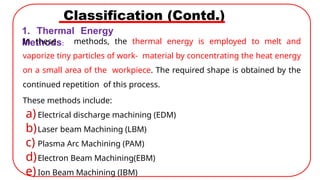
Classification (Contd.)
1. ThermalEnergy
Methods:
In these methods, the thermal energy is employed to melt and
vaporize tiny particles of work- material by concentrating the heat energy
on a small area of the workpiece. The required shape is obtained by the
continued repetition of this process.
These methods include:
a)Electrical discharge machining (EDM)
b)Laser beam Machining (LBM)
c) Plasma Arc Machining (PAM)
d)Electron Beam Machining(EBM)
e)Ion Beam Machining (IBM)
99.
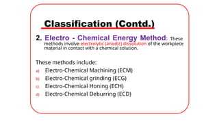
Classification (Contd.)
2. Electro- Chemical Energy Method: These
methods involve electrolytic (anodic) dissolution of the workpiece
material in contact with a chemical solution.
These methods include:
a) Electro-Chemical Machining (ECM)
b) Electro-Chemical grinding (ECG)
c) Electro-Chemical Honing (ECH)
d) Electro-Chemical Deburring (ECD)
100.
Classification (Contd.)
3. ChemicalEnergy Methods: These methods
involve controlled etching of the workpiece material
in contact with a chemical solution.
1. Chemical Machining Method (CHM).
101.
Classification (Contd.)
4. MechanicalEnergy Methods: In these
methods, the material is principally removed by
mechanical erosion of the workpiece material.
These methods include:
a) Ultra Sonic Machining (USM)
b) Abrasive Jet Machining (AJM)
c) Water Jet Machining (WJM)