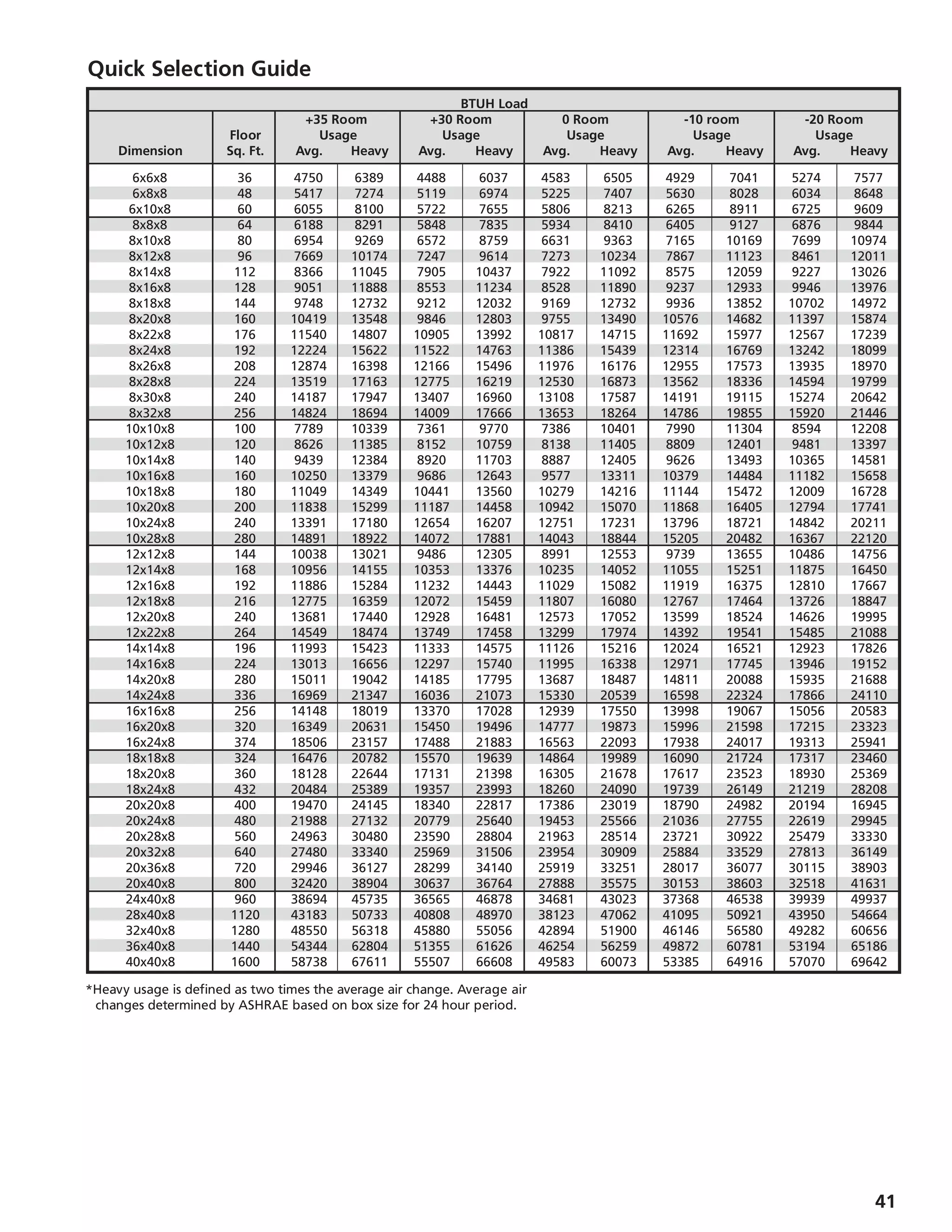
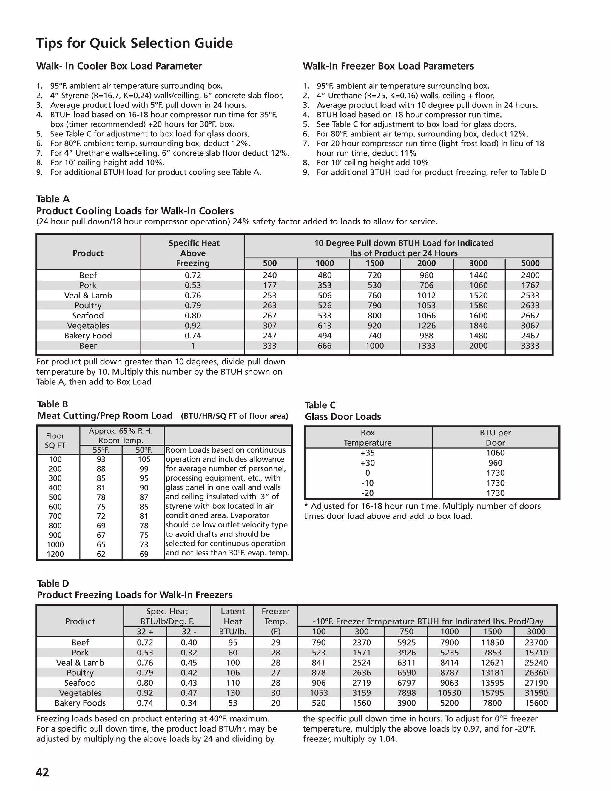
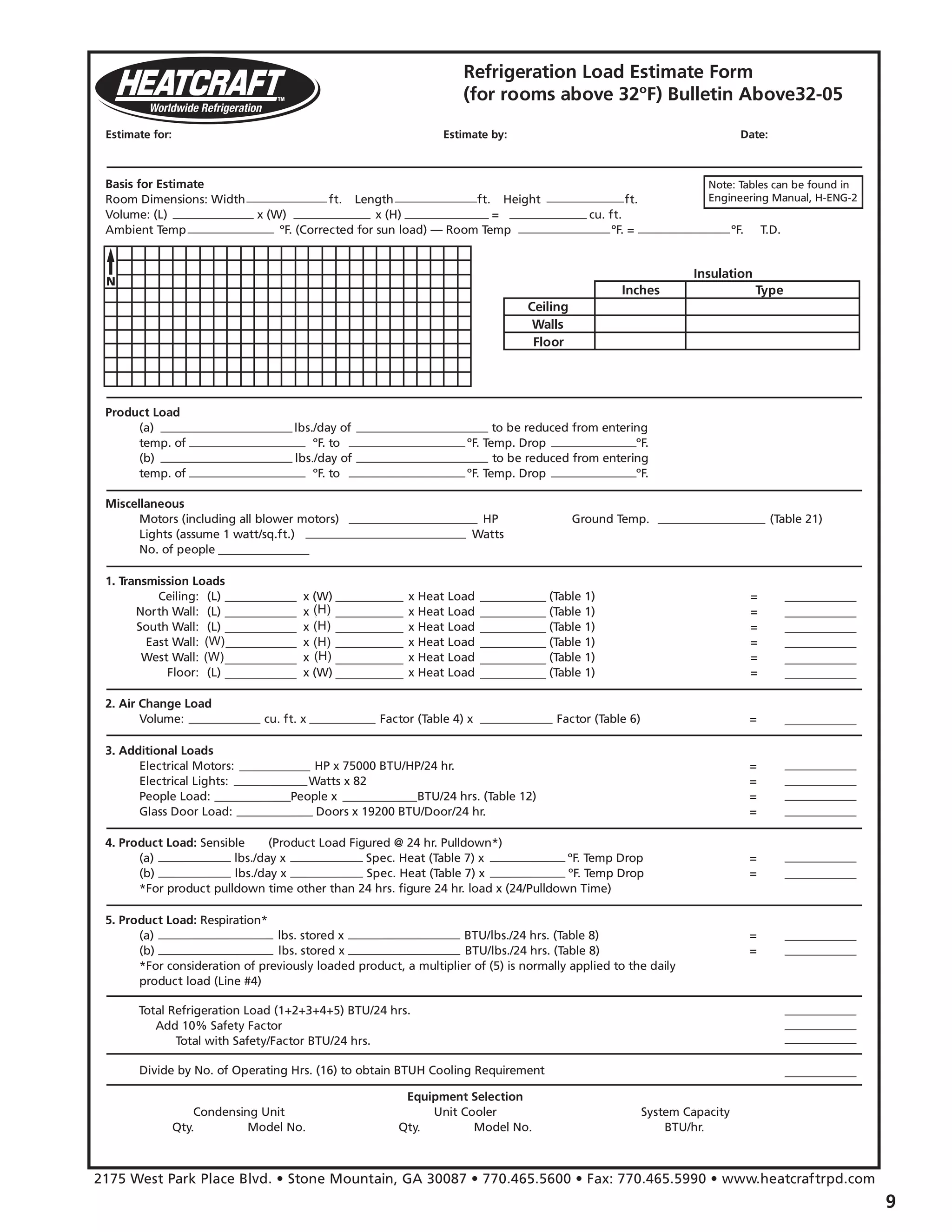
This document provides guidance on calculating refrigeration loads for commercial refrigeration systems. It outlines the key factors to consider in an initial job survey, including design temperatures, storage requirements, dimensions, insulation, infiltration, and product details. It then describes the main sources of heat gain to calculate: transmission load through walls/floors, air changes, miscellaneous loads, and product load. Tables and examples are provided to simplify calculating each load. Quick selection charts and calculators are also included to estimate loads for small/medium and large coolers and freezers when full calculations are not possible.

![[ (4.88) ( door height) (area/2) (minutes open) ( temp. diff. ºF.)
(enthalpy incoming air – enthaply warehouse air) ] [ (1–X)]
Specific Volume of Incoming Air
Where X = % of heat transmission blocked by thermal barrier.
For freezers it becomes necessary to provide heat in the base slab
to avoid freezing of the ground water and heaving of the floor.
Minimum slab temperature should be at least 40ºF. Normally, 55ºF.
should be used for freezer applications.
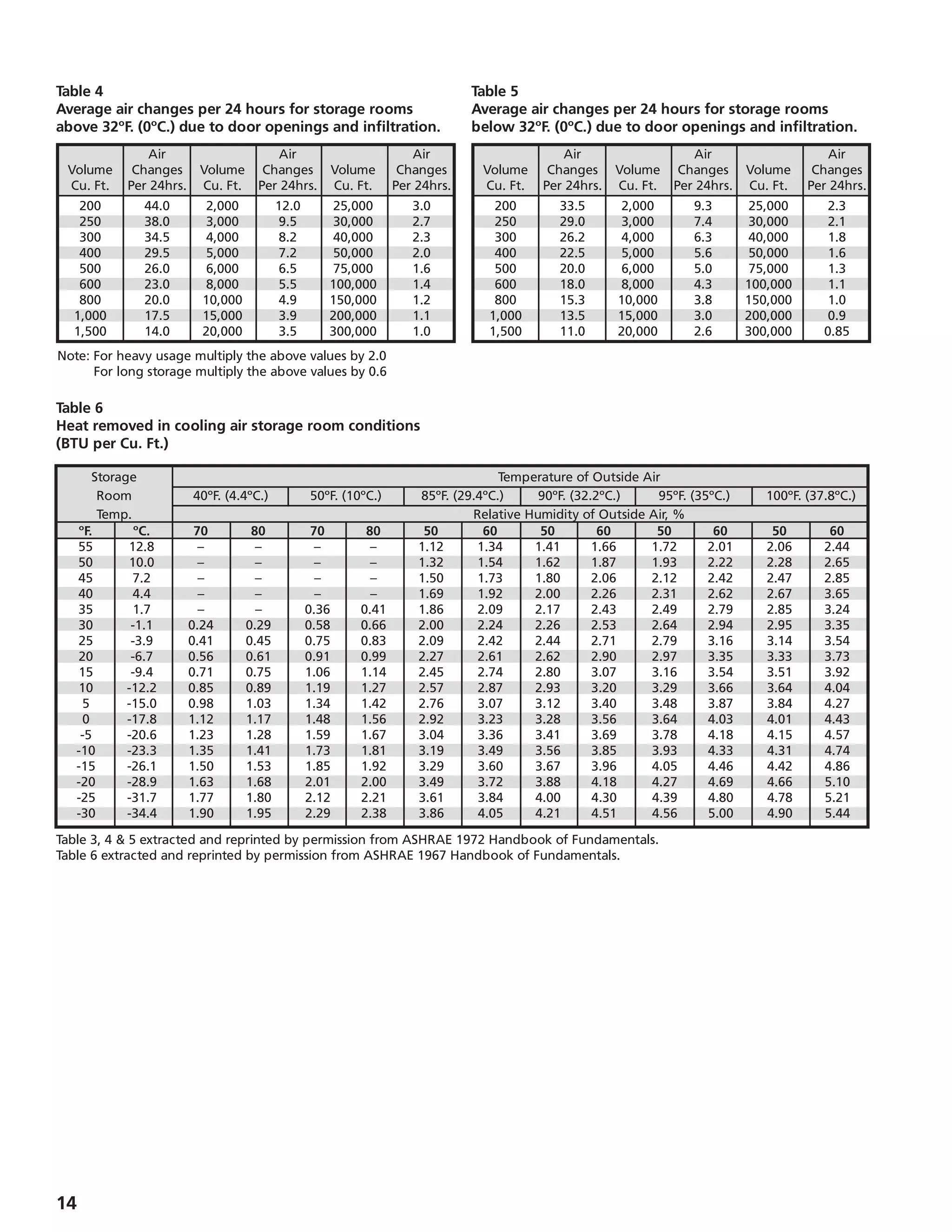
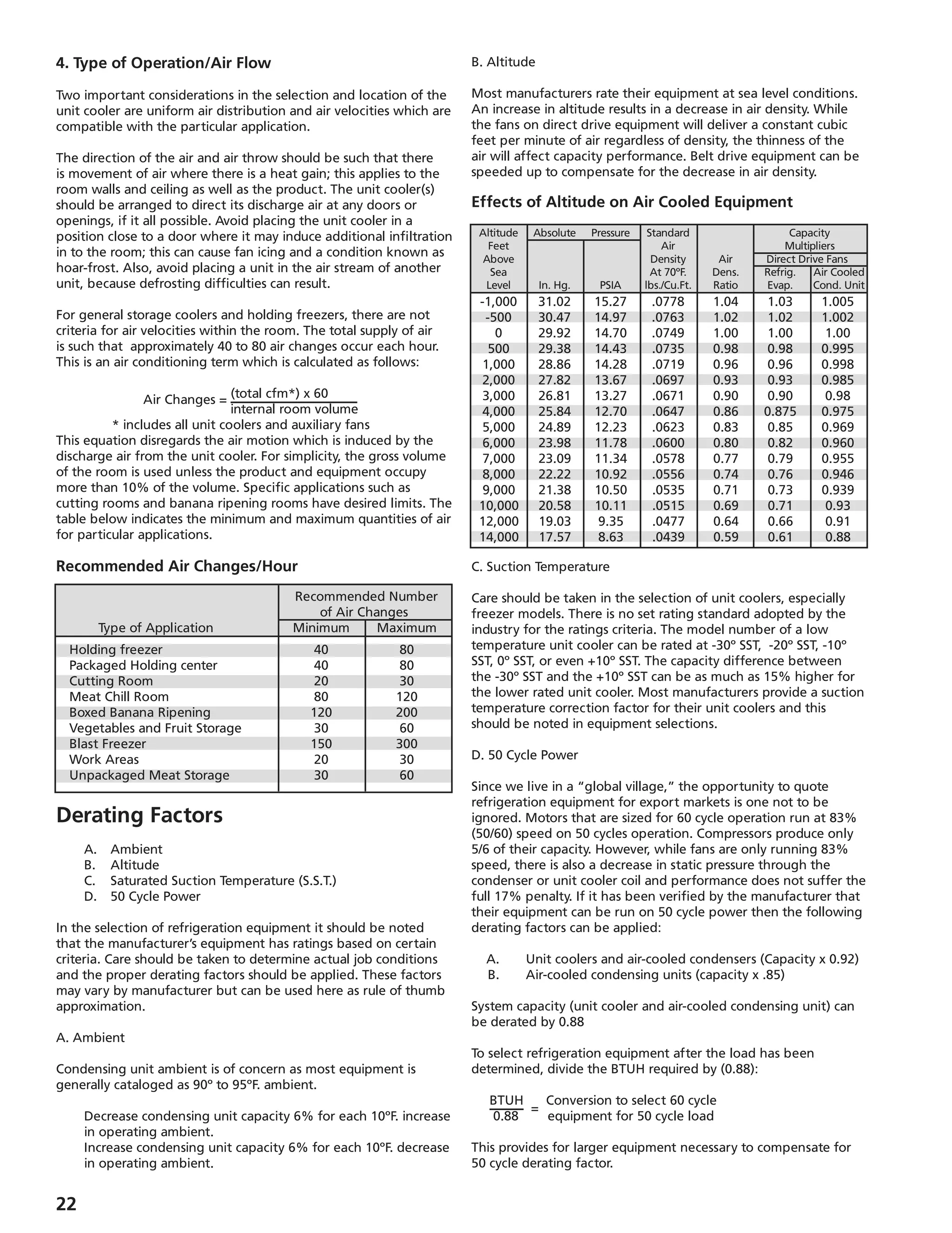
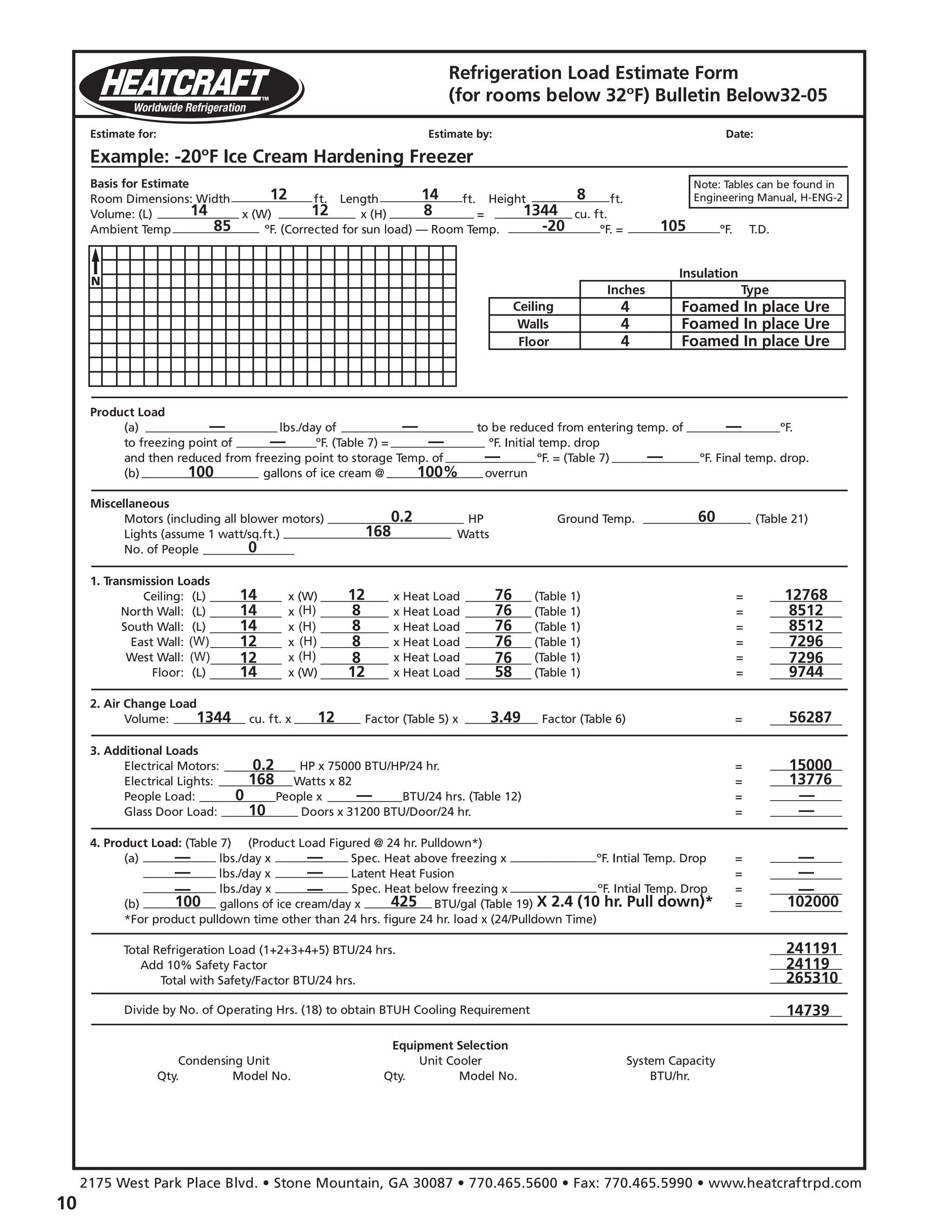
2. Air Change Load
(a) Average Air Change- when the door to a refrigerated room is
opened, warm outside air will enter the room. This air must be
cooled to the refrigerated room temperature, resulting in an
appreciable source of heat gain. This load is sometimes called
the infiltration load. The probable number of air changes per
day and the heat that must be removed from each cubic foot
of the infiltrated air, are given in tables based on experience
(see Table 4, 5 6, page 14). For heavy usage, the infiltration
may be doubled or more.
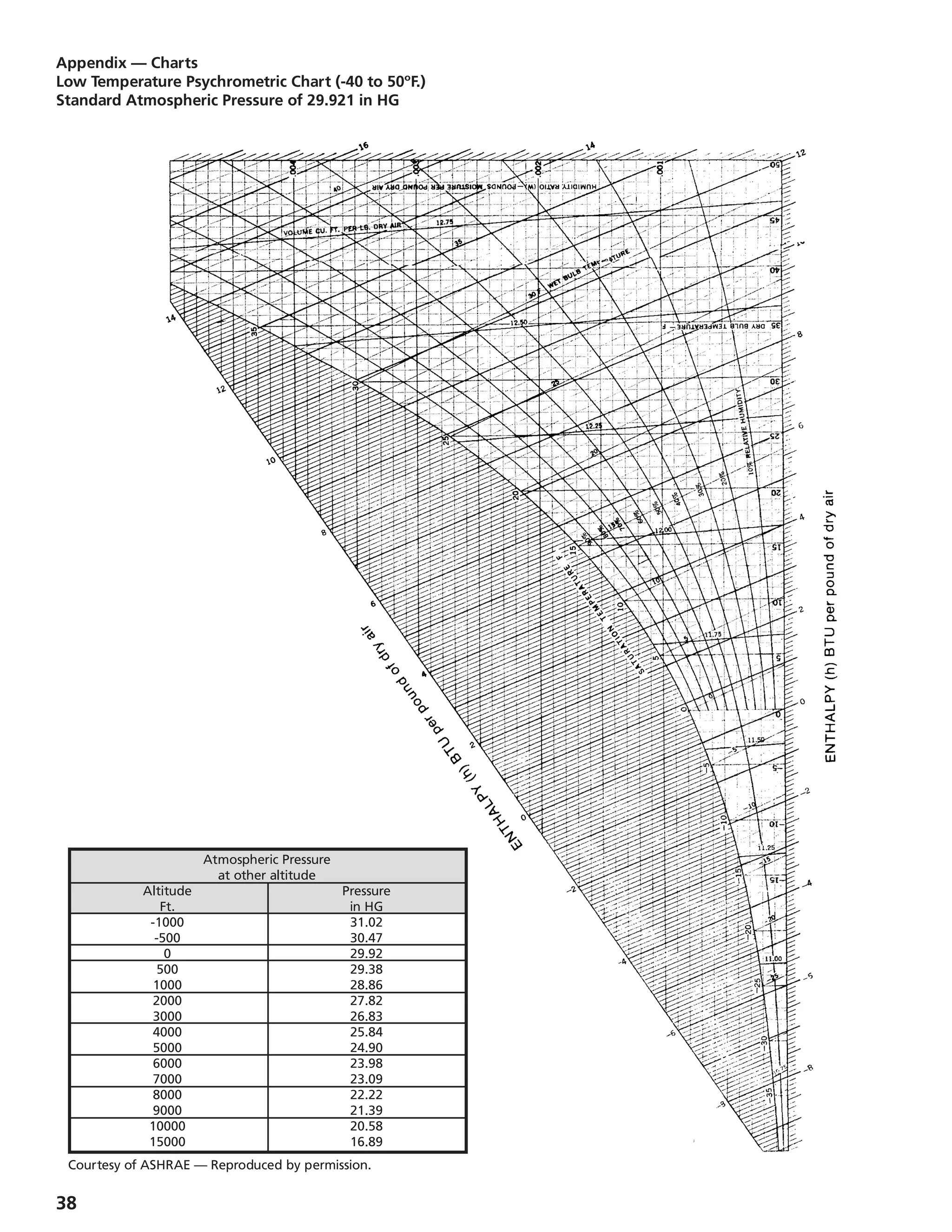
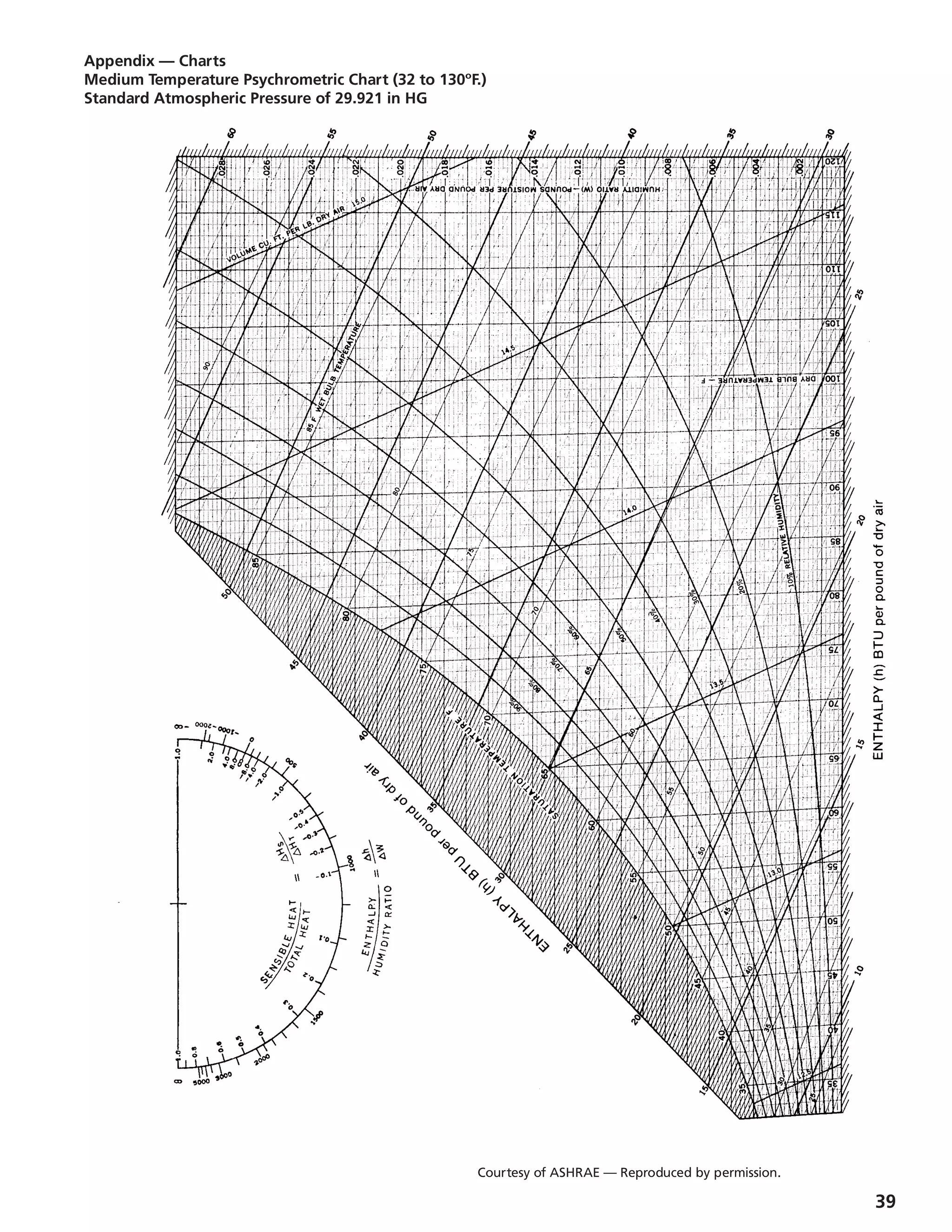
(b) Infiltration Through a Fixed Opening- As an alternate to the
average air change method using the Psychrometric Chart
(page 37), the following formulas may be used to calculate
the infiltration resulting from natural ventilation (no wind)
through external door openings.
The air change load can be substantial and every means
should be taken to reduce the amount of infiltration entering
the box. Some effective means of minimizing this load are:
• Automatic closing refrigerator doors
• Vestibules or refrigerated anterooms
• Plastic strip curtains
• Air Curtains
• Inflated bumpers on outside loading doors.
3. Miscellaneous Loads
Although most of the heat load in a refrigerated room
or freezer is caused by wall heat leakage, air changes and
product cooling or freezing, there are three other heat
sources that should not be overlooked prior to the selection
of the refrigeration equipment. Since the equipment has to
maintain temperature under design conditions, these loads are
generally averaged to a 24 hour period to provide for capacity
during these times.
(a) Lights- typically storage requirements are 1 to 1-1/2 watt per
square foot. Cutting or processing rooms can be double the
wattage. Each watt is multiplied by 3.42 BTU/watt to obtain a
BTUH figure. This is then multiplied by 24 to obtain a
daily figure.
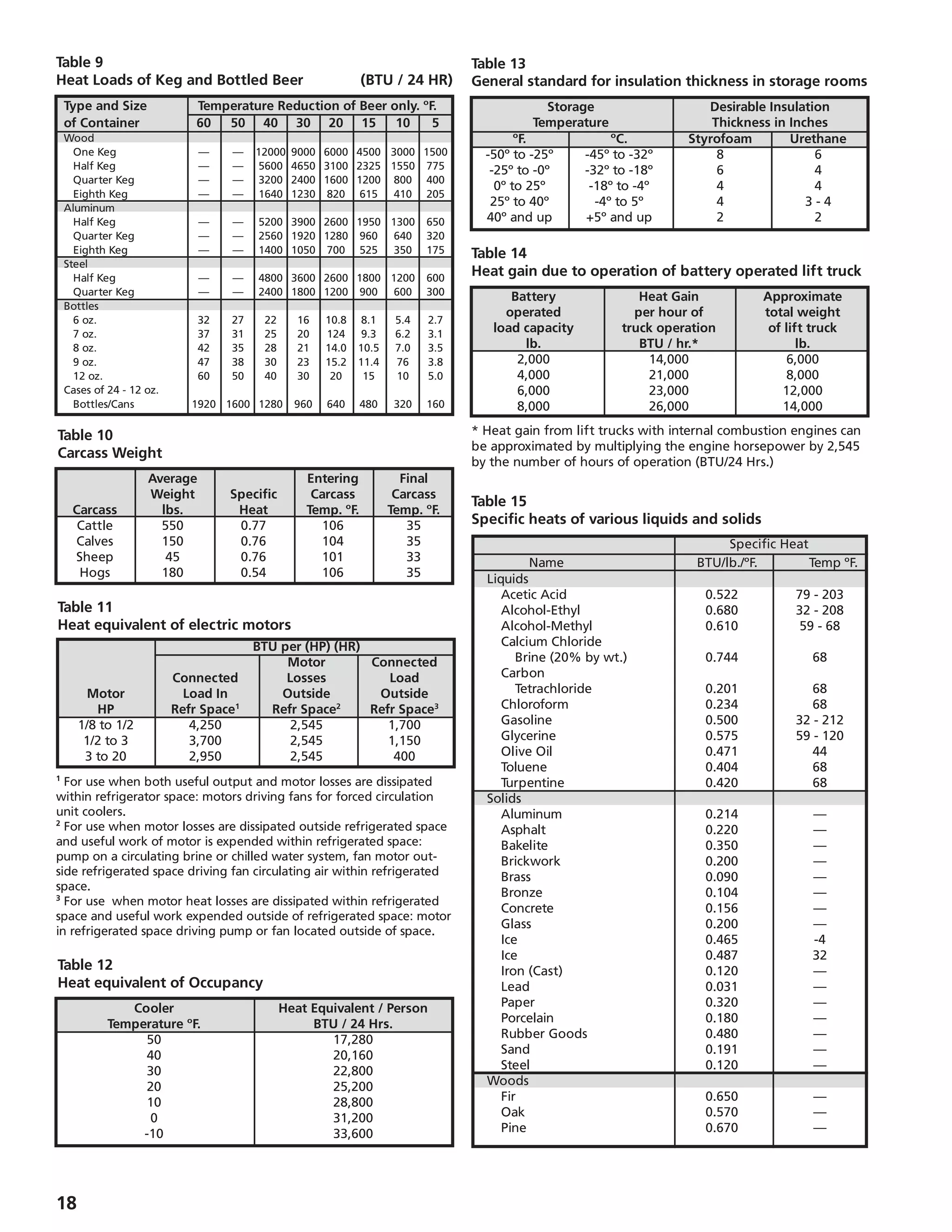
(b) Motors- smaller motors are usually less efficient and tend to
generate more heat per horsepower as compared to larger
motors. For this reason Table 11, on page 18, is broken down
in to H.P. groups. Also, motors inside the refrigerated area will
reject all of their heat losses as shown in Table 11. However,
motors that are located outside but do the work inside, like
a conveyor, will reject less heat into the refrigerated space. If
powered material handling equipment is used, such as forklift
trucks, this must be included under Motor Heat Loads.
Generally only battery operated lift trucks are used in
refrigerated rooms, which represent a heat gain of 8,000 to
15,000 BTU/hr. or more over the period of operation. If motor
or loading conditions are not known, then calculate one
motor horsepower for each 16,000 cubic foot box in a storage
cooler and one HP for each 12,500 C.F. in a storage freezer
which allows for fan motors and some forklift operations.
These figures can be higher in a heavily used area, i.e. loading
dock or distribution warehouse.
(c) Occupancy- People working in the refrigerated storage area
dissipate heat at a rate depending on the room temperature
(Table 12, page 18). Multiple occupancies for short periods
should be averaged over a 24 hour period. If occupancy load
is not known, allow one person per 24 hour for each 25,000
cubic foot space.
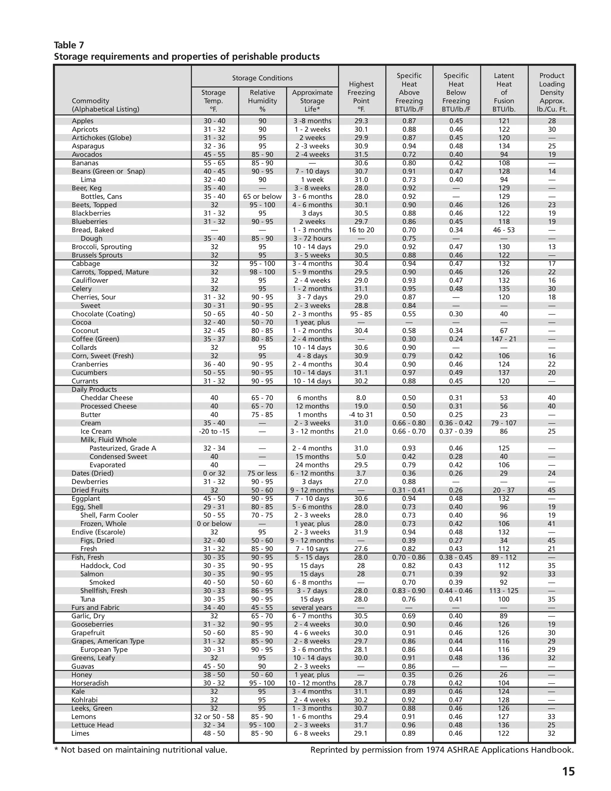
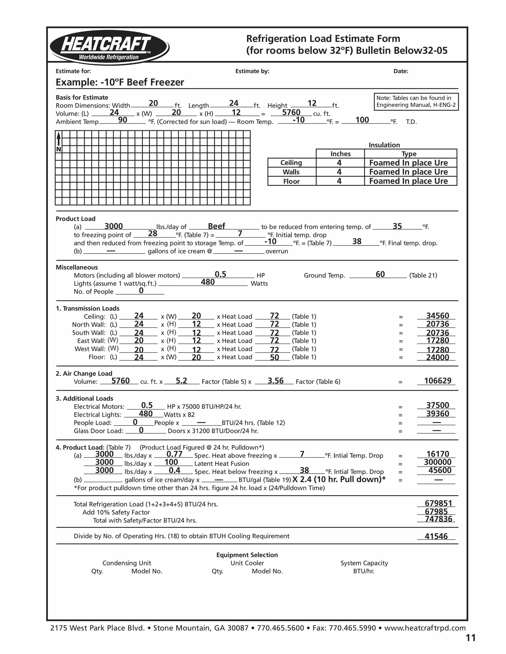
4. Product Load
Whenever a product having a higher temperature is placed
in a refrigerator or freezer room, the product will lose its
heat until it reaches the storage temperature. This heat load
consists of three separate components: (see Table 7, page 15-
16).
(a) Specific Heat- The amount of heat that must be removed
from one pound of product to reduce the temperature of this
pound by 1ºF., is called its specific heat. It has two values: one
applies when the product is above freezing; the second is
applicable after the product has reached its freezing point.
(b) Latent Heat- The amount of heat that must be removed from
one pound of product to freeze this pound is called the latent
heat of fusion.
Most products have a freezing point in the range of 26ºF. to
31ºF. If the exact temperature is unknown, it may be
assumed to be 28ºF.
There is a definite relationship between the latent heat of
fusion and the water content of the product and its specific
and latent heats.
Estimating specific and latent heats:
Sp. Ht. above freezing = 0.20 + (0.008 X % water)
Sp. Ht. below freezing = 0.20 + (0.008 X % water)
Latent Heat = 143.3 X % water
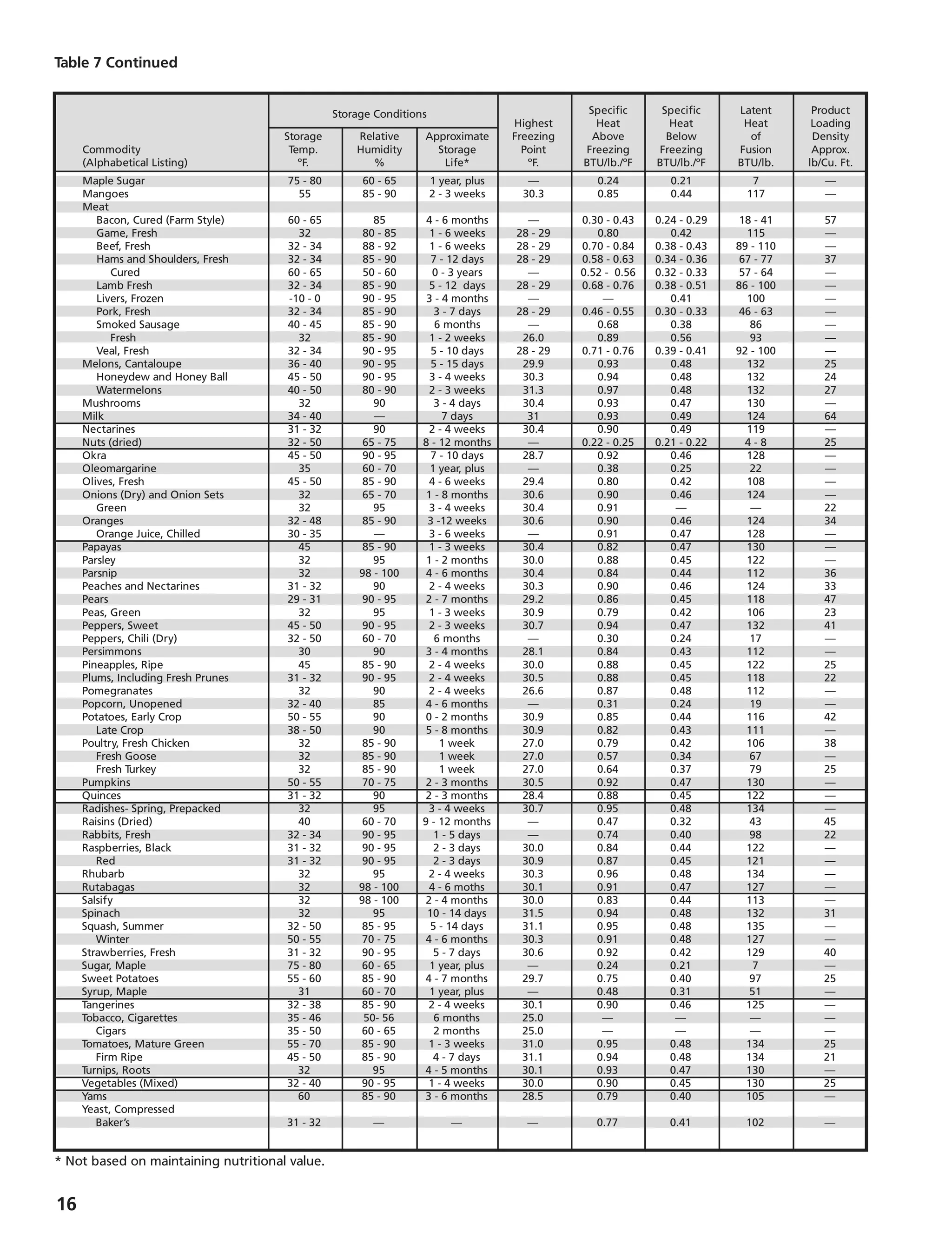
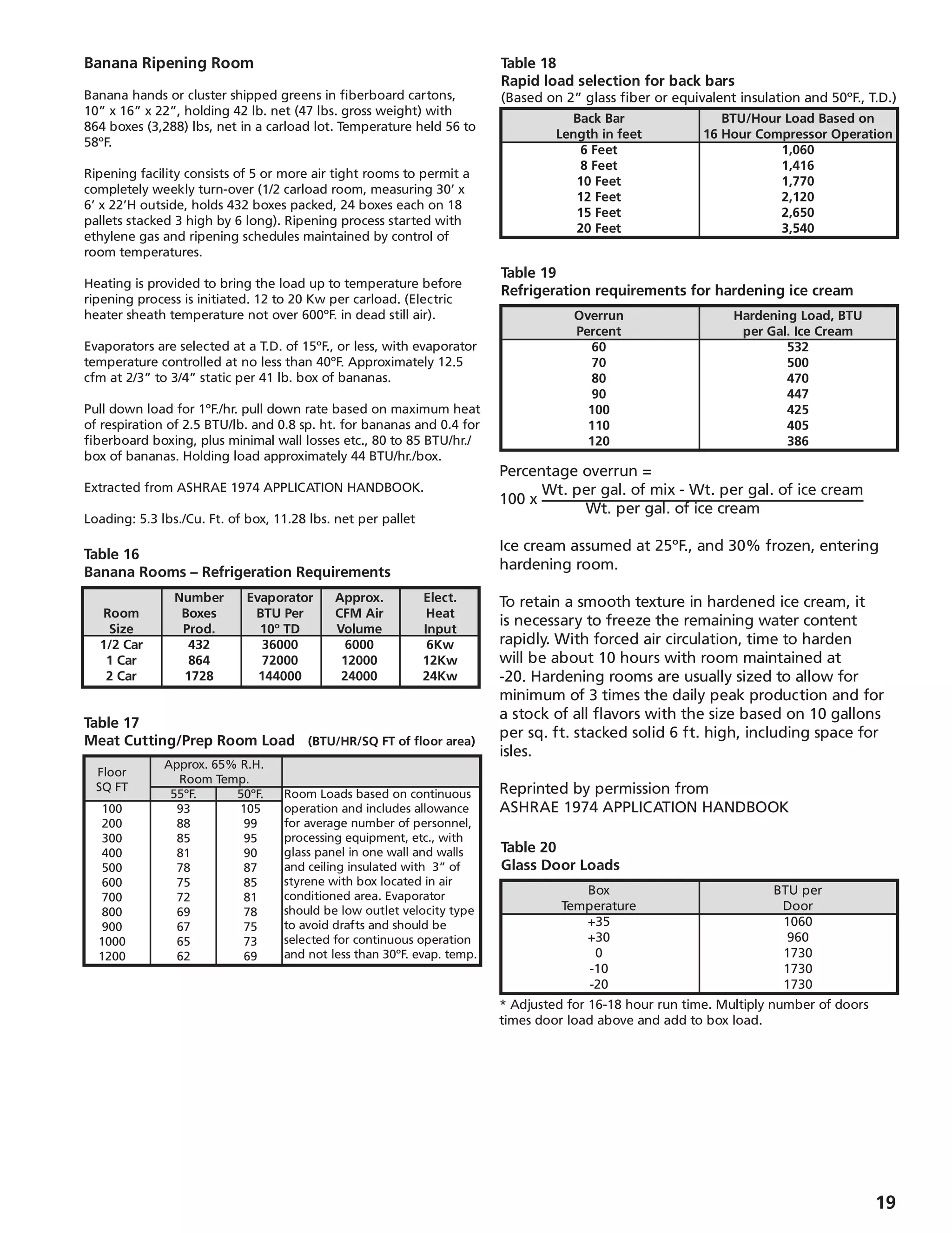
(c) Respiration- Fresh fruits and vegetables are alive. Even in
refrigerated storage they generate heat which is called the
heat of respiration. They continually undergo a change in
which energy is released in the form of heat, which varies with
the type and temperature of the product. Tabulated values are
usually in BTU/lb./24 hours (Table 8, page 17), and are applied
to the total weight of product being stored and not just the
daily turnover.
(d) Pull down Time- When a product load is to be calculated at
other than a 24 hour pull down, a correction factor must be
multiplied to the product load.
24 hours
Pull down Time
Note: While product pull down can be calculated, no
guarantee should be made regarding final product
temperature due to many uncontrollable factors (i.e., type of
packaging, position in the box, method of stacking, etc.)
5. Safety Factor
When all four of the main sources of heat are calculated,
a safety factor of 10% is normally added to the total
refrigeration load to allow for minor omissions and
inaccuracies (additional safety or reserve may be available
from the compressor running time and average loading).](https://image.slidesharecdn.com/manualdeingenierabohn-150708144513-lva1-app6891/75/Manual-de-ingenieria-bohn-5-2048.jpg)
![13
Insulation Insul. K Factor 6” 8” 10” 12”
Air 4.65 6.94 6.65 6.50 6.40
Vermiculite .47 2.73 2.67 2.64 2.62
Sawdust .45 2.70 2.65 2.62 2.60
Cork .38 2.62 2.57 2.55 2.53
Rock Wool .30 2.52 2.49 2.47 2.45
Mac. Paper .28 2.50 2.46 2.45 2.43
Styrofoam .24 2.45 2.42 2.40 2.40
Polyurethane .16 2.36 2.33 2.33 2.32
Type of East South West Flat
Surface Wall Wall Wall Roof
Dark Colored Surfaces,
Such as:
Slate Roofing 8 5 8 20
Tar Roofing
Black Paints
Light Colored Surface,
Such as:
White Stone 4 2 4 9
Light Colored Cement
White Paint
Medium Colored Surface,
Such as:
Unpainted Wood
Brick 6 4 6 15
Red Tile
Dark Cement
Red, Gray or Green Paint
1 4 5.10 204 230 255 281 306 332 357 383 408 434 459 485 510 536 561 587 612
2 8 3.40 136 153 170 187 204 221 238 255 272 289 306 323 340 357 374 391 408
4 3 2 12.6 1.80 72 81 90 99 108 117 126 135 144 153 162 171 180 189 198 207 216
5 4 2 16.4 1.44 58 65 72 79 87 94 101 108 115 122 130 137 144 151 159 166 173
6 5 3 19.6 1.20 48 54 60 66 72 78 84 90 96 102 108 114 120 126 132 138 144
8 6 4 3 25 0.90 36 41 45 50 54 59 63 68 72 77 81 86 90 95 99 104 108
10 8 4 33 0.72 29 32 36 40 43 47 50 54 58 61 65 68 72 76 79 83 86
10 6 38.7 0.60 24 27 30 33 36 39 42 45 48 51 54 57 60 63 66 69 72
6 50 0.48 19 22 24 26 29 31 34 36 38 41 43 46 48 51 53 55 58
Single window glass . 9 27 1080 1215 1350 1490 1620 1760 1890 2030 2160 2290 2440 2560 2700 2840 2970 3100 3240
Double Window Glass 2.2 11 440 495 550 610 660 715 770 825 880 936 990 1050 1100 1160 1210 1270 1320
Triple Window Glass 3.4 7 280 315 350 390 420 454 490 525 560 595 630 665 700 740 770 810 840
6” Concrete Floor 4.8 5 200 225 250 275 300 325 350 375 400 425 450 475 500 525 550 575 600
Insulation (Inches) Heat Load (BTU Per 24 Hours Per One Square Foot of Outside Surface)
Cork Glass Urethane
or Fiber or Urethane (Foamed Temperature Reduction in ºF.
Mineral Poly- (Sprayed) in R (Outside Air Temperature Minus Room Temperature)
Wool Styrene Place)
k = .30 k = .26 k = .16 k = .12 1 40 45 50 55 60 65 70 75 80 85 90 95 100 105 110 115 120
Appendix - Tables
Note: Above insulation “K” Factors [Thermal Conductivity, BTU
per (hour) (square foot) (ºF. per inch of thickness)] and heat
gain factors for Cork and Window Glasses are extracted and
Insulation Values
“K” Factor - Insulating Value of any material is rated by its thermal conductivity
“U” Factor - Overall coefficient of heat transfer, BTU per hour/per square foot/per degree F.
“R” Factor - Thermal resistances
“X” = Inches of Insulation
K = UX = X/R
U = K/X = 1/R
R = 1/U = X/K
Table 2
Effective K Factor in Block Thickness of Insulation
Note: If blocks have 3 holes, add .75 to all of the values shown. The
above data is being shown for reference purpose only - this is a very
inefficient method of construction/insulation due to:
1. Concrete webs are dominant factor in calculating insulating effect.
2. Filling techniques may leave blocks improperly filled.
3. No vapor seal present - moisture infiltration decreases insulation
effect.
4. If used for freezers, moisture will freeze inside block and break
out the surface of the block.
5. Blocks are highly subject to setting cracks- more infiltration.
Table 3
Allowance for Sun Effect
(Fahrenheit degrees to be added to the normal temperature difference for heat leakage
calculations to compensate for sun effect- not to be used for air conditioning design.)
reprinted by permission from ASHRAE 1972 HANDBOOK OF
FUNDAMENTALS.
Table 1
Wall Heat Loads](https://image.slidesharecdn.com/manualdeingenierabohn-150708144513-lva1-app6891/75/Manual-de-ingenieria-bohn-13-2048.jpg)