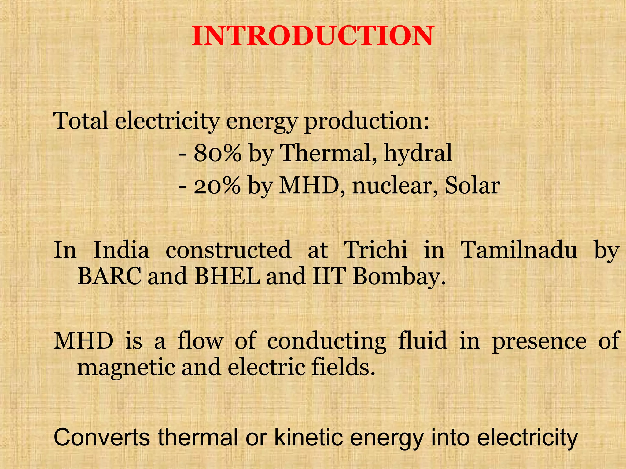
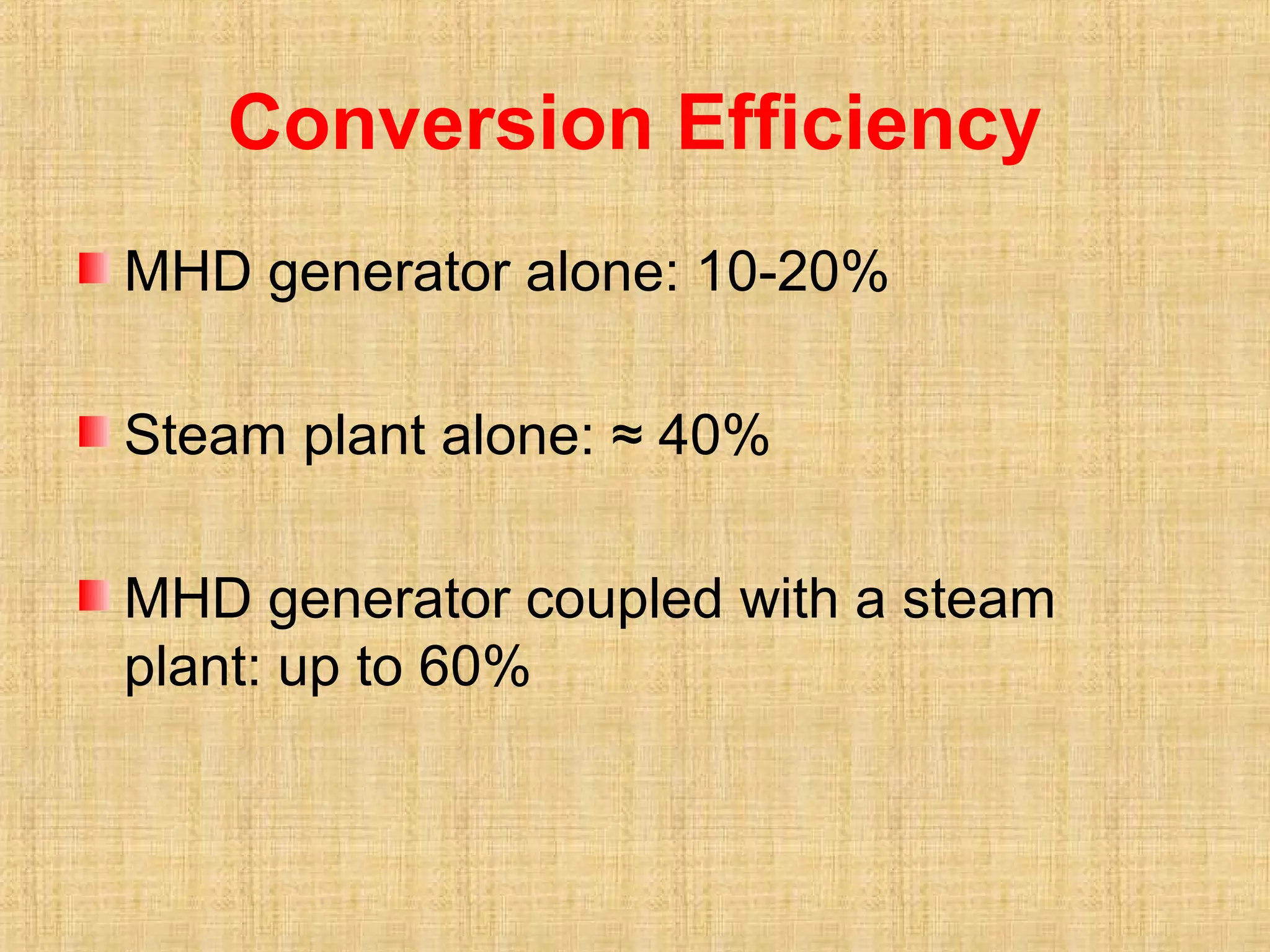
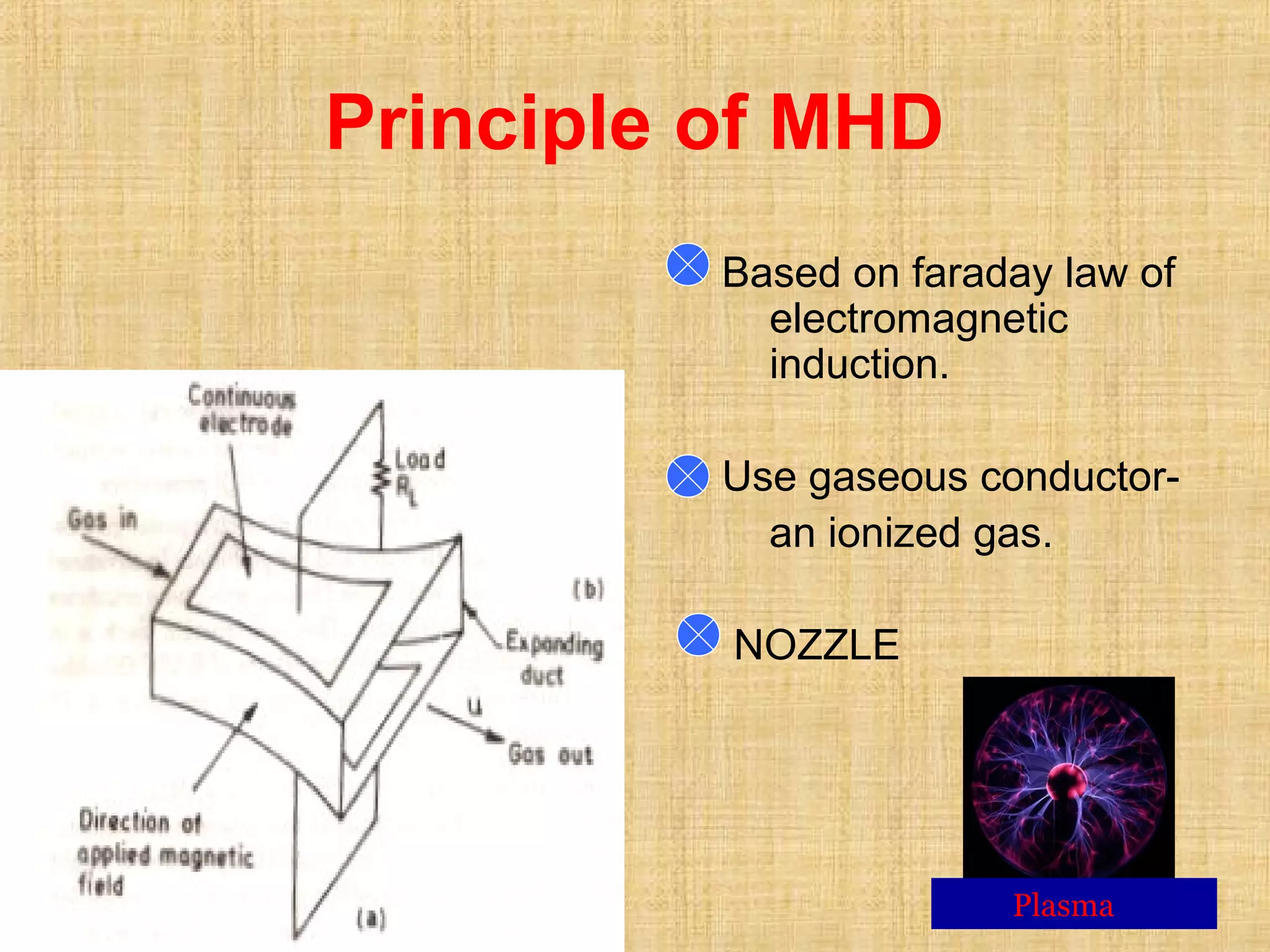
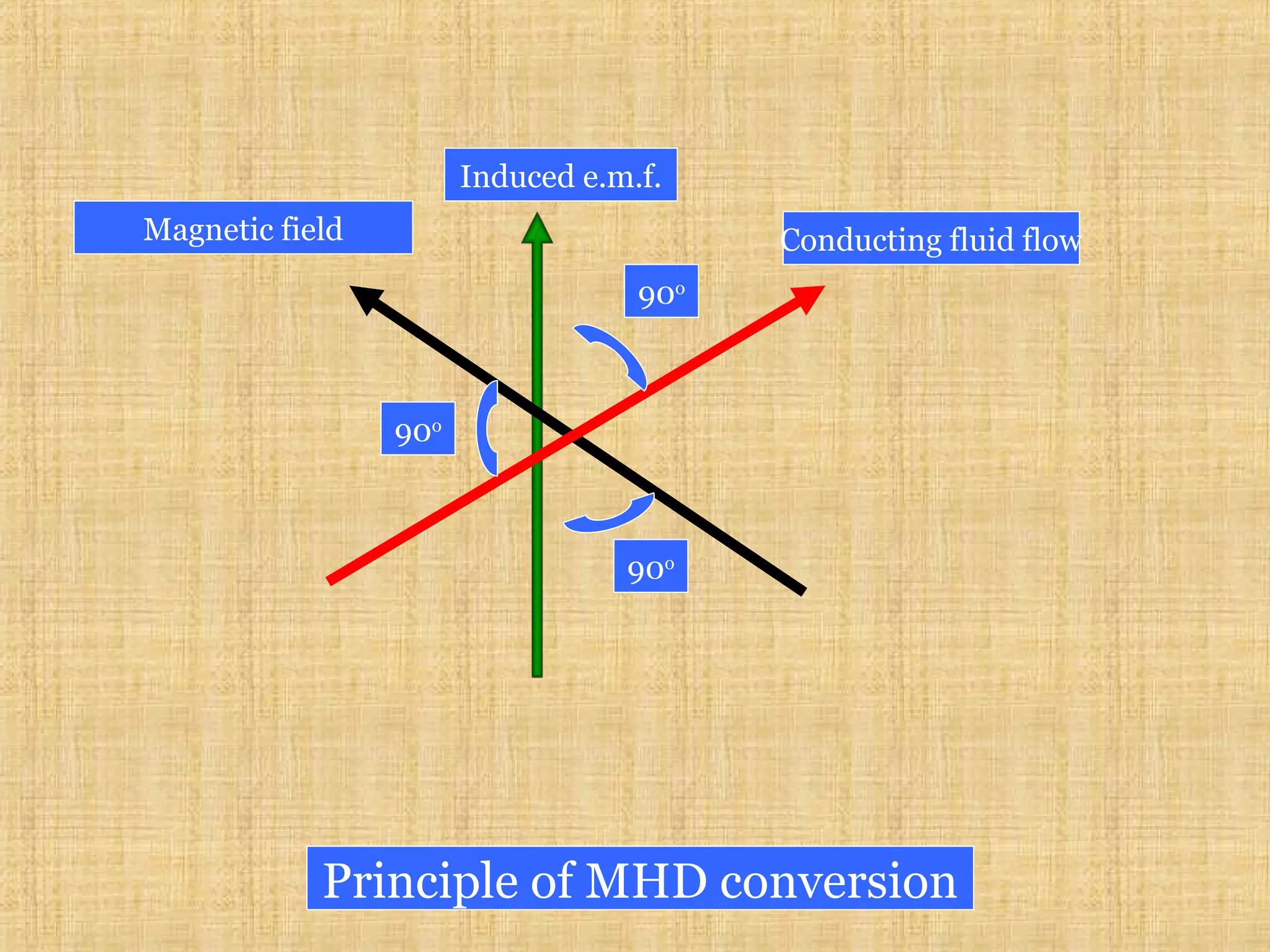
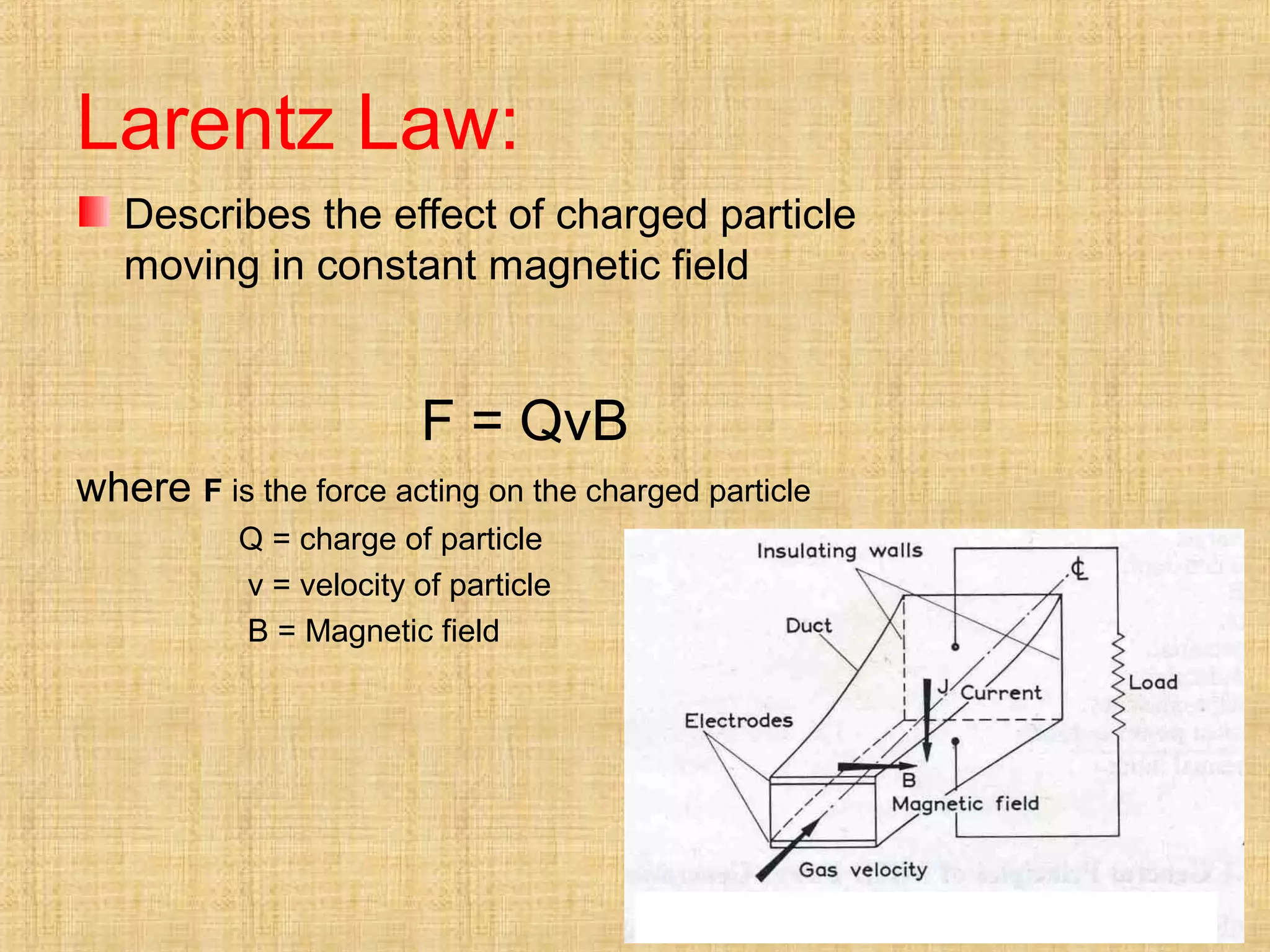
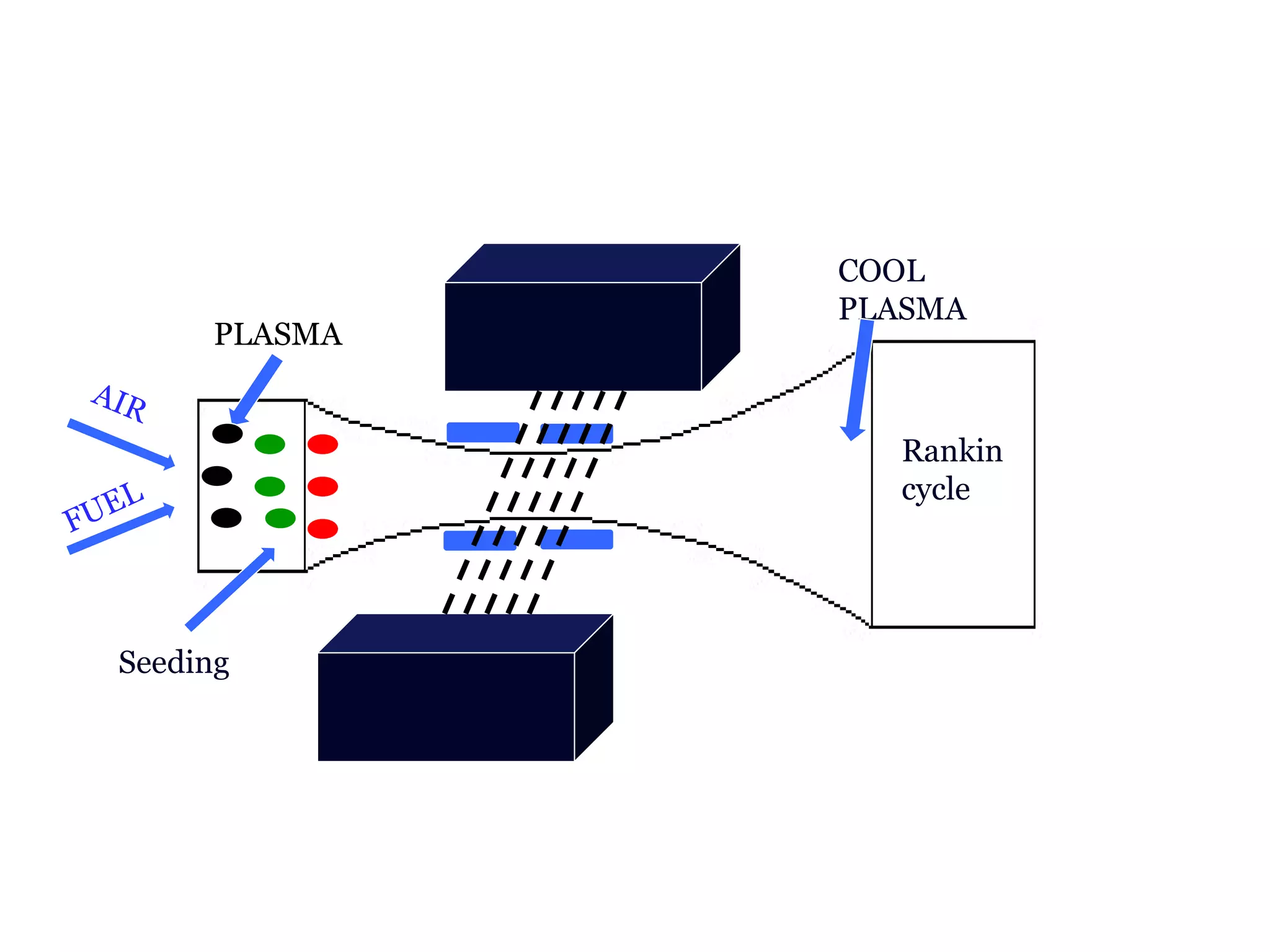
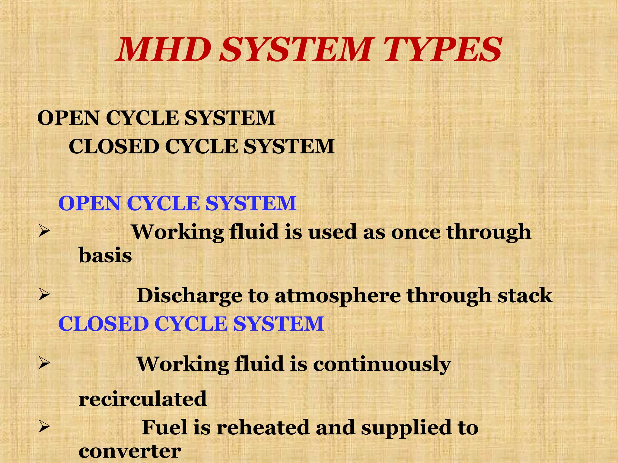
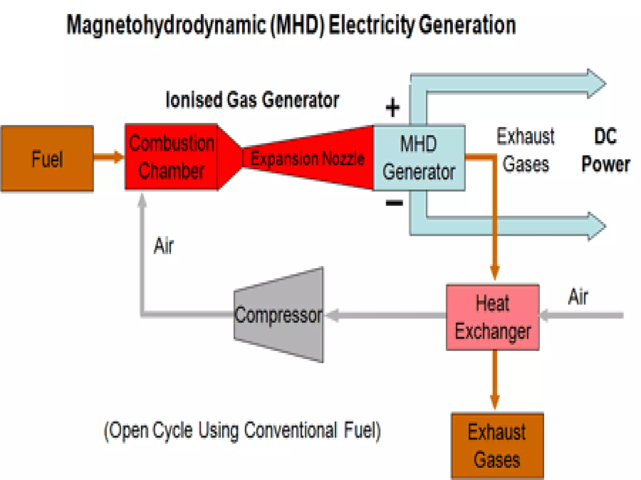
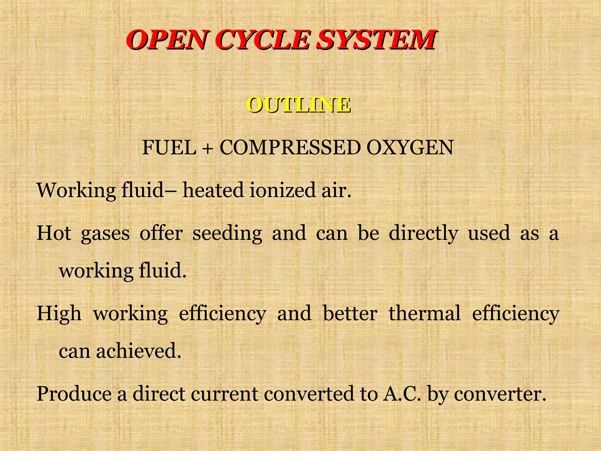
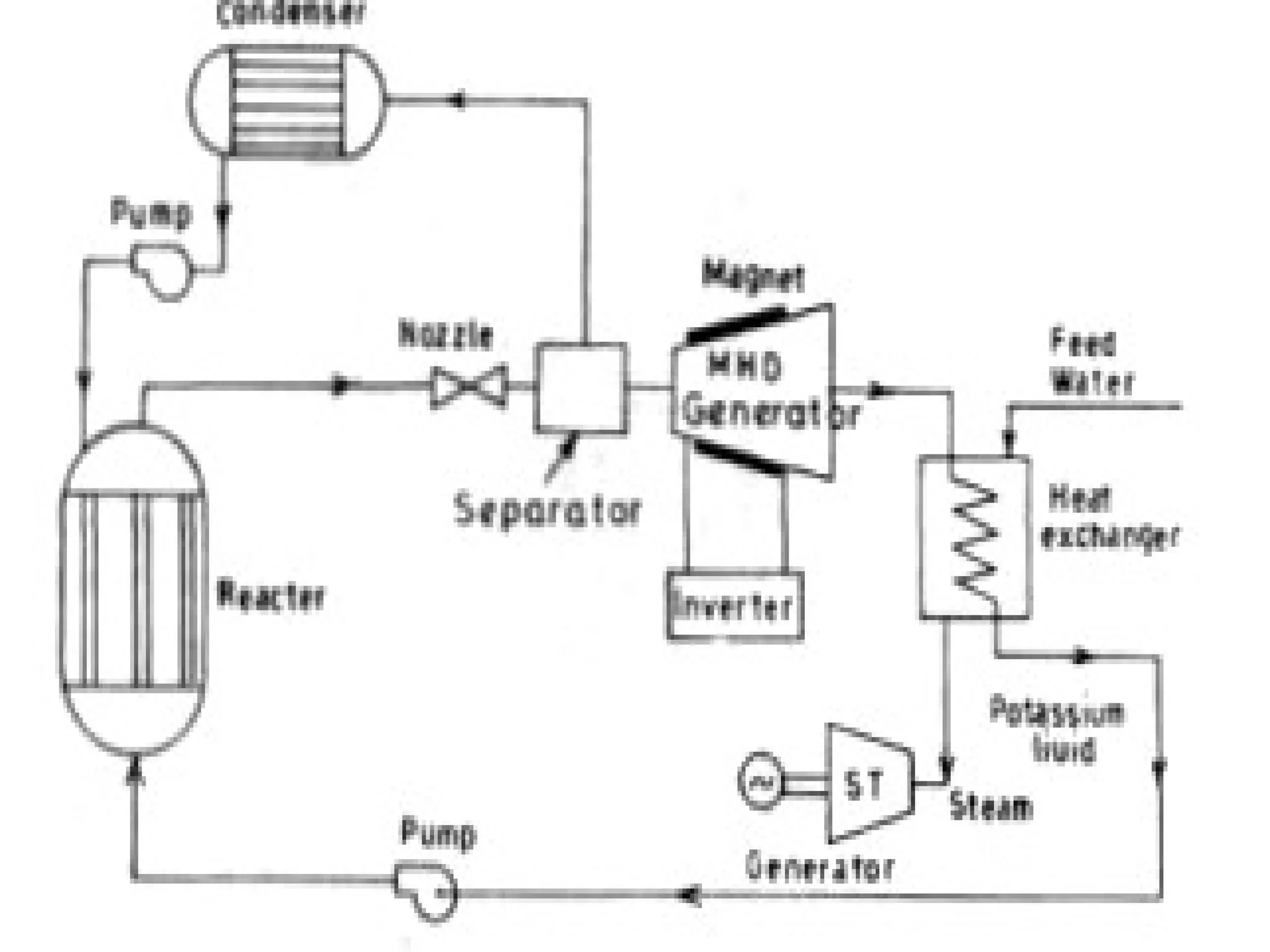
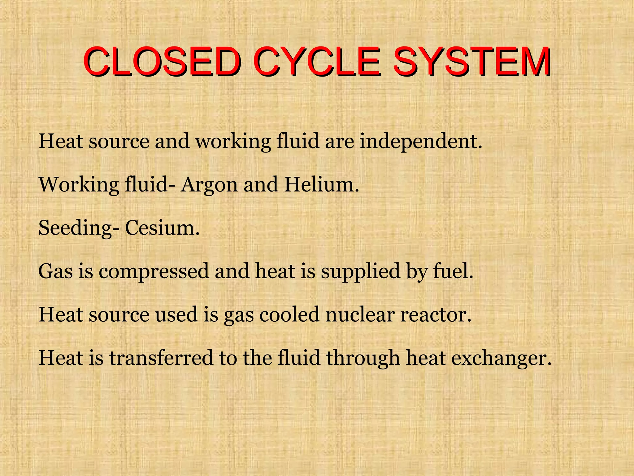
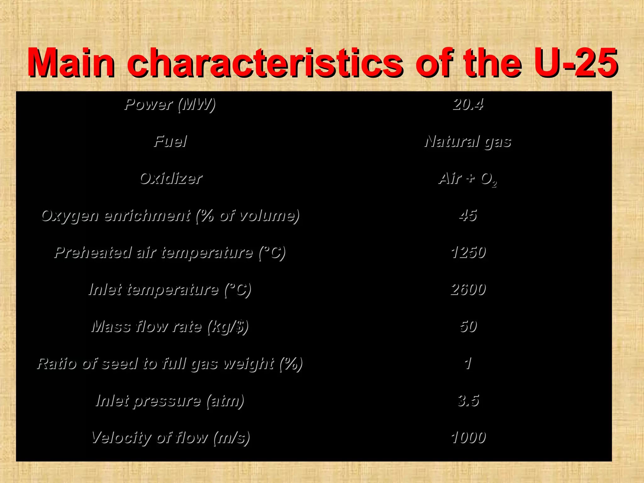
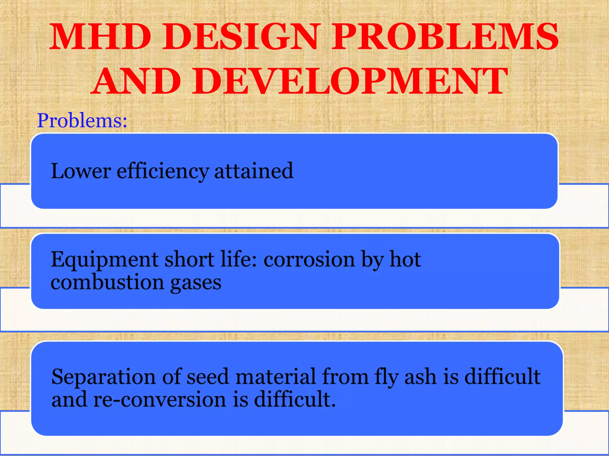
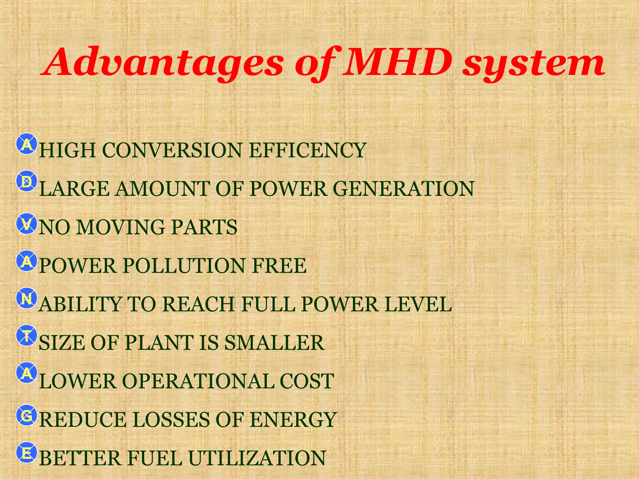
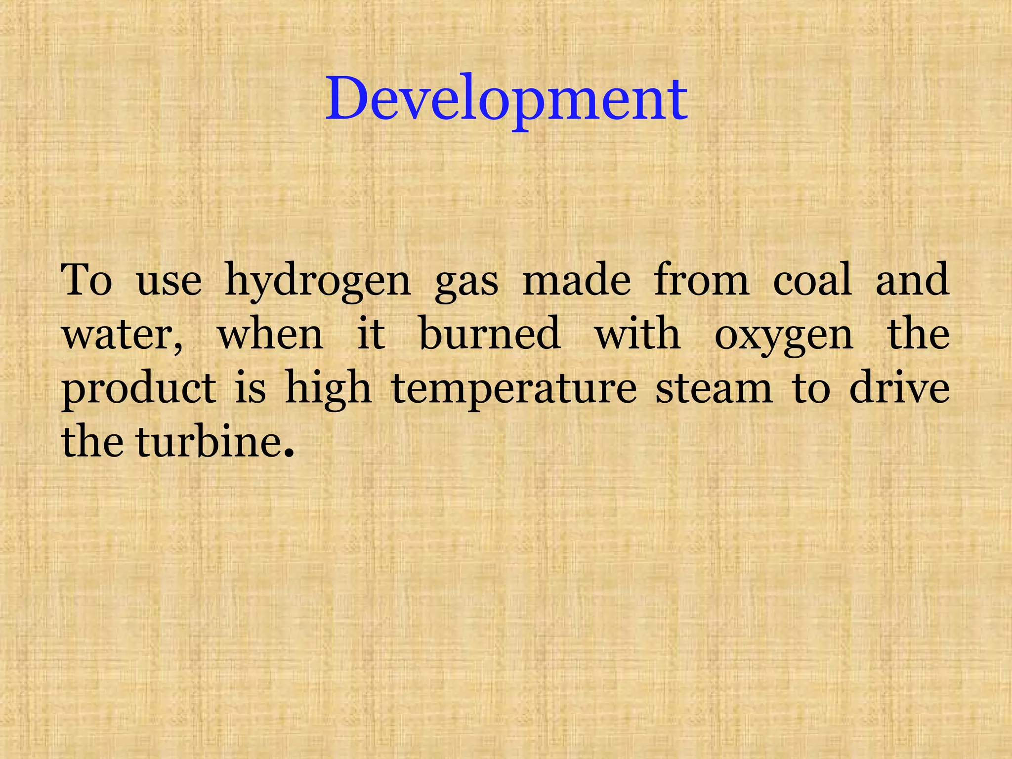
MAGNETO HYDRO DYNAMIC
POWER GENERATION
Miss. Madhuri More
Ph. D Scholar
REE, CTAE, MPUAT, Udaipur
INTRODUCTION
PRINCIPLE OF WORKING
TYPES OF MHD SYSTEMS
DESIGN PROBLEMS AND DEVELOPMENT
ADVANTAGES
TOPICS TO BE COVERED
T
O
P
I
C
MAGNETO HYDRO DYNAMIC
POWER GENERATION
Total electricity energy production:
- 80% by Thermal, hydral
- 20% by MHD, nuclear, Solar
In India constructed at Trichi in Tamilnadu by
BARC and BHEL and IIT Bombay.
MHD is a flow of conducting fluid in presence of
magnetic and electric fields.
Converts thermal or kinetic energy into electricity
INTRODUCTION
Conversion Efficiency
MHD generator alone: 10-20%
Steam plant alone: ≈ 40%
MHD generator coupled with a steam
plant: up to 60%
Principle of MHD
Based on faraday law of
electromagnetic
induction.
Use gaseous conductor-
an ionized gas.
NOZZLE
Plasma
Conducting fluid flowMagnetic field
Induced e.m.f.
90o
90o
90o
Principle of MHD conversion
Larentz Law:
Describes the effect of charged particle
moving in constant magnetic field
F = QvB
where F is the force acting on the charged particle
Q = charge of particle
v = velocity of particle
B = Magnetic field
AIR
PLASMA
COOL
PLASMA
Magnet
Rankin
cycle
Seeding
FUEL
Increasing the conductivity of gas.
Temperature increment = 0
1% of total mass flow
Cesium & potassium.
Conductivity achieved between 10-
100 mhos/m in temperature 2000-
2400 o
k.
SEEDING
OPEN CYCLE SYSTEM
CLOSED CYCLE SYSTEM
OPEN CYCLE SYSTEM
 Working fluid is used as once through
basis
 Discharge to atmosphere through stack
CLOSED CYCLE SYSTEM
 Working fluid is continuously
recirculated
 Fuel is reheated and supplied to
converter
MHD SYSTEM TYPES
OPEN CYCLE SYSTEMOPEN CYCLE SYSTEM
OUTLINEOUTLINE
FUEL + COMPRESSED OXYGEN
Working fluid– heated ionized air.
Hot gases offer seeding and can be directly used as a
working fluid.
High working efficiency and better thermal efficiency
can achieved.
Produce a direct current converted to A.C. by converter.
OPEN CYCLE SYSTEMOPEN CYCLE SYSTEM
CLOSED CYCLE SYSTEMCLOSED CYCLE SYSTEM
Heat source and working fluid are independent.
Working fluid- Argon and Helium.
Seeding- Cesium.
Gas is compressed and heat is supplied by fuel.
Heat source used is gas cooled nuclear reactor.
Heat is transferred to the fluid through heat exchanger.
REVIEWREVIEW
In 1970's the High Temperature Institute
of The Ussr Academy Of Sciences
constructed the first largefirst large MHD pilot plant
U-25U-25
Seeding- Alkaline metalSeeding- Alkaline metal
Main characteristics of the U-25Main characteristics of the U-25
Power (MW)Power (MW) 20.420.4
FuelFuel Natural gasNatural gas
OxidizerOxidizer Air + OAir + O22
Oxygen enrichment (% of volume)Oxygen enrichment (% of volume) 4545
Preheated air temperature (°C)Preheated air temperature (°C) 12501250
Inlet temperature (°C)Inlet temperature (°C) 26002600
Mass flow rate (kg/$)Mass flow rate (kg/$) 5050
Ratio of seed to full gas weight (%)Ratio of seed to full gas weight (%) 11
Inlet pressure (atm)Inlet pressure (atm) 3.53.5
Velocity of flow (m/s)Velocity of flow (m/s) 10001000
MHD DESIGN PROBLEMS
AND DEVELOPMENT
Problems:
.
Advantages of MHD system
HIGH CONVERSION EFFICENCY
LARGE AMOUNT OF POWER GENERATION
NO MOVING PARTS
POWER POLLUTION FREE
ABILITY TO REACH FULL POWER LEVEL
SIZE OF PLANT IS SMALLER
LOWER OPERATIONAL COST
REDUCE LOSSES OF ENERGY
BETTER FUEL UTILIZATION
A
D
V
A
N
T
A
G
E
Development
To use hydrogen gas made from coal and
water, when it burned with oxygen the
product is high temperature steam to drive
the turbine.
ReferencesReferences
Non conventional energy sources; G.D.Non conventional energy sources; G.D.
Rai.Rai.
Magnetohydrodynamic (MHD) PowerMagnetohydrodynamic (MHD) Power
Generation; Wikipedia.Generation; Wikipedia.
Magneto hydro dynamic system

Magneto hydro dynamic system

  • 1.
    MAGNETO HYDRO DYNAMIC POWERGENERATION Miss. Madhuri More Ph. D Scholar REE, CTAE, MPUAT, Udaipur
  • 2.
    INTRODUCTION PRINCIPLE OF WORKING TYPESOF MHD SYSTEMS DESIGN PROBLEMS AND DEVELOPMENT ADVANTAGES TOPICS TO BE COVERED T O P I C MAGNETO HYDRO DYNAMIC POWER GENERATION
  • 3.
    Total electricity energyproduction: - 80% by Thermal, hydral - 20% by MHD, nuclear, Solar In India constructed at Trichi in Tamilnadu by BARC and BHEL and IIT Bombay. MHD is a flow of conducting fluid in presence of magnetic and electric fields. Converts thermal or kinetic energy into electricity INTRODUCTION
  • 4.
    Conversion Efficiency MHD generatoralone: 10-20% Steam plant alone: ≈ 40% MHD generator coupled with a steam plant: up to 60%
  • 5.
    Principle of MHD Basedon faraday law of electromagnetic induction. Use gaseous conductor- an ionized gas. NOZZLE Plasma
  • 6.
    Conducting fluid flowMagneticfield Induced e.m.f. 90o 90o 90o Principle of MHD conversion
  • 7.
    Larentz Law: Describes theeffect of charged particle moving in constant magnetic field F = QvB where F is the force acting on the charged particle Q = charge of particle v = velocity of particle B = Magnetic field
  • 8.
  • 10.
    Increasing the conductivityof gas. Temperature increment = 0 1% of total mass flow Cesium & potassium. Conductivity achieved between 10- 100 mhos/m in temperature 2000- 2400 o k. SEEDING
  • 11.
    OPEN CYCLE SYSTEM CLOSEDCYCLE SYSTEM OPEN CYCLE SYSTEM  Working fluid is used as once through basis  Discharge to atmosphere through stack CLOSED CYCLE SYSTEM  Working fluid is continuously recirculated  Fuel is reheated and supplied to converter MHD SYSTEM TYPES
  • 12.
  • 13.
    OUTLINEOUTLINE FUEL + COMPRESSEDOXYGEN Working fluid– heated ionized air. Hot gases offer seeding and can be directly used as a working fluid. High working efficiency and better thermal efficiency can achieved. Produce a direct current converted to A.C. by converter. OPEN CYCLE SYSTEMOPEN CYCLE SYSTEM
  • 15.
    CLOSED CYCLE SYSTEMCLOSEDCYCLE SYSTEM Heat source and working fluid are independent. Working fluid- Argon and Helium. Seeding- Cesium. Gas is compressed and heat is supplied by fuel. Heat source used is gas cooled nuclear reactor. Heat is transferred to the fluid through heat exchanger.
  • 16.
    REVIEWREVIEW In 1970's theHigh Temperature Institute of The Ussr Academy Of Sciences constructed the first largefirst large MHD pilot plant U-25U-25 Seeding- Alkaline metalSeeding- Alkaline metal
  • 17.
    Main characteristics ofthe U-25Main characteristics of the U-25 Power (MW)Power (MW) 20.420.4 FuelFuel Natural gasNatural gas OxidizerOxidizer Air + OAir + O22 Oxygen enrichment (% of volume)Oxygen enrichment (% of volume) 4545 Preheated air temperature (°C)Preheated air temperature (°C) 12501250 Inlet temperature (°C)Inlet temperature (°C) 26002600 Mass flow rate (kg/$)Mass flow rate (kg/$) 5050 Ratio of seed to full gas weight (%)Ratio of seed to full gas weight (%) 11 Inlet pressure (atm)Inlet pressure (atm) 3.53.5 Velocity of flow (m/s)Velocity of flow (m/s) 10001000
  • 18.
    MHD DESIGN PROBLEMS ANDDEVELOPMENT Problems: .
  • 19.
    Advantages of MHDsystem HIGH CONVERSION EFFICENCY LARGE AMOUNT OF POWER GENERATION NO MOVING PARTS POWER POLLUTION FREE ABILITY TO REACH FULL POWER LEVEL SIZE OF PLANT IS SMALLER LOWER OPERATIONAL COST REDUCE LOSSES OF ENERGY BETTER FUEL UTILIZATION A D V A N T A G E
  • 20.
    Development To use hydrogengas made from coal and water, when it burned with oxygen the product is high temperature steam to drive the turbine.
  • 21.
    ReferencesReferences Non conventional energysources; G.D.Non conventional energy sources; G.D. Rai.Rai. Magnetohydrodynamic (MHD) PowerMagnetohydrodynamic (MHD) Power Generation; Wikipedia.Generation; Wikipedia.