The document discusses several topics related to magnetic effects of electric currents:
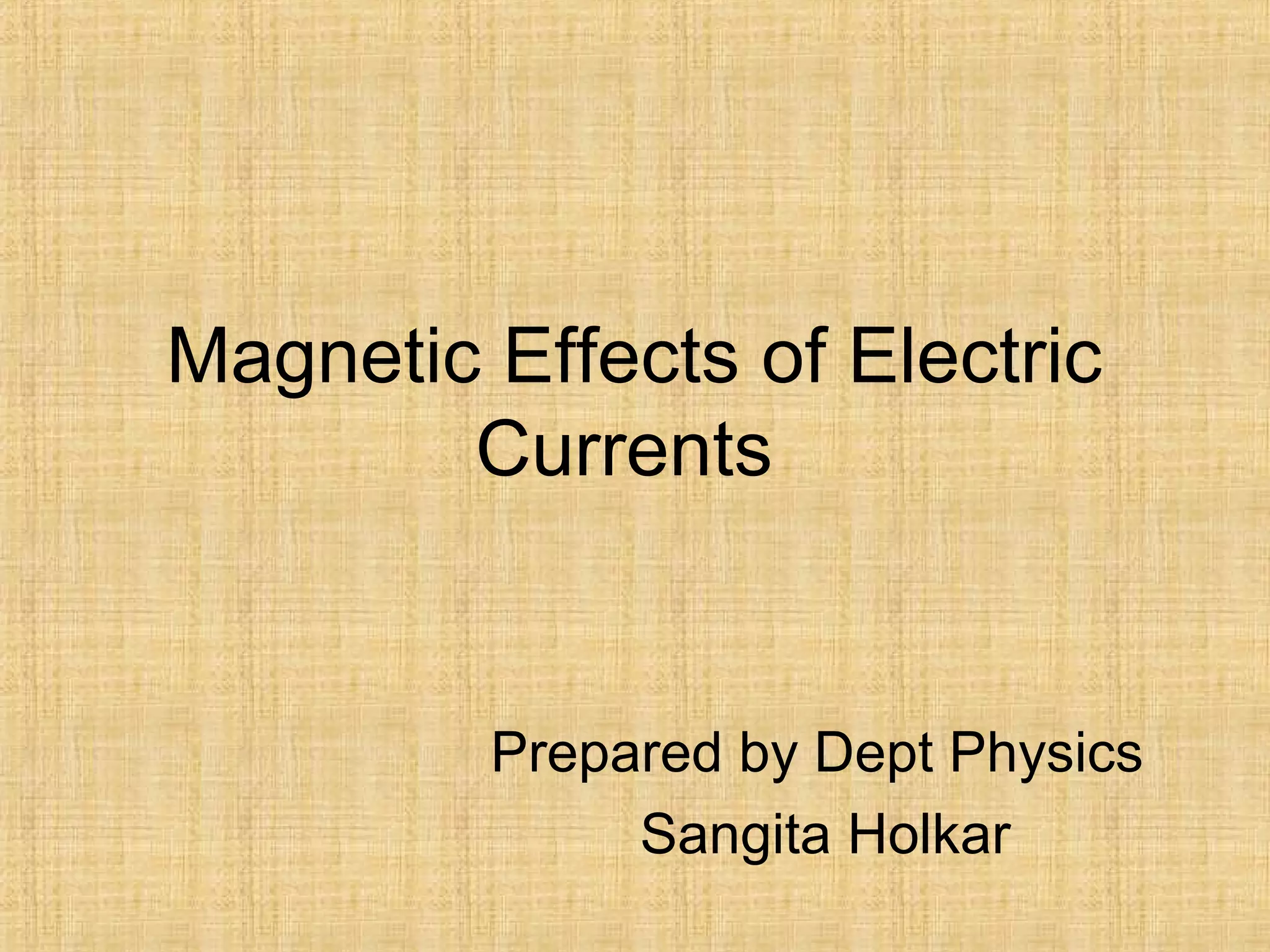
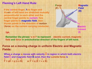
1. Lorentz force law describes the force experienced by a moving charge in a magnetic field. Fleming's left hand rule indicates the direction of this force.
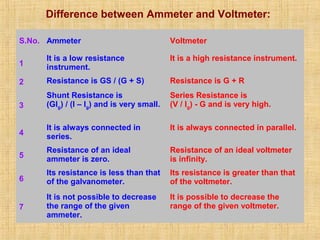
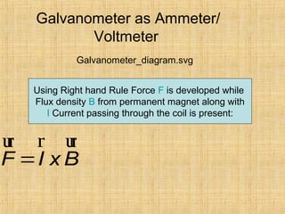
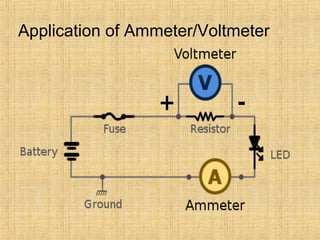
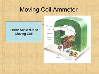
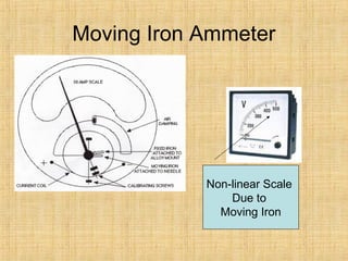
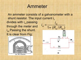
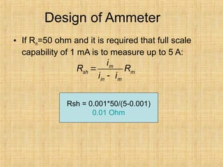
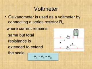
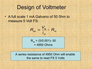
2. Instruments like galvanometers, ammeters, and voltmeters make use of the magnetic force on a current-carrying coil. Galvanometers can be adapted into ammeters using a shunt resistor or voltmeters using a series resistor.
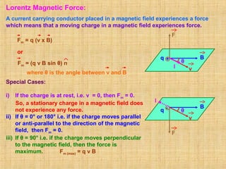
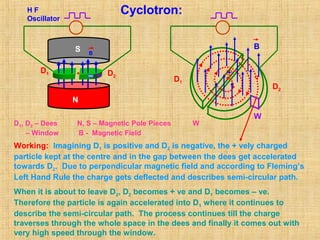
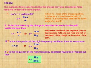
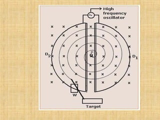
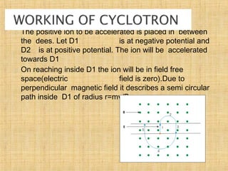
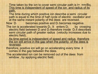
3. Other topics covered include the magnetic field due to parallel currents, torque on a current-carrying coil, cyclotron particle acceleration, and the maximum energy attainable by particles in a cyclotron.
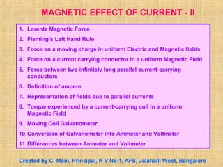
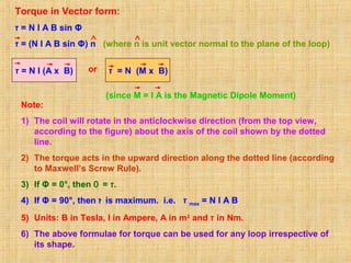
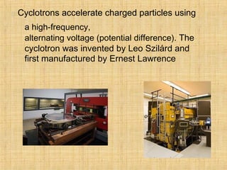
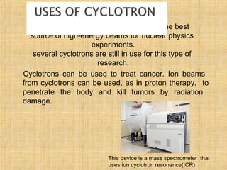
![Force on a current-carrying conductor in a uniform
Magnetic Field:
θ
vd
dl
F
I
I
B
A l
Force experienced by each electron in
the conductor is
f = - e (vd x B)
If n be the number density of electrons,
A be the area of cross section of the
conductor, then no. of electrons in the
element dl is n A dl.
where I = neAvd and -ve sign represents that
the direction of dl is opposite to that of vd)
or F = I l B sin θ
-
Force experienced by the electrons in dl is
dF = n A dl [ - e (vd x B)] = - n e A vd (dl X B)
= I (dl x B)
F = ∫ dF = ∫ I (dl x B)
F = I (l x B)](https://image.slidesharecdn.com/magneticeffects-151017114454-lva1-app6891/85/Magnetic-effects-5-320.jpg)
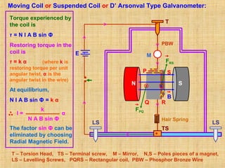
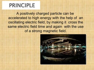
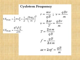
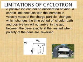
![Maximum Energy of the Particle:
Kinetic Energy of the charged particle is
K.E. = ½ m v2
= ½ m (
B q r
m
)2 = ½
B2
q2
r2
m
Maximum Kinetic Energy of the charged particle is when r = R (radius of the D’s).
= ½
B2
q2
R2
m
K.E. max
The expressions for Time period and Cyclotron frequency only when
m remains constant. (Other quantities are already constant.)
m =
m0
[1 – (v2
/ c2
)]½
If frequency is varied in synchronisation with the variation of mass of the
charged particle (by maintaining B as constant) to have resonance, then the
cyclotron is called synchro – cyclotron.
If magnetic field is varied in synchronisation with the variation of mass of
the charged particle (by maintaining f as constant) to have resonance, then
the cyclotron is called isochronous – cyclotron.
NOTE: Cyclotron can not be used for accelerating neutral particles. Electrons can
not be accelerated because they gain speed very quickly due to their lighter mass
and go out of phase with alternating e.m.f. and get lost within the dees.
But m varies with v according to
Einstein’s Relativistic Principle as per](https://image.slidesharecdn.com/magneticeffects-151017114454-lva1-app6891/85/Magnetic-effects-24-320.jpg)


![[Electricity and Magnetism] Electrodynamics](https://cdn.slidesharecdn.com/ss_thumbnails/engineeringphysicsed-150823041844-lva1-app6891-thumbnail.jpg?width=640&height=640&fit=bounds)


![P2B_P4_part_1_MOVING_CHARGES_AND_MAGNETISM[1] - Read-Only-1.pdf](https://cdn.slidesharecdn.com/ss_thumbnails/p2bp4part1movingchargesandmagnetism1-read-only-1-240804234951-2886f58e-thumbnail.jpg?width=640&height=640&fit=bounds)


