MAGNETIC EFFECTS OFCURRENT
ALL DERIVATIONS
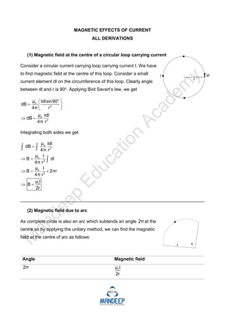
(1) Magnetic field at the centre of a circular loop carrying current
Consider a circular current carrying loop carrying current I. We have
to find magnetic field at the centre of this loop. Consider a small
current element dl on the circumference of this loop. Clearly angle
between dl and r is 90o. Applying Biot Savart’s law, we get
o
o
2
o
2
μ Idlsin90
dB
4π r
μ Idl
dB
4π r
Integrating both sides we get
o
2
o
2
o
2
o
μ Idl
dB
4π r
μ I
B dl
4π r
μ I
B 2πr
4π r
μ I
B
2r
_________________________________________________________________________
(2) Magnetic field due to arc
As complete circle is also an arc which subtends an angle 2πat the
centre so by applying the unitary method, we can find the magnetic
field at the centre of arc as follows:
Angle Magnetic field
2π o
μ I
2r
2.
1 radian oo
μ I μ I
1
2r 2π 4πr
Any angle θ
o
μ I
B θ
4πr
_________________________________________________________________________
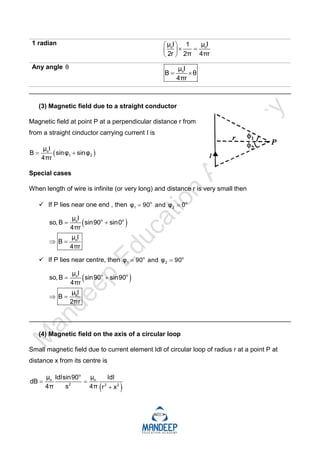
(3) Magnetic field due to a straight conductor
Magnetic field at point P at a perpendicular distance r from
from a straight cinductor carrying current I is
o
1 2
μ I
B sinφ sinφ
4πr
Special cases
When length of wire is infinite (or very long) and distance r is very small then
If P lies near one end , then o o
1 2
φ 90 and φ 0
o o
o
o
μ I
so, B sin90 sin0
4πr
μ I
B
4πr
If P lies near centre, then o o
1 2
φ 90 and φ 90
o o
o
o
μ I
so, B sin90 sin90
4πr
μ I
B
2πr
_________________________________________________________________________
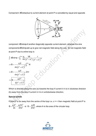
(4) Magnetic field on the axis of a circular loop
Small magnetic field due to current element Idl of circular loop of radius r at a point P at
distance x from its centre is
o
o o
2 2 2
μ μ
Idlsin90 Idl
dB
4π s 4π r x
3.
Component dBcosφdue tocurrent element at point P is cancelled by equal and opposite
component dBcosφof another diagonally opposite current element, whereas the sine
componentsdBsinφadd up to give net magnetic field along the axis. So net magnetic field
at point P due to entire loop is
2πr
o
1/2
2 2
0 2 2
2πr
o
3 0
2 2 2
o
3
2 2 2
2
o
3
2 2 2
μ Idl r
dBsinφ .
4π r x r x
μ Ir
B dl
4π r x
μ Ir
B .2πr
4π r x
μ Ir
B .
2 r x
Which is directed along the axis (a) towards the loop if current in it is in clockwise direction
(b) away from the loop if current in it is in anticlockwise direction.
Special points
If point P is far away from the centre of the loop i.e. x >> r then magnetic field at point P is
2 2
o o o
3 3
μ Ir μ Iπr μ IA
B or B
2x 2πx 2πx
where A is the area of the circular loop.
4.
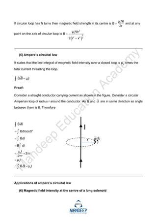
If circular loophas N turns then magnetic field strength at its centre is o
μ NI
B
2r
and at any
point on the axis of circular loop is
2
o
3
2 2 2
μ NIr
B
2 r x
_________________________________________________________________________
(5) Ampere’s circuital law
It states that the line integral of magnetic field intensity over a closed loop is o
μ times the
total current threading the loop.
o
B.dl μ I
Proof:
Consider a straight conductor carrying current as shown in the figure. Consider a circular
Amperian loop of radius r around the conductor. As B and dl
are in same direction so angle
between them is 0. Therefore
o
o
o
o
B.dl
Bdlcos0
Bdl
B dl
μ I
2πr
2πr
μ I
B.dl μ I
_________________________________________________________________________
Applications of ampere’s circuital law
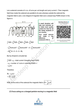
(6) Magnetic field intensity at the centre of a long solenoid
5.
Let a solenoidconsists of n no. of turns per unit length and carry current I. Then magnetic
field lines inside the solenoid are parallel to its axis whereas outside the solenoid the
magnetic field is zero. Line integral of magnetic field over a closed loop PQRS shown in the
figure is
Q R S P
P Q R S
B.dl B.dl B.dl B.dl B.dl
Q R P
o o o
P Q S
Q
P
B.dlcos0 B.dlcos90 0 B.dlcos90
B dl 0 0 0 BL
But by Ampere’s circuital law
o
o
o
B.dl μ total current threading loop PQRS
μ number of turns in solenoid PQRS I
μ nLI
Therefore
o
o
BL μ nLI
B μ nI
Note: at the ends of the solenoid the magnetic field is o
1
B μ nI
2
_________________________________________________________________________
(7) Force acting on a charged particle moving in a magnetic field
6.
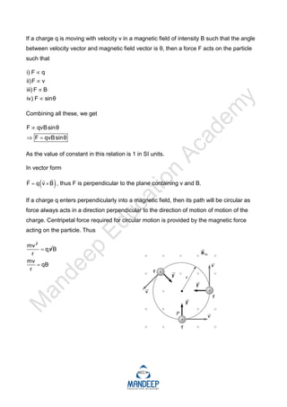
If a chargeq is moving with velocity v in a magnetic field of intensity B such that the angle
between velocity vector and magnetic field vector is θ, then a force F acts on the particle
such that
i) F q
ii)F v
iii) F B
iv) F sinθ
Combining all these, we get
F qvBsinθ
F qvBsinθ
As the value of constant in this relation is 1 in SI units.
In vector form
F q v B
, thus F is perpendicular to the plane containing v and B.
If a charge q enters perpendicularly into a magnetic field, then its path will be circular as
force always acts in a direction perpendicular to the direction of motion of motion of the
charge. Centripetal force required for circular motion is provided by the magnetic force
acting on the particle. Thus
2
mv
q v
r
B
mv
qB
r
7.
1. Radius ofthe path (r)
mv
r
Bq
2. Velocity (v)
Bqr
v
m
3. Time period (T)
2πr 2π r
T
v
Bqr
2πm
Bq
m
4. Frequency
1 Bq
v
T 2πm
5. Angular frequency
Bq Bq
ω 2πv 2π
2πm m
6. Kinetic energy
2
2
1 1 Bqr
KE mv m
2 2 m
1
KE m
2
2 2 2
2
B q r
m
2 r 2
1 B q r
2 m
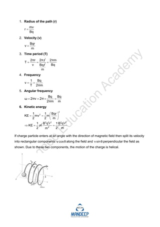
If charge particle enters at an angle with the direction of magnetic field then split its velocity
into rectangular components v cosθ along the field and v sinθ perpendicular the field as
shown. Due to these two components, the motion of the charge is helical.
8.
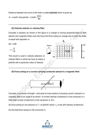
Distance between twoturns of the helix is called pitch(d) which is given by
2πm
d vcosθ time period vcosθ
Bq
_________________________________________________________________________
(8) Velocity selector or velocity filter
Consider a situation as shown in the figure in a charge is moving perpendicularly to both
electric and magnetic fields such the force the force acting on charge due to both the fields
is equal and opposite i.e.
qE = qvB
E
v
B
This result is used in velocity selectors or
velocity filters in which we have to select a
particle with a particular value of velocity.
_________________________________________________________________________
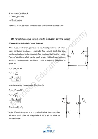
(9) Force acting on a current carrying conductor placed in a magnetic field
Consider a conductor of length and area of cross section A carrying current I placed in a
magnetic field at an angle θ as shown. If number density of electrons in the conductor is n
then total number of electrons in the conductor is A n
.
As force acting on one electron is d
f ev Bsinθ
where d
v is the drift velocity of electrons.
So the total force acting on the conductor is
9.
d
d
Anf A n ev Bsinθ
Anev Bsinθ
F I Bsinθ
Direction of this force can be determined by Fleming’s left hand rule.
_________________________________________________________________________
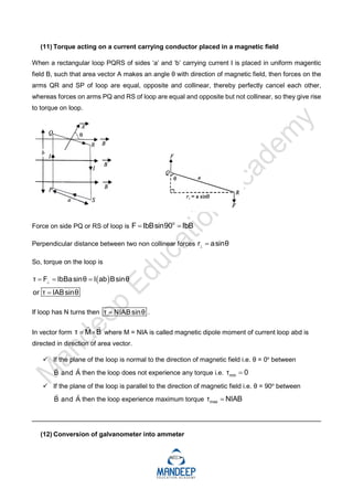
(10) Force between two parallel straight conductors carrying current
When the currents are in same direction
When two current carrying conductors are placed parallel to each other,
each conductor produces a magnetic field around itself. So, one
conductor is placed in the magnetic field produced by the other. Using
Fleming’s left hand rule it can be easily shown that the forces on them
are such that they attract each other. Force acting on 1st
conductor is
given as
o
1 1 2
o 2
1 1
o 1 2
1
F I B sin90
μ I
F I
2πr
μ II
F
2πr
Now force acting on conductor 2 is given by
o
2 2 1
o 1
2 2
o 1 2
2
F I B sin90
μ I
F I
2πr
μ II
F
2πr
Therefore 1 2
F F
Note: When the current is in opposite direction the conductors
will repel each other the magnitude of force will be same as
derived above.
_________________________________________________________________________
10.
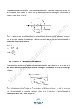
(11) Torque actingon a current carrying conductor placed in a magnetic field
When a rectangular loop PQRS of sides ‘a’ and ‘b’ carrying current I is placed in uniform magentic
field B, such that area vector A makes an angle θ with direction of magnetic field, then forces on the
arms QR and SP of loop are equal, opposite and collinear, thereby perfectly cancel each other,
whereas forces on arms PQ and RS of loop are equal and opposite but not collinear, so they give rise
to torque on loop.
Force on side PQ or RS of loop is
o
F IbBsin90 IbB
Perpendicular distance between two non collinear forces r asinθ
So, torque on the loop is
τ F IbBasinθ I ab Bsinθ
or τ IABsinθ
If loop has N turns then τ NIAB sinθ
.
In vector form τ M B
where M = NIA is called magnetic dipole moment of current loop abd is
directed in direction of area vector.
If the plane of the loop is normal to the direction of magnetic field i.e. θ = 0o
between
B and A
then the loop does not experience any torque i.e. min
τ 0
If the plane of the loop is parallel to the direction of magnetic field i.e. θ = 90o
between
B and A
then the loop experience maximum torque max
τ NIAB
_________________________________________________________________________
(12) Conversion of galvanometer into ammeter
11.
A galvanometer canbe converted into ammeter by connecting a low shunt resistance in parallel with
it, so that most of the current by passes through the shunt resistance, enabling the galvanometer to
measure much larger currents.
Thus if a galvanometer of resistance Rg which gives full scale deflection at g
I is to be used to convert
into an ammeter capable of measuring a maximum current I , we connect a shunt resistance R in
parallel with it which is obtained as
R G
g g g
g g
g
V V
I I R I R
I R
R
I I
_________________________________________________________________________
(13) Conversion of galvanometer into voltmeter
A galvanometer can be converted into voltmeter by connecting high resistance in series with it, so
that most of the voltage applied drops across it, enabling the galvanometer to measure much larger
voltages.
Thus is the galvanometer of resistance g
R which gives full deflection at current g
I , is to be converted
into voltmeter capable of measuring maximum voltage up to V volts, then a high resistance R is
connected in series with it which is given by
12.
g g gg g g
g
g
V I R I R or V I R I R
V
or R R
I


![P2B_P4_part_1_MOVING_CHARGES_AND_MAGNETISM[1] - Read-Only-1.pdf](https://cdn.slidesharecdn.com/ss_thumbnails/p2bp4part1movingchargesandmagnetism1-read-only-1-240804234951-2886f58e-thumbnail.jpg?width=640&height=640&fit=bounds)