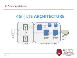
Broadband Wireless Technology
Module 5:Evolution of LTE Technology beyond
3G
Dr. Manoj M Dongre
Module 5:
Evolution of LTE Technology beyond 3G
Syllabus
 Module 5:Evolution of LTE Technology beyond 3G
 4TH Generation Mobile Network, 4G Network architecture ,feature
framework ,planning overview for 4G network, challenges and
limitation of 4G Network,5G Roadmap, Pillers of 5G, 5G
Architecture , overview of Cognitive Radio technology in 5G.
 Sources:
• Jonathan Rodriguez,” Fundamentals of 5G Mobile Networks,Wiley Publication
• Ajay R. Mishra,” Advanced Cellular Networks Planning and Optimization”,Wiley
Publication
3
4TH Generation Mobile Network,
 4th generation networks would offer some exciting opportunities, such as
 Performance. The 4G systems are intended to provide high quality video
services providing data transfer speeds of about 100 Mbps.
 .Bandwidth. The 4G technology offers transmission speeds of more than
20 Mbps and is capable of
offering high bandwidth services within the reach of local area network
(LAN) hotspots, installed in airports, homes and offices.
 .Interoperability. The existence of multiple standards for 3G made it
difficult to roam and interoperate
across networks. There is therefore a need for a global standard
providing global mobility and service portability so that the single-system
vendors of proprietary equipment do not bind the customers.
 Technology. Rather than being an entirely new standard, 4G basically
resembles a conglomeration of
existing technologies and is a convergence of more than one
technology.
4
4G Network architecture
 4G stands for fourth generation cellular system.
 4G is evaluation of 3G to meet the forecasted rising demand.
 It is an integration of various technologies including
GSM,CDMA,GPRS,IMT-2000 ,Wireless LAN.
 Data rate in 4G system will range from 20 to 100 Mbps.
 Network architecture
 The high-level network architecture of LTE is comprised of following three
main components:
 The User Equipment (UE).
 The Evolved UMTS Terrestrial Radio Access Network (E-UTRAN).
 The Evolved Packet Core (EPC).
5
4G Network architecture
6
The User Equipment (UE)
 The internal architecture of the user equipment for LTE is identical to the
one used by UMTS and GSM which is actually a Mobile Equipment (ME).
 The mobile equipment comprised of the following important modules:
 Mobile Termination (MT) : This handles all the communication functions.
 Terminal Equipment (TE) : This terminates the data streams.
 Universal Integrated Circuit Card (UICC) : This is also known as the
SIM card for LTE equipments. It runs an application known as the
Universal Subscriber Identity Module (USIM).
 A USIM stores user-specific data very similar to 3G SIM card. This keeps
information about the user's phone number, home network identity and
security keys etc.
7
E-UTRAN
 The E-UTRAN (The access network)
 The E-UTRAN handles the radio communications between the mobile and the
evolved packet core the evolved base stations, called eNodeB or eNB.
 Each eNB is a base station that controls the mobiles in one or more cells. The base
station that is communicating with a mobile is known as its serving eNB.
 LTE Mobile communicates with just one base station and one cell at a time and
there are following two main functions supported by eNB:
 The eBN sends and receives radio transmissions to all the mobiles using the
analogue and digital signal processing functions of the LTE air interface.
 The eNB controls the low-level operation of all its mobiles, by sending them
signalling messages such as handover commands.
 Each eBN connects with the EPC by means of the S1 interface and it can also be
connected to nearby base stations by the X2 interface, which is mainly used for
signalling and packet forwarding during handover.
 A home eNB (HeNB) is a base station that has been purchased by a user to provide
femtocell coverage within the home.
 A home eNB belongs to a closed subscriber group (CSG) and can only be
accessed by mobiles with a USIM that also belongs to the closed subscriber group.
8
The Evolved Packet Core (EPC)
 The Evolved Packet Core (EPC) is the core network
 The Home Subscriber Server (HSS) component has been carried forward from
UMTS and GSM and is a central database that contains information about all the
network operator's subscribers.
 The Packet Data Network (PDN) Gateway (P-GW) communicates with the outside
world ie. packet data networks PDN, using SGi interface.
 Each packet data network is identified by an access point name (APN).
 The PDN gateway has the same role as the GPRS support node (GGSN) and the
serving GPRS support node (SGSN) with UMTS and GSM.
 The serving gateway (S-GW) acts as a router, and forwards data between the base
station and the PDN gateway.
 The mobility management entity (MME) controls the high-level operation of the
mobile by means of signaling messages and Home Subscriber Server (HSS).
 The Policy Control and Charging Rules Function (PCRF) is responsible for policy
control decision-making, as well as for controlling the flow-based charging
functionalities in the Policy Control Enforcement Function (PCEF), which resides in
the P-GW.
 There are few more components which have not been shown in the architecture .
These components are like the Earthquake and Tsunami Warning System (ETWS)
and the Equipment Identity Register (EIR)
9
Feature Framework in the 4G Network
 The feature framework in the 4G network can be defined by using one simple word,
integration, i.e. seamless integration of terminals, networks and applications
together with users
 Apart from users, the domain includes targets such as terminals, networks and
applications.
 Convergence of the above mentioned targets.
 The adaptability of the features between different targets make integration
seamless
 Diversity in a 4G Network:
 The need for diversity in these networks is caused by external targets and is fulfilled
by internal targets. two kinds of diversity in 4G networks
 External Diversity
 This brings demand for adaptability features within targets. As it lies outside the
targets it is therefore called external diversity. External diversity of users refers to
people in different situations, e.g. back- ground, personal preference,etc
 Internal Diversity
 This gives the solution for adaptability. As it lies within the target it is therefore
called internal diversity.
 Internal diversity of users are people with different interfaces, e.g. hearing, speech,
etc.,
 While internal diversity of terminals means that one terminal may integrate multiple
10
Planning Overview for 4G networks
 Planning of 4G networks each of the individual networks GSM, EGPRS
and UMTS have been planned in their respective domains, e.g. radio,
transmission or core.
 Network planning in 4G networks will require an understanding of more
technologies,
 4G network will be an integrated wireless system that enables seamless
roaming between technologies,
 A user can be operating in a cellular technology network and then be
handed over to the satellite based network and back to a fixed wireless
network,
 Depending upon the network coverage and the user’s preference of
charging.
 Planning a network basically involves an initial layout of the system
structure, which includes the spectrum, cell radius and hierarchical service
area.
11
Planning Overview for 4G networks
 Spectrum
 The 4G systems are expected to provide bandwidths higher than 20 Mbps and to
accommodate a significantly increased amount of traffic, so sufficient frequency
resources will be required.
 Since the lower frequency band considered suitable for mobile communications is heavily
used, a frequency band for the 4G communications is to be proposed in the 3G to 5G
bands
 Cell Radius
 As planned, the bandwidth to be offered in 4G systems is three orders of magnitude
greater than that of 2G systems.
 The cell radius covered by a base station (BS) generally decreases if, assuming all other
conditions to be the same,
 Radio signals are transmitted at higher bit rates than at a lower transmission bit rate in
order to compensate for the increased noise level.
 4G systems may be operated in a higher frequency band so that propagation loss of the
wireless signal is higher than that of 2G and 3G systems.
 By covering the same area as in 3G systems, the 4G systems will require four
times the number of BSs.
 The antenna height of the BS in an urban area tends to be lower when the cell size
is smaller
 As a result, there may be more outage areas, even within the calculated cell radius,
12
Planning Overview for 4G networks
 Hierarchical Service Area
 Although all objects will be connected to a network through wireless links,
it may be difficult for small devices to be directly connected to 4G systems
due to power consumption and antenna size.
 Compact devices will be able to access the 4G systems through a
miniature base that will act as a mobile terminal (MT) for 4G systems.
 Employing such a configuration results in service areas consisting of
multiple overlapping cells.
13
Technologies Support for 4G
 OFDM
 OFDM is a digital modulation technique in which one time symbol waveform and thousands of
orthogonal waves are multiplexed, which is good for high bandwidth digital data transmission.
W-OFDM
 Wideband OFDM (W-OFDM) enables data to be encoded on multiple high speed radio
frequencies allowing greater security, an increased amount of data being sent and the most
efficient use of bandwidth.
 MC-CDMA
 MC-CDMA is actually an OFDM with a CDMA overlay.
 Users are multiplexed with orthogonal codes to distinguish users in MC-CDMA.
 Each user can be allocated several codes where the data are spread in time or frequency.
 Local Multipoint Distribution System (LMDS)
 The local multipoint distribution system (LMDS) is the broadband wireless technology used to
deliver voice,
 Internet and video services in the 25 GHz and higher spectra.
14
Challenges/limitations of 4G networks
 4G also faces some serious limitations and challenges.
 Three major limitations/challenges in 4G networks:
 Mobile station
 Wireless network
 Quality of service
15
Mobile Station
 Mobile Station
 For a large variety of services and wireless networks in 4G systems the multimode
user terminals are essential for adapting to the different wireless networks
 Current software radio technology is not completely feasible for all wireless
networks due to the following problems:
 It is impossible to have just one antenna and one LNA to serve the wide range of
frequency bands
 The existing analogue to-digital converters (ADC) used in mobile stations are not
fast enough. The
 GSM requires at least 17-bit resolution with very high sampling rates.
 To provide such a bit resolution, the speed of the fastest current ADC is still two or
three orders of magnitude slower than required
 In order to allow real-time execution of software-implemented radio interface
functions, such as frequency conversion, digital filtering, spreading and de-
spreading,
 Parallel DSPs have to be used, thereby increasing the circuit complexity and high
power consumption and dissipation
16
Wireless Network
 To use 4G services, the multimode user terminals should be able to select the target wireless
systems.
 The process of broadcasting messages periodically to mobile stations becomes complicated in
4G heterogeneous systems because of the differences in wireless technologies and access
protocols.
 One of the possible solutions is to use software radio devices that can scan the available
networks
 The software can be downloaded from media such as a PC server or over the air (OTA).
 OTA is the most challenging way to achieve a wireless system discovery, but its availability frees
users from the medium of downloading.
 With the support of 4G user terminals, it is possible to choose any available wireless network for
each particular communication session.
 The correct network selection can ensure the QoS required by each session.
 It is complicated to select a suitable network for each communication session, since network
availability changes from time to time.
17
Terminal Mobility
 There are two main issues in terminal mobility: location management and hand-off
management.
 location management:
 The system tracks and locates a mobile terminal for a possible connection.
 It involves handling all the information about the roaming terminals, such as the
original and current located cells, authentication information and QoS capabilities
 Hand-off management:
 Maintains ongoing communications when the terminal roams.
 The mobile IPv6 is a standardized IP based mobility protocol for IPv6 wireless
systems, where each terminal has an IPv6 home address
 Hand-off process causes an increase in system load, high handover latency and
packet losses.
 It is very difficult to solve these problems in 4G networks.
 4G networks are expected to support real-time multimedia services that are highly
time-sensitive.
 It is very hard to calculate the hand-off between different wireless systems as it is
very complicated.
18
Challenges/limitations of 4G networks
 Network Infrastructure
 Existing wireless systems can be classified into two types: non-IP based and IP
based
 In 4G wireless networks, the problem in integrating these two systems becomes
apparent when end-to-end QoS services are concerned.
 Security and Privacy
 The key concern in security designs for 4G networks is flexibility. Since the existing
security systems are basically designed for voice services it becomes very difficult
to implement them for heterogeneous environments
 Fault Tolerance and Survivability
 Multiple Operators and Billing Systems
 Quality of Service:
 Supporting QoS in 4G networks will be a major challenge due to varying bit rates,
channel characteristics, bandwidth allocation, fault tolerance levels and hand-off
support among heterogeneous wireless networks.
 QoS support can occur at packet, transaction, circuit, user and network levels
19
5G Roadmap, Pillars of 5G
 The following provides a roadmap of the evolution towards 5G
communications:
 Before 1G (<1983): All the wireless communications were voice‐centric and
used analogue systems with single‐side‐band (SSB) modulation.
 1G (1983–): All the wireless communications were voice‐centric. In 1983, the
US cellular system was named AMPS (Advanced Mobile Phone Service).
AMPS was called 1G at the time.
 2G (1990–): During this period, all the wireless communications were
voice‐centric. European GSM and North America IS‐54 were digital systems
using TDMA multiplexing. 1G to 2G means migrating from the analogue
system to the digital system.
 2.5G (1995–): All the wireless communications are mainly for high‐capacity
voice with limited data service. At the same time, European countries
enhanced GSM to GPRS and EDGE systems.
 3G (1999–): In this generation, the wireless communications platform has
voice and data capability. 3G is the first international standard system released
from ITU,3G exploits WCDMA (Wideband Code Division Multiple Access)
technology using 5 MHz bandwidth
20
5G Roadmap
 4G (2013–): 4G is a high‐speed data rate plus voice system. There are two 4G
systems. The United States has developed the WiMAX (Worldwide Interoperability
for Microwave Access) system using orthogonal frequency‐division multiplexing
(OFDM), evolving from WiFi.
 The other is the LTE system that was developed after WiMAX , The major cellular
operators are favourable to LTE
 Migrating from 3G to 4G means a shift from low data rates for Internet to
high‐speed data rates for mobile video.
 5G (2021–): 5G is still to be defined officially by standardisation bodies.
 It will be a system of super high‐capacity and ultra‐high‐speed data with new
design requirements tailored towards energy elicited systems and reduced
operational expenditure for operators
 Moving from 4G to 5G means a shift in design paradigm from a single‐discipline
system to a multi‐discipline system.
21
5G Roadmap
22
Evolution of LTE Technology to Beyond 4G
 IMT‐Advanced requirements for 5G
 Peak data rate of 100 Mbps for high mobility (up to 360 km/h) and 1 Gbps
for stationary or pedestrian users.
 User‐plane latency of less than 10 ms (single‐way UL/DL (uplink/downlink)
delay).
 Scalable bandwidth up to 40 MHz, extendable to 100 MHz.
 Downlink peak spectral efficiency (SE) of 15 bit/s/Hz.
 Uplink peak SE of 6.75 bit/s/Hz.
23
Pillars of 5G
24
Pillars of 5G
 Evolution of Radio Access Technology (RATs):
 5G will hardly be a specific RAT; it will be a collection of RATs including the
evolution of the existing ones complemented with novel revolutionary designs.
 To deal with the 1000x capacity crunch is the improvement of the existing RATs in
terms spectral efficiency ,Energy efficiency and latency
 Future UE will be intelligent enough to select the best interface to connect to the
RAN based on the QoS requirements of the running application.
 Small‐Cell Deployment:
 Hyper dense small‐cell deployment is another promising solution to meet the 1000x
capacity crunch, while bringing additional EE to the system
 HetNet, can help to significantly enhance the area spectral efficiency (b/s/Hz/m2)
 Overlaying a cellular system with small cells of the same technology, that is, with
micro‐, pico‐, or femto cells
 Overlaying with small cells of different technologies in contrast to just the cellular
one (e.g. High Speed Packet Access (HSPA), LTE, WiFi, and so on)
 Reducing the cell size can also improve the EE of the network by bringing the
network closer to the UEs and hence shrinking the power budget of the wireless
links.
25
Pillars of 5G
 Self‐Organising Network (SON):
 SON is key component of 5G
 As the population of the small cells increases, SON gains more momentum. Almost
80% of the wireless traffic is generated indoors.
 These indoor small cells need to be self‐configurable and installed in a plug and
play manner.
 They need to have SON capability to intelligently adapt themselves to the
neighboring small cells to minimize inter‐cell interference.
 Machine type communication (MTC)
 MTC is an emerging application where either one or both of the end users of the
communication session involve machines.
 Connecting mobile machines is another fundamental aspect of 5G
 MTC imposes two main challenges on the network. First, the number of devices
that need to be connected is tremendously large(Ericsson (one of the leading
companies in exploring 5G) foresees that 50 billion devices need to be connected in
the future networked society)
 The other challenge imposed by MTC is the accelerating demand for real‐time and
remote control of mobile devices (such as vehicles) through the network.
26
Pillars of 5G
 Developing Millimeter –Wave RATs:
 The traditional sub‐3 GHz spectrum is becoming increasingly congested and the present RATs
are approaching Shannon’s capacity limit
 Exploring cm‐ and mmWave bands for mobile communications has already been started
 An enormous amount of spectrum is available in mmWave band; for example, at 60 GHz, there
is 9GHz of unlicensed spectrum available.
 MM Wave communications include the small antenna sizes (λ/2) and their small separations
(also around λ/2), enabling tens of antenna elements to be packed in just one square centimeter
 Allows to achieve very high beam forming gains in relatively small areas, which can be
implemented at both the BS and the UE
 Foliage loss for mmWaves is significant and may limit the propagation
 mmWave transmissions may also experience significant attenuations in the pres- ence of a
heavy rain since the raindrops are roughly the same size as the radio wavelengths (millimetres)
and therefore can cause scattering
 Therefore, a backup cellular system operat- ing in legacy sub‐3 GHz bands might be needed as
part of the mmWave solution
27
Pillars of 5G
 backhaul links:
 Redesigning the backhaul links is the next critical issue of 5G.
 In parallel to improving the RAN, backhaul links also need to be reengineered to carry the
tremendous amount of user traffic generated in the cells
 Otherwise, the backhaul links will soon become bottlenecks, threatening the proper operation of
the whole system.
 mmWave point‐to‐point links exploiting array antennas with very sharp beams can be
considered for reliable self‐backhauling without interfering with other cells or with the access
links.
 Energy Efficiency (EE):
 EE will remain an important design issue while developing 5G
 It is necessary to practice energy‐efficient design approaches from RAN and backhaul links to
the Ues
 It can play an important role in sustainable development by reducing the carbon footprint of the
mobile industry itself.
 It can increase the revenue of mobile operators by reducing their operational expenditure
 It can extend the battery life of the UEs
28
Pillars of 5G
 Allocation of new spectrum :
 The 1000x traffic surge can hardly be managed by only improving the spectral
efficiency
 Apart from technology innovations, 10 times more spectrum is needed to meet the
demand.
 The allocation of around 100 MHz bandwidth at the 700 MHz band and another 400
MHz bandwidth at around 3.6 GHz,
 The potential allocation of several GHz bandwidths in cm‐ or mmWave bands to 5G
29
Pillars of 5G
 Spectrum Sharing :
 Efficient use of available spectrum is always of critical importance.
 Innovative spectrum allocation models can be adopted to overcome the existing
regulatory limitations.
 Ample of radio spectrum has traditionally been allocated for military radars where
the spectrum is not fully utilized all the time
 Spectrum cleaning is very difficult as some spectrum can never be cleaned or can
only be cleaned over a very long time
 The spectrum can be cleaned in some places but not in the entire nation.
 Spectrum refarming becomes important, to clean a previously allocated spectrum
and make it available for 5G.
 Cognitive Radio concepts can also be revisited to jointly utilize licensed and
unlicensed spectrums.
 New spectrum sharing models might be needed as multi‐tenant network operation
becomes widespread.
30
Pillars of 5G
 RAN Virtualization:
 Critical enabler of 5G is the virtualization of the RAN, allowing sharing of wireless
infrastructure among multiple operators.
 Network virtualization needs to be pushed from the wired core network (e.g.
switches and routers) towards the RAN.
 Virtualisation can also serve to converge the wired and the wireless networks by
jointly managing the whole network from a central unit,
 Enhancing the efficiency of the network
31
5G Architecture
32
5G Architecture
 5G will be converged system supporting a wide range of applications from mobile
voice and multi‐Giga‐bit‐per‐second mobile Internet to D2D and V2X (Vehicle‐to‐X;
X stands for either Vehicle (V2V) or Infrastructure (V2I)) communica- tions,
 3D‐MIMO will be incorporated at BSs to further enhance the data rate and the
capacity at the macro‐cell level.
 System performance in terms of coverage, capacity and EE will be further
enhanced in dead and hot spots using relay stations, hyperdense small‐cell
deployments or WiFi
 D2D communications will be assisted by the macro‐BS, providing the control plane.
 Smart grid is another interesting application envisaged for 5G, enabling the
electricity grid to operate in a more reliable and efficient way.
 Cloud computing can potentially be applied to the RAN
33
5G Architecture
 Smart antennas with beamforming and phased array capabilities will be employed
to point out the antenna beam to a desired location with high precision, rotated
electronically through phase shifting.
 The small antenna sizes will enable Massive/3D MIMO at BSs and eventually at
UEs.
 The mmWave technology will also provide ultra‐broadband backhaul links to carry
the traffic from/to either the small BSs or the relay stations, allowing further
deployment flexibility for the operators, compared to the wired (cop- per or fibre)
backhaul link
 UEs will be smart enough to autonomously choose the right interface to connect to
the network based on the channel quality,
 Its remaining battery power, the EE of different RANs, and the QoS requirement of
the running application.
 These smart and efficient 5G UEs will be able to support 3D media with speeds up
to 10 Gbps.
34
Overview of Cognitive Radio technology in 5G.
 Cognitive radio (CR) is an emerging technology that has the potential to deal with
the rigid spectrum requirement in 5G networks.
 In cognitive radio networks (CRN) there exist two types of users: primary users
(PU) and Secondary Users (SU)
 Primary users are the licensed users and have priority over the spectrum;
 Secondary users (SU) are the opportunistic users that access the spectrum on a
non‐interfering or leasing basis according to policies agreed with primary users or
defined by regulatory authorities
 CR technology is considered for effective management and utilization of resources
due to its intelligent and adaptable nature.
 The CRN will be different from the traditional communication paradigm in the sense
that the radios/devices are capable of adapting their operational parameters such
as frequency, transmit power and modulation types, to the variations in their
operating radio environment.
35
Overview of Cognitive Radio technology in 5G.
 CRs work by first gaining knowledge of the condition of their radio environment
 CR will determine the best strategy to use and adapt its transceiver parameter
accordingly in order to make the best use of the available technologies at hand
 The basic CR functions within a cognitive cycle are:
• Spectrum sensing and analysis
• Spectrum allocation , management & handoff
• Spectrum mobility
36
Overview of Cognitive Radio technology in 5G.
 Spectrum sensing and analysis:
 Spectrum sensing and analysis allows the CR to detect the portion of the frequency
spectrum not being used by the primary users.
 These unused portions are termed spectrum white space.
 Also monitors any white space being used for secondary transmission in order to
vacate such in the event of a primary user reappearing.
 Spectrum sensing can be implemented by either proactive or reactive mechanism
in cooperative or non‐cooperative manner.
 Spectrum allocation and management & handoff :
 After the initial process of spectrum sensing and analysis
 Spectrum allocation, management and handoff enable the secondary users to have
the best frequency band to transmit and hop around multiple spectrum bands
according to the time‐varying characteristics of channels while meeting the QoS
requirement
37
Overview of Cognitive Radio technology in 5G.
 Spectrum mobility:
Spectrum mobility in CRNs can be divided into Two categories:
 Spectrum mobility in time domain:
 CR adapts its operating frequency bands to newly available unoccupied spectrum
bands over various time slots
 Spectrum mobility in space domain:
 CR changes its operating frequency based on the operating geographical region
 When it moves from one place to another, it’s operating frequency changes
accordingly.
38
Cognitive Cycle
39
key characteristics of 5G Network
40
Component of a cognitive radio terminal
41
Thank You

ET_M.Tech_.SEM I_BWT_MMD_ MODULE 5.ppt

  • 1.
    Broadband Wireless Technology Module5:Evolution of LTE Technology beyond 3G Dr. Manoj M Dongre
  • 2.
    Module 5: Evolution ofLTE Technology beyond 3G
  • 3.
    Syllabus  Module 5:Evolutionof LTE Technology beyond 3G  4TH Generation Mobile Network, 4G Network architecture ,feature framework ,planning overview for 4G network, challenges and limitation of 4G Network,5G Roadmap, Pillers of 5G, 5G Architecture , overview of Cognitive Radio technology in 5G.  Sources: • Jonathan Rodriguez,” Fundamentals of 5G Mobile Networks,Wiley Publication • Ajay R. Mishra,” Advanced Cellular Networks Planning and Optimization”,Wiley Publication 3
  • 4.
    4TH Generation MobileNetwork,  4th generation networks would offer some exciting opportunities, such as  Performance. The 4G systems are intended to provide high quality video services providing data transfer speeds of about 100 Mbps.  .Bandwidth. The 4G technology offers transmission speeds of more than 20 Mbps and is capable of offering high bandwidth services within the reach of local area network (LAN) hotspots, installed in airports, homes and offices.  .Interoperability. The existence of multiple standards for 3G made it difficult to roam and interoperate across networks. There is therefore a need for a global standard providing global mobility and service portability so that the single-system vendors of proprietary equipment do not bind the customers.  Technology. Rather than being an entirely new standard, 4G basically resembles a conglomeration of existing technologies and is a convergence of more than one technology. 4
  • 5.
    4G Network architecture 4G stands for fourth generation cellular system.  4G is evaluation of 3G to meet the forecasted rising demand.  It is an integration of various technologies including GSM,CDMA,GPRS,IMT-2000 ,Wireless LAN.  Data rate in 4G system will range from 20 to 100 Mbps.  Network architecture  The high-level network architecture of LTE is comprised of following three main components:  The User Equipment (UE).  The Evolved UMTS Terrestrial Radio Access Network (E-UTRAN).  The Evolved Packet Core (EPC). 5
  • 6.
  • 7.
    The User Equipment(UE)  The internal architecture of the user equipment for LTE is identical to the one used by UMTS and GSM which is actually a Mobile Equipment (ME).  The mobile equipment comprised of the following important modules:  Mobile Termination (MT) : This handles all the communication functions.  Terminal Equipment (TE) : This terminates the data streams.  Universal Integrated Circuit Card (UICC) : This is also known as the SIM card for LTE equipments. It runs an application known as the Universal Subscriber Identity Module (USIM).  A USIM stores user-specific data very similar to 3G SIM card. This keeps information about the user's phone number, home network identity and security keys etc. 7
  • 8.
    E-UTRAN  The E-UTRAN(The access network)  The E-UTRAN handles the radio communications between the mobile and the evolved packet core the evolved base stations, called eNodeB or eNB.  Each eNB is a base station that controls the mobiles in one or more cells. The base station that is communicating with a mobile is known as its serving eNB.  LTE Mobile communicates with just one base station and one cell at a time and there are following two main functions supported by eNB:  The eBN sends and receives radio transmissions to all the mobiles using the analogue and digital signal processing functions of the LTE air interface.  The eNB controls the low-level operation of all its mobiles, by sending them signalling messages such as handover commands.  Each eBN connects with the EPC by means of the S1 interface and it can also be connected to nearby base stations by the X2 interface, which is mainly used for signalling and packet forwarding during handover.  A home eNB (HeNB) is a base station that has been purchased by a user to provide femtocell coverage within the home.  A home eNB belongs to a closed subscriber group (CSG) and can only be accessed by mobiles with a USIM that also belongs to the closed subscriber group. 8
  • 9.
    The Evolved PacketCore (EPC)  The Evolved Packet Core (EPC) is the core network  The Home Subscriber Server (HSS) component has been carried forward from UMTS and GSM and is a central database that contains information about all the network operator's subscribers.  The Packet Data Network (PDN) Gateway (P-GW) communicates with the outside world ie. packet data networks PDN, using SGi interface.  Each packet data network is identified by an access point name (APN).  The PDN gateway has the same role as the GPRS support node (GGSN) and the serving GPRS support node (SGSN) with UMTS and GSM.  The serving gateway (S-GW) acts as a router, and forwards data between the base station and the PDN gateway.  The mobility management entity (MME) controls the high-level operation of the mobile by means of signaling messages and Home Subscriber Server (HSS).  The Policy Control and Charging Rules Function (PCRF) is responsible for policy control decision-making, as well as for controlling the flow-based charging functionalities in the Policy Control Enforcement Function (PCEF), which resides in the P-GW.  There are few more components which have not been shown in the architecture . These components are like the Earthquake and Tsunami Warning System (ETWS) and the Equipment Identity Register (EIR) 9
  • 10.
    Feature Framework inthe 4G Network  The feature framework in the 4G network can be defined by using one simple word, integration, i.e. seamless integration of terminals, networks and applications together with users  Apart from users, the domain includes targets such as terminals, networks and applications.  Convergence of the above mentioned targets.  The adaptability of the features between different targets make integration seamless  Diversity in a 4G Network:  The need for diversity in these networks is caused by external targets and is fulfilled by internal targets. two kinds of diversity in 4G networks  External Diversity  This brings demand for adaptability features within targets. As it lies outside the targets it is therefore called external diversity. External diversity of users refers to people in different situations, e.g. back- ground, personal preference,etc  Internal Diversity  This gives the solution for adaptability. As it lies within the target it is therefore called internal diversity.  Internal diversity of users are people with different interfaces, e.g. hearing, speech, etc.,  While internal diversity of terminals means that one terminal may integrate multiple 10
  • 11.
    Planning Overview for4G networks  Planning of 4G networks each of the individual networks GSM, EGPRS and UMTS have been planned in their respective domains, e.g. radio, transmission or core.  Network planning in 4G networks will require an understanding of more technologies,  4G network will be an integrated wireless system that enables seamless roaming between technologies,  A user can be operating in a cellular technology network and then be handed over to the satellite based network and back to a fixed wireless network,  Depending upon the network coverage and the user’s preference of charging.  Planning a network basically involves an initial layout of the system structure, which includes the spectrum, cell radius and hierarchical service area. 11
  • 12.
    Planning Overview for4G networks  Spectrum  The 4G systems are expected to provide bandwidths higher than 20 Mbps and to accommodate a significantly increased amount of traffic, so sufficient frequency resources will be required.  Since the lower frequency band considered suitable for mobile communications is heavily used, a frequency band for the 4G communications is to be proposed in the 3G to 5G bands  Cell Radius  As planned, the bandwidth to be offered in 4G systems is three orders of magnitude greater than that of 2G systems.  The cell radius covered by a base station (BS) generally decreases if, assuming all other conditions to be the same,  Radio signals are transmitted at higher bit rates than at a lower transmission bit rate in order to compensate for the increased noise level.  4G systems may be operated in a higher frequency band so that propagation loss of the wireless signal is higher than that of 2G and 3G systems.  By covering the same area as in 3G systems, the 4G systems will require four times the number of BSs.  The antenna height of the BS in an urban area tends to be lower when the cell size is smaller  As a result, there may be more outage areas, even within the calculated cell radius, 12
  • 13.
    Planning Overview for4G networks  Hierarchical Service Area  Although all objects will be connected to a network through wireless links, it may be difficult for small devices to be directly connected to 4G systems due to power consumption and antenna size.  Compact devices will be able to access the 4G systems through a miniature base that will act as a mobile terminal (MT) for 4G systems.  Employing such a configuration results in service areas consisting of multiple overlapping cells. 13
  • 14.
    Technologies Support for4G  OFDM  OFDM is a digital modulation technique in which one time symbol waveform and thousands of orthogonal waves are multiplexed, which is good for high bandwidth digital data transmission. W-OFDM  Wideband OFDM (W-OFDM) enables data to be encoded on multiple high speed radio frequencies allowing greater security, an increased amount of data being sent and the most efficient use of bandwidth.  MC-CDMA  MC-CDMA is actually an OFDM with a CDMA overlay.  Users are multiplexed with orthogonal codes to distinguish users in MC-CDMA.  Each user can be allocated several codes where the data are spread in time or frequency.  Local Multipoint Distribution System (LMDS)  The local multipoint distribution system (LMDS) is the broadband wireless technology used to deliver voice,  Internet and video services in the 25 GHz and higher spectra. 14
  • 15.
    Challenges/limitations of 4Gnetworks  4G also faces some serious limitations and challenges.  Three major limitations/challenges in 4G networks:  Mobile station  Wireless network  Quality of service 15
  • 16.
    Mobile Station  MobileStation  For a large variety of services and wireless networks in 4G systems the multimode user terminals are essential for adapting to the different wireless networks  Current software radio technology is not completely feasible for all wireless networks due to the following problems:  It is impossible to have just one antenna and one LNA to serve the wide range of frequency bands  The existing analogue to-digital converters (ADC) used in mobile stations are not fast enough. The  GSM requires at least 17-bit resolution with very high sampling rates.  To provide such a bit resolution, the speed of the fastest current ADC is still two or three orders of magnitude slower than required  In order to allow real-time execution of software-implemented radio interface functions, such as frequency conversion, digital filtering, spreading and de- spreading,  Parallel DSPs have to be used, thereby increasing the circuit complexity and high power consumption and dissipation 16
  • 17.
    Wireless Network  Touse 4G services, the multimode user terminals should be able to select the target wireless systems.  The process of broadcasting messages periodically to mobile stations becomes complicated in 4G heterogeneous systems because of the differences in wireless technologies and access protocols.  One of the possible solutions is to use software radio devices that can scan the available networks  The software can be downloaded from media such as a PC server or over the air (OTA).  OTA is the most challenging way to achieve a wireless system discovery, but its availability frees users from the medium of downloading.  With the support of 4G user terminals, it is possible to choose any available wireless network for each particular communication session.  The correct network selection can ensure the QoS required by each session.  It is complicated to select a suitable network for each communication session, since network availability changes from time to time. 17
  • 18.
    Terminal Mobility  Thereare two main issues in terminal mobility: location management and hand-off management.  location management:  The system tracks and locates a mobile terminal for a possible connection.  It involves handling all the information about the roaming terminals, such as the original and current located cells, authentication information and QoS capabilities  Hand-off management:  Maintains ongoing communications when the terminal roams.  The mobile IPv6 is a standardized IP based mobility protocol for IPv6 wireless systems, where each terminal has an IPv6 home address  Hand-off process causes an increase in system load, high handover latency and packet losses.  It is very difficult to solve these problems in 4G networks.  4G networks are expected to support real-time multimedia services that are highly time-sensitive.  It is very hard to calculate the hand-off between different wireless systems as it is very complicated. 18
  • 19.
    Challenges/limitations of 4Gnetworks  Network Infrastructure  Existing wireless systems can be classified into two types: non-IP based and IP based  In 4G wireless networks, the problem in integrating these two systems becomes apparent when end-to-end QoS services are concerned.  Security and Privacy  The key concern in security designs for 4G networks is flexibility. Since the existing security systems are basically designed for voice services it becomes very difficult to implement them for heterogeneous environments  Fault Tolerance and Survivability  Multiple Operators and Billing Systems  Quality of Service:  Supporting QoS in 4G networks will be a major challenge due to varying bit rates, channel characteristics, bandwidth allocation, fault tolerance levels and hand-off support among heterogeneous wireless networks.  QoS support can occur at packet, transaction, circuit, user and network levels 19
  • 20.
    5G Roadmap, Pillarsof 5G  The following provides a roadmap of the evolution towards 5G communications:  Before 1G (<1983): All the wireless communications were voice‐centric and used analogue systems with single‐side‐band (SSB) modulation.  1G (1983–): All the wireless communications were voice‐centric. In 1983, the US cellular system was named AMPS (Advanced Mobile Phone Service). AMPS was called 1G at the time.  2G (1990–): During this period, all the wireless communications were voice‐centric. European GSM and North America IS‐54 were digital systems using TDMA multiplexing. 1G to 2G means migrating from the analogue system to the digital system.  2.5G (1995–): All the wireless communications are mainly for high‐capacity voice with limited data service. At the same time, European countries enhanced GSM to GPRS and EDGE systems.  3G (1999–): In this generation, the wireless communications platform has voice and data capability. 3G is the first international standard system released from ITU,3G exploits WCDMA (Wideband Code Division Multiple Access) technology using 5 MHz bandwidth 20
  • 21.
    5G Roadmap  4G(2013–): 4G is a high‐speed data rate plus voice system. There are two 4G systems. The United States has developed the WiMAX (Worldwide Interoperability for Microwave Access) system using orthogonal frequency‐division multiplexing (OFDM), evolving from WiFi.  The other is the LTE system that was developed after WiMAX , The major cellular operators are favourable to LTE  Migrating from 3G to 4G means a shift from low data rates for Internet to high‐speed data rates for mobile video.  5G (2021–): 5G is still to be defined officially by standardisation bodies.  It will be a system of super high‐capacity and ultra‐high‐speed data with new design requirements tailored towards energy elicited systems and reduced operational expenditure for operators  Moving from 4G to 5G means a shift in design paradigm from a single‐discipline system to a multi‐discipline system. 21
  • 22.
  • 23.
    Evolution of LTETechnology to Beyond 4G  IMT‐Advanced requirements for 5G  Peak data rate of 100 Mbps for high mobility (up to 360 km/h) and 1 Gbps for stationary or pedestrian users.  User‐plane latency of less than 10 ms (single‐way UL/DL (uplink/downlink) delay).  Scalable bandwidth up to 40 MHz, extendable to 100 MHz.  Downlink peak spectral efficiency (SE) of 15 bit/s/Hz.  Uplink peak SE of 6.75 bit/s/Hz. 23
  • 24.
  • 25.
    Pillars of 5G Evolution of Radio Access Technology (RATs):  5G will hardly be a specific RAT; it will be a collection of RATs including the evolution of the existing ones complemented with novel revolutionary designs.  To deal with the 1000x capacity crunch is the improvement of the existing RATs in terms spectral efficiency ,Energy efficiency and latency  Future UE will be intelligent enough to select the best interface to connect to the RAN based on the QoS requirements of the running application.  Small‐Cell Deployment:  Hyper dense small‐cell deployment is another promising solution to meet the 1000x capacity crunch, while bringing additional EE to the system  HetNet, can help to significantly enhance the area spectral efficiency (b/s/Hz/m2)  Overlaying a cellular system with small cells of the same technology, that is, with micro‐, pico‐, or femto cells  Overlaying with small cells of different technologies in contrast to just the cellular one (e.g. High Speed Packet Access (HSPA), LTE, WiFi, and so on)  Reducing the cell size can also improve the EE of the network by bringing the network closer to the UEs and hence shrinking the power budget of the wireless links. 25
  • 26.
    Pillars of 5G Self‐Organising Network (SON):  SON is key component of 5G  As the population of the small cells increases, SON gains more momentum. Almost 80% of the wireless traffic is generated indoors.  These indoor small cells need to be self‐configurable and installed in a plug and play manner.  They need to have SON capability to intelligently adapt themselves to the neighboring small cells to minimize inter‐cell interference.  Machine type communication (MTC)  MTC is an emerging application where either one or both of the end users of the communication session involve machines.  Connecting mobile machines is another fundamental aspect of 5G  MTC imposes two main challenges on the network. First, the number of devices that need to be connected is tremendously large(Ericsson (one of the leading companies in exploring 5G) foresees that 50 billion devices need to be connected in the future networked society)  The other challenge imposed by MTC is the accelerating demand for real‐time and remote control of mobile devices (such as vehicles) through the network. 26
  • 27.
    Pillars of 5G Developing Millimeter –Wave RATs:  The traditional sub‐3 GHz spectrum is becoming increasingly congested and the present RATs are approaching Shannon’s capacity limit  Exploring cm‐ and mmWave bands for mobile communications has already been started  An enormous amount of spectrum is available in mmWave band; for example, at 60 GHz, there is 9GHz of unlicensed spectrum available.  MM Wave communications include the small antenna sizes (λ/2) and their small separations (also around λ/2), enabling tens of antenna elements to be packed in just one square centimeter  Allows to achieve very high beam forming gains in relatively small areas, which can be implemented at both the BS and the UE  Foliage loss for mmWaves is significant and may limit the propagation  mmWave transmissions may also experience significant attenuations in the pres- ence of a heavy rain since the raindrops are roughly the same size as the radio wavelengths (millimetres) and therefore can cause scattering  Therefore, a backup cellular system operat- ing in legacy sub‐3 GHz bands might be needed as part of the mmWave solution 27
  • 28.
    Pillars of 5G backhaul links:  Redesigning the backhaul links is the next critical issue of 5G.  In parallel to improving the RAN, backhaul links also need to be reengineered to carry the tremendous amount of user traffic generated in the cells  Otherwise, the backhaul links will soon become bottlenecks, threatening the proper operation of the whole system.  mmWave point‐to‐point links exploiting array antennas with very sharp beams can be considered for reliable self‐backhauling without interfering with other cells or with the access links.  Energy Efficiency (EE):  EE will remain an important design issue while developing 5G  It is necessary to practice energy‐efficient design approaches from RAN and backhaul links to the Ues  It can play an important role in sustainable development by reducing the carbon footprint of the mobile industry itself.  It can increase the revenue of mobile operators by reducing their operational expenditure  It can extend the battery life of the UEs 28
  • 29.
    Pillars of 5G Allocation of new spectrum :  The 1000x traffic surge can hardly be managed by only improving the spectral efficiency  Apart from technology innovations, 10 times more spectrum is needed to meet the demand.  The allocation of around 100 MHz bandwidth at the 700 MHz band and another 400 MHz bandwidth at around 3.6 GHz,  The potential allocation of several GHz bandwidths in cm‐ or mmWave bands to 5G 29
  • 30.
    Pillars of 5G Spectrum Sharing :  Efficient use of available spectrum is always of critical importance.  Innovative spectrum allocation models can be adopted to overcome the existing regulatory limitations.  Ample of radio spectrum has traditionally been allocated for military radars where the spectrum is not fully utilized all the time  Spectrum cleaning is very difficult as some spectrum can never be cleaned or can only be cleaned over a very long time  The spectrum can be cleaned in some places but not in the entire nation.  Spectrum refarming becomes important, to clean a previously allocated spectrum and make it available for 5G.  Cognitive Radio concepts can also be revisited to jointly utilize licensed and unlicensed spectrums.  New spectrum sharing models might be needed as multi‐tenant network operation becomes widespread. 30
  • 31.
    Pillars of 5G RAN Virtualization:  Critical enabler of 5G is the virtualization of the RAN, allowing sharing of wireless infrastructure among multiple operators.  Network virtualization needs to be pushed from the wired core network (e.g. switches and routers) towards the RAN.  Virtualisation can also serve to converge the wired and the wireless networks by jointly managing the whole network from a central unit,  Enhancing the efficiency of the network 31
  • 32.
  • 33.
    5G Architecture  5Gwill be converged system supporting a wide range of applications from mobile voice and multi‐Giga‐bit‐per‐second mobile Internet to D2D and V2X (Vehicle‐to‐X; X stands for either Vehicle (V2V) or Infrastructure (V2I)) communica- tions,  3D‐MIMO will be incorporated at BSs to further enhance the data rate and the capacity at the macro‐cell level.  System performance in terms of coverage, capacity and EE will be further enhanced in dead and hot spots using relay stations, hyperdense small‐cell deployments or WiFi  D2D communications will be assisted by the macro‐BS, providing the control plane.  Smart grid is another interesting application envisaged for 5G, enabling the electricity grid to operate in a more reliable and efficient way.  Cloud computing can potentially be applied to the RAN 33
  • 34.
    5G Architecture  Smartantennas with beamforming and phased array capabilities will be employed to point out the antenna beam to a desired location with high precision, rotated electronically through phase shifting.  The small antenna sizes will enable Massive/3D MIMO at BSs and eventually at UEs.  The mmWave technology will also provide ultra‐broadband backhaul links to carry the traffic from/to either the small BSs or the relay stations, allowing further deployment flexibility for the operators, compared to the wired (cop- per or fibre) backhaul link  UEs will be smart enough to autonomously choose the right interface to connect to the network based on the channel quality,  Its remaining battery power, the EE of different RANs, and the QoS requirement of the running application.  These smart and efficient 5G UEs will be able to support 3D media with speeds up to 10 Gbps. 34
  • 35.
    Overview of CognitiveRadio technology in 5G.  Cognitive radio (CR) is an emerging technology that has the potential to deal with the rigid spectrum requirement in 5G networks.  In cognitive radio networks (CRN) there exist two types of users: primary users (PU) and Secondary Users (SU)  Primary users are the licensed users and have priority over the spectrum;  Secondary users (SU) are the opportunistic users that access the spectrum on a non‐interfering or leasing basis according to policies agreed with primary users or defined by regulatory authorities  CR technology is considered for effective management and utilization of resources due to its intelligent and adaptable nature.  The CRN will be different from the traditional communication paradigm in the sense that the radios/devices are capable of adapting their operational parameters such as frequency, transmit power and modulation types, to the variations in their operating radio environment. 35
  • 36.
    Overview of CognitiveRadio technology in 5G.  CRs work by first gaining knowledge of the condition of their radio environment  CR will determine the best strategy to use and adapt its transceiver parameter accordingly in order to make the best use of the available technologies at hand  The basic CR functions within a cognitive cycle are: • Spectrum sensing and analysis • Spectrum allocation , management & handoff • Spectrum mobility 36
  • 37.
    Overview of CognitiveRadio technology in 5G.  Spectrum sensing and analysis:  Spectrum sensing and analysis allows the CR to detect the portion of the frequency spectrum not being used by the primary users.  These unused portions are termed spectrum white space.  Also monitors any white space being used for secondary transmission in order to vacate such in the event of a primary user reappearing.  Spectrum sensing can be implemented by either proactive or reactive mechanism in cooperative or non‐cooperative manner.  Spectrum allocation and management & handoff :  After the initial process of spectrum sensing and analysis  Spectrum allocation, management and handoff enable the secondary users to have the best frequency band to transmit and hop around multiple spectrum bands according to the time‐varying characteristics of channels while meeting the QoS requirement 37
  • 38.
    Overview of CognitiveRadio technology in 5G.  Spectrum mobility: Spectrum mobility in CRNs can be divided into Two categories:  Spectrum mobility in time domain:  CR adapts its operating frequency bands to newly available unoccupied spectrum bands over various time slots  Spectrum mobility in space domain:  CR changes its operating frequency based on the operating geographical region  When it moves from one place to another, it’s operating frequency changes accordingly. 38
  • 39.
  • 40.
  • 41.
    Component of acognitive radio terminal 41
  • 42.