Downloaded 490 times

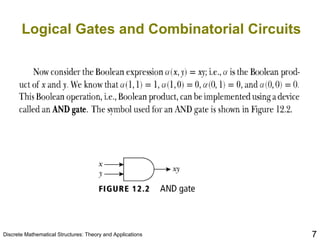
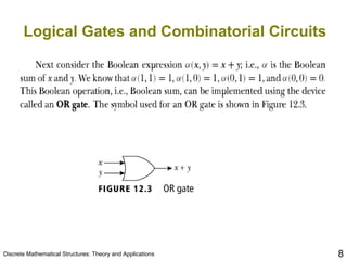
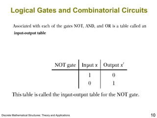

The document discusses Boolean algebra and its applications in electronic circuits. It covers learning objectives around Boolean expressions, properties of Boolean algebra, and using Boolean algebra in switching circuits and logical gates. The basic gates are introduced as NOT, AND, and OR, and it is explained that any combinatorial circuit can be designed using combinations of these gates, where the output depends only on the current inputs.