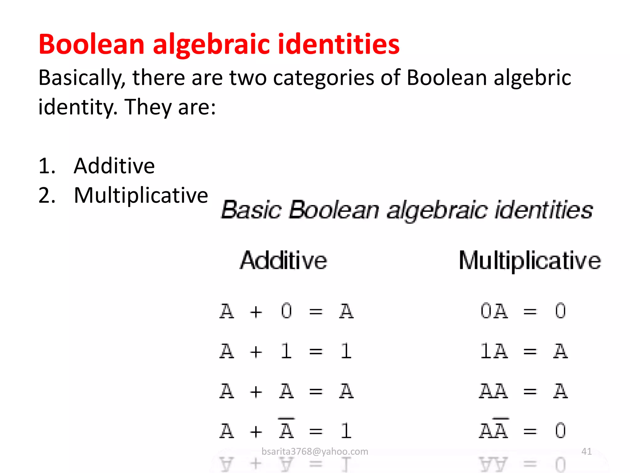
Download to read offline
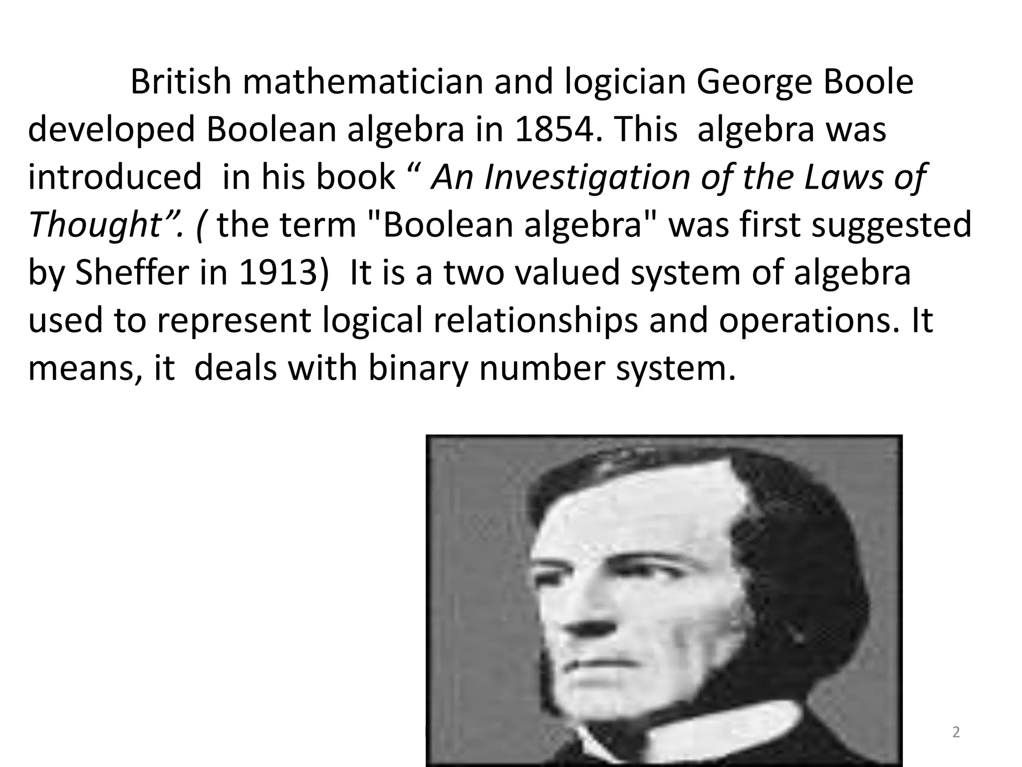

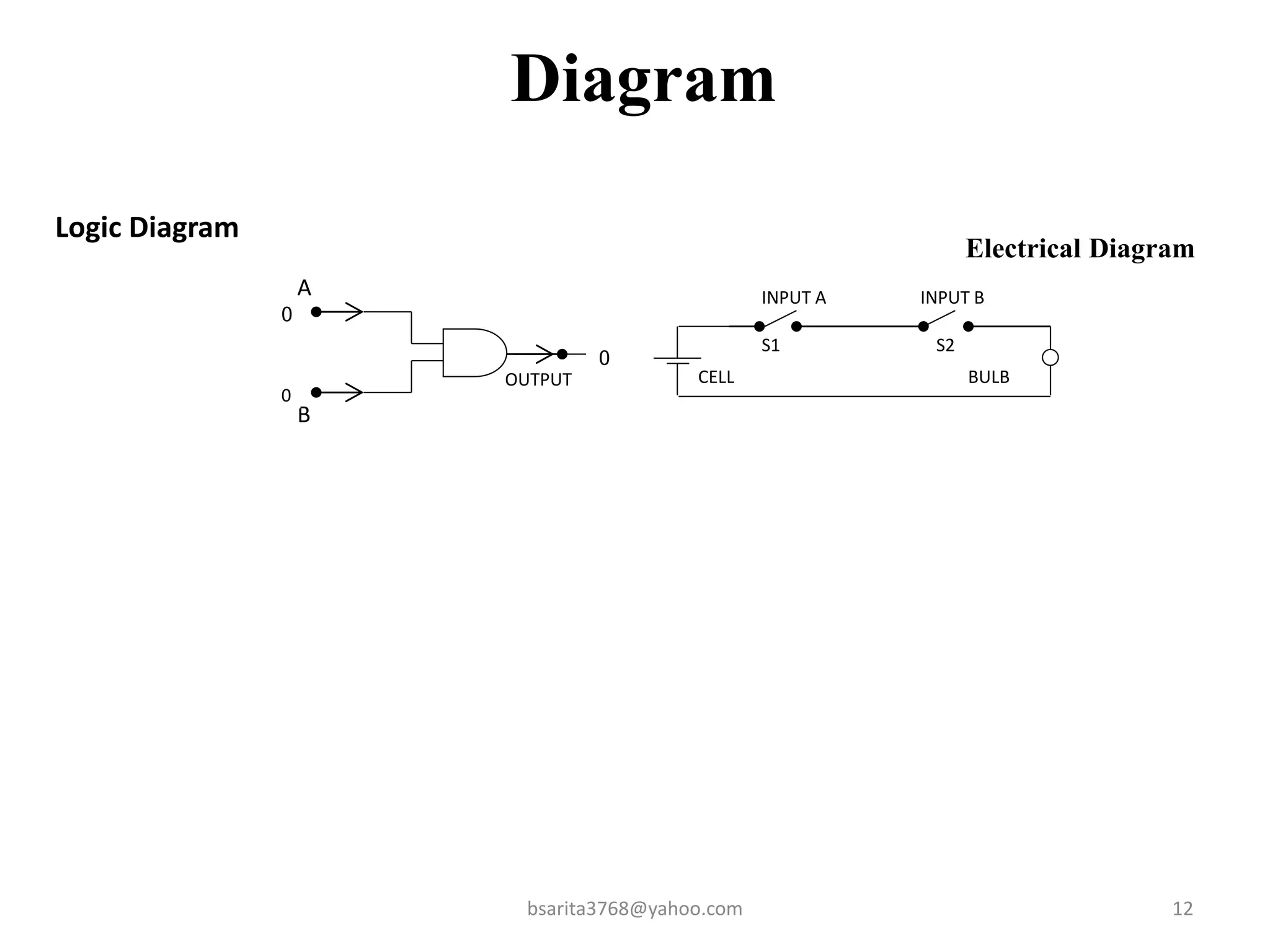
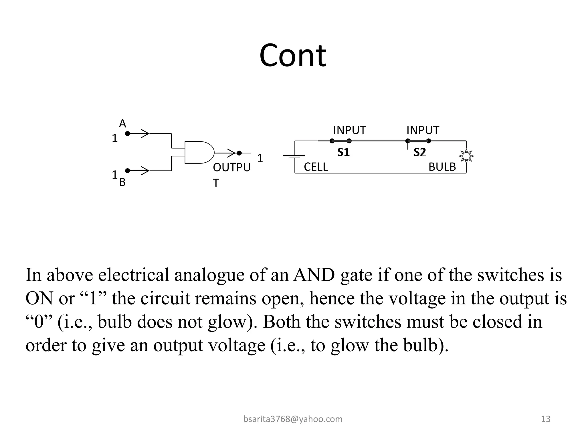
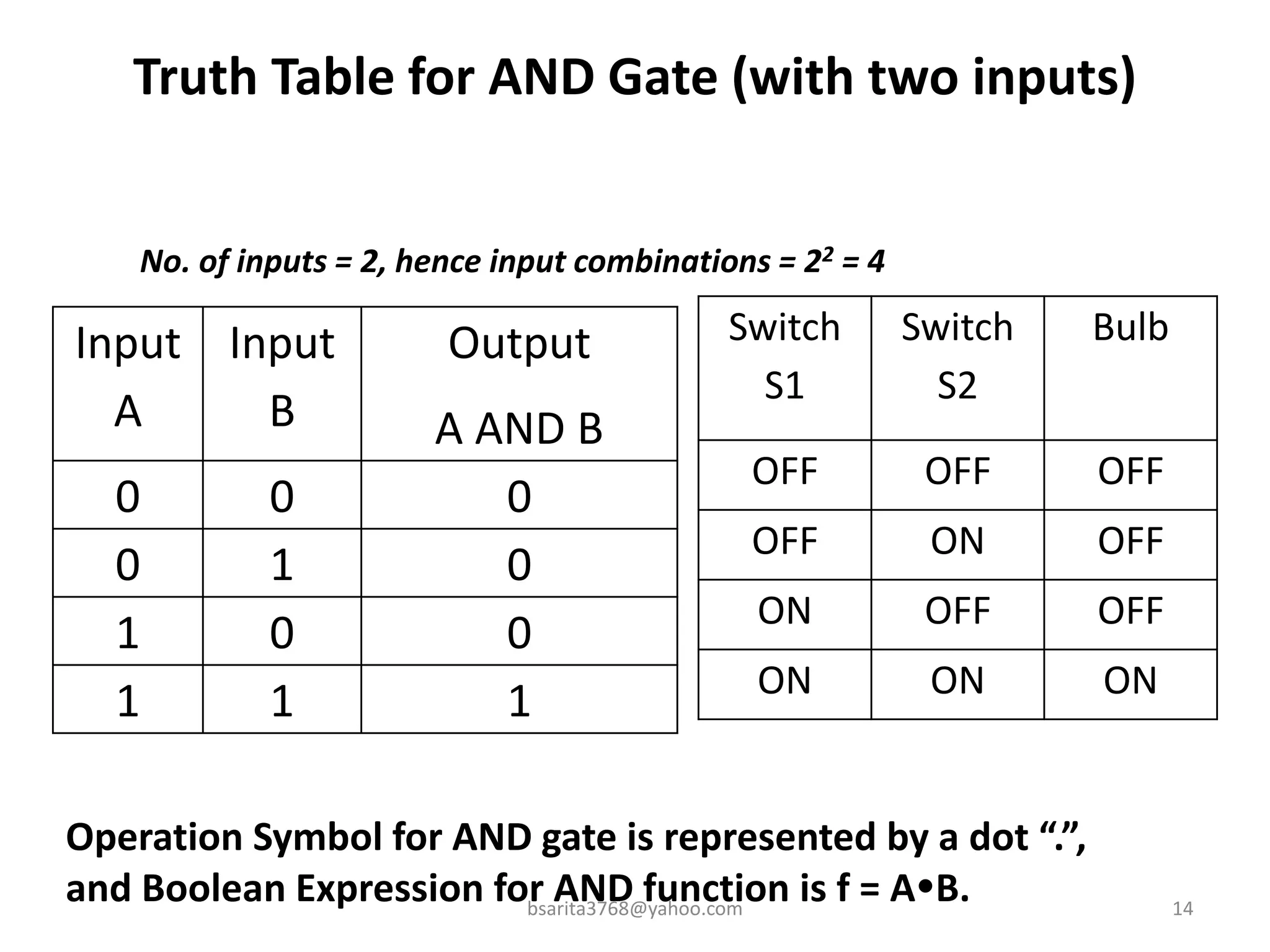
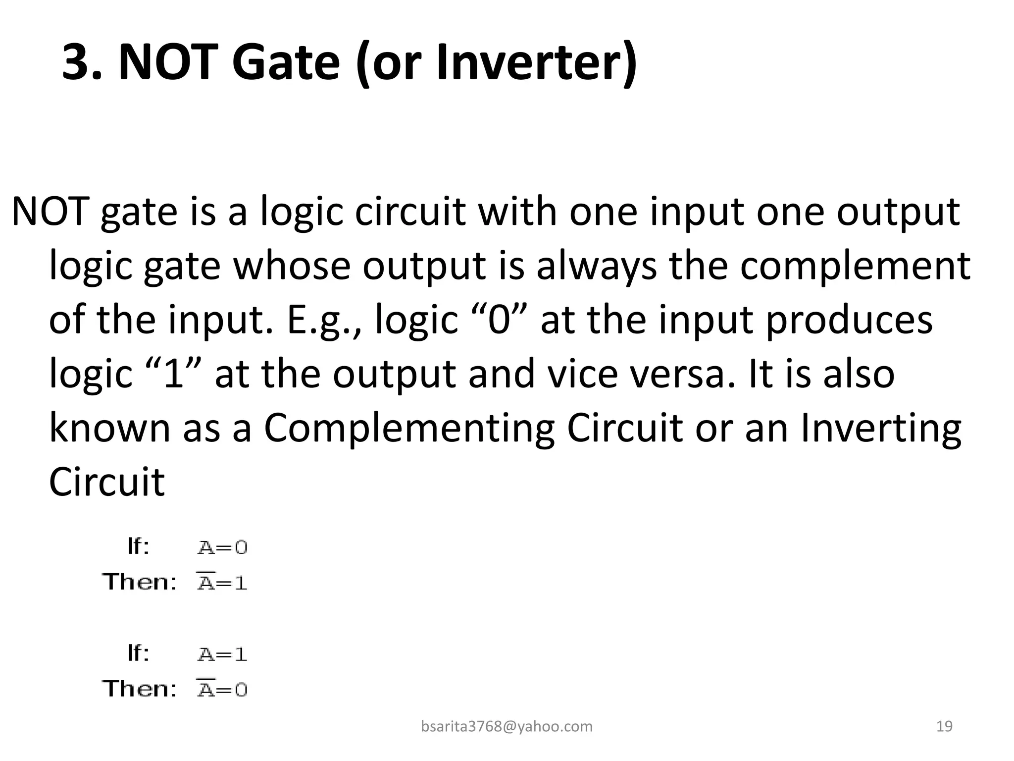
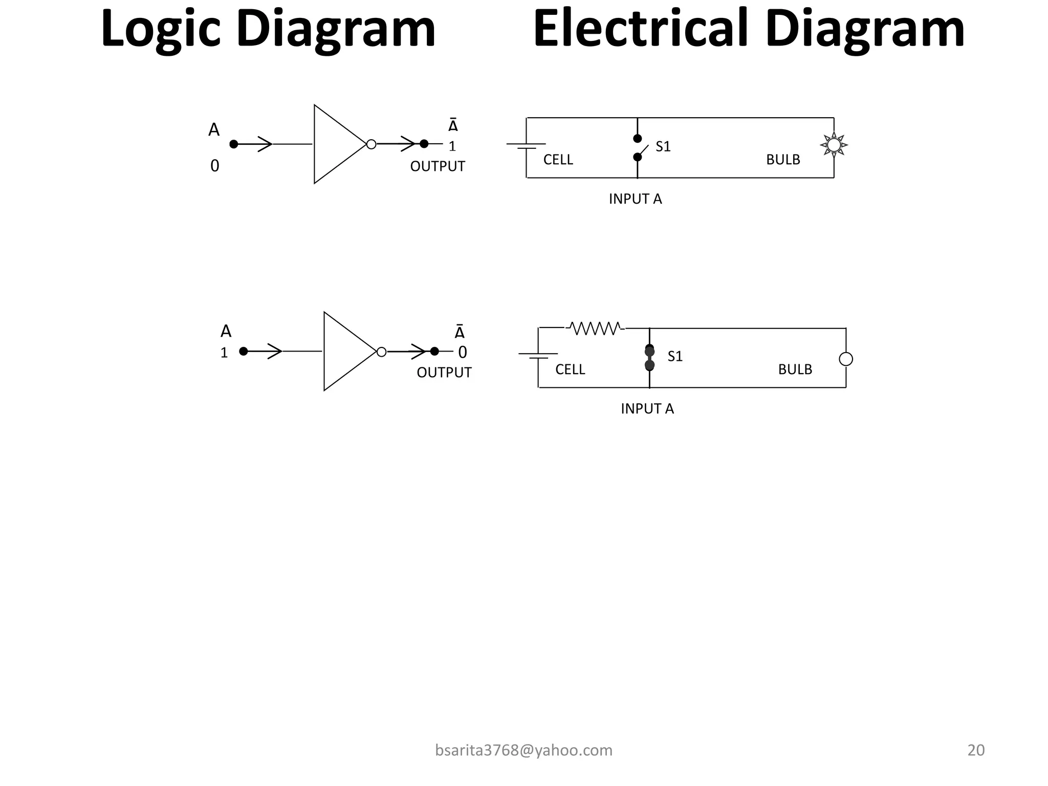
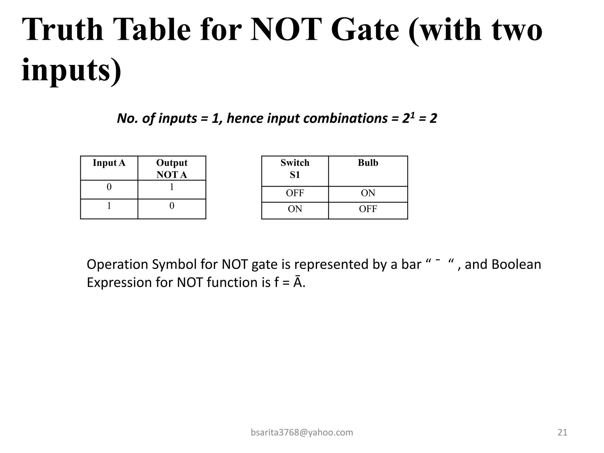
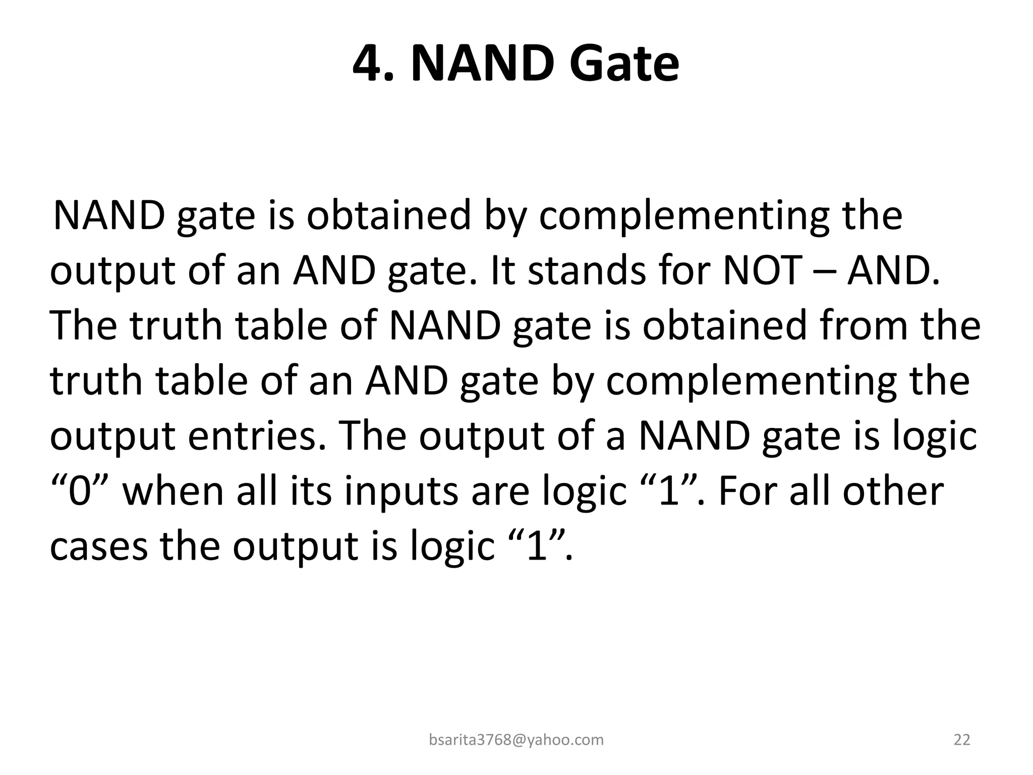
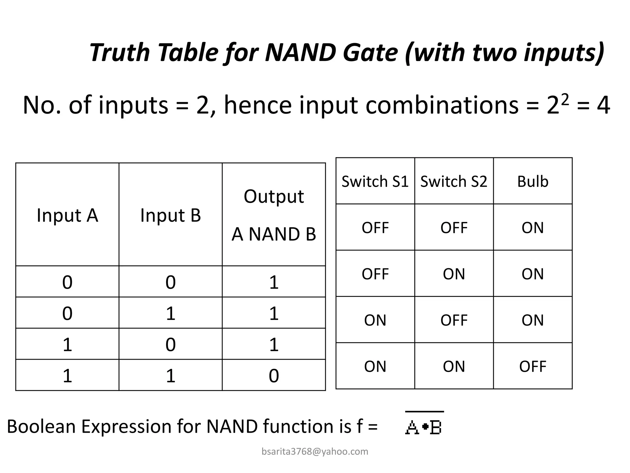
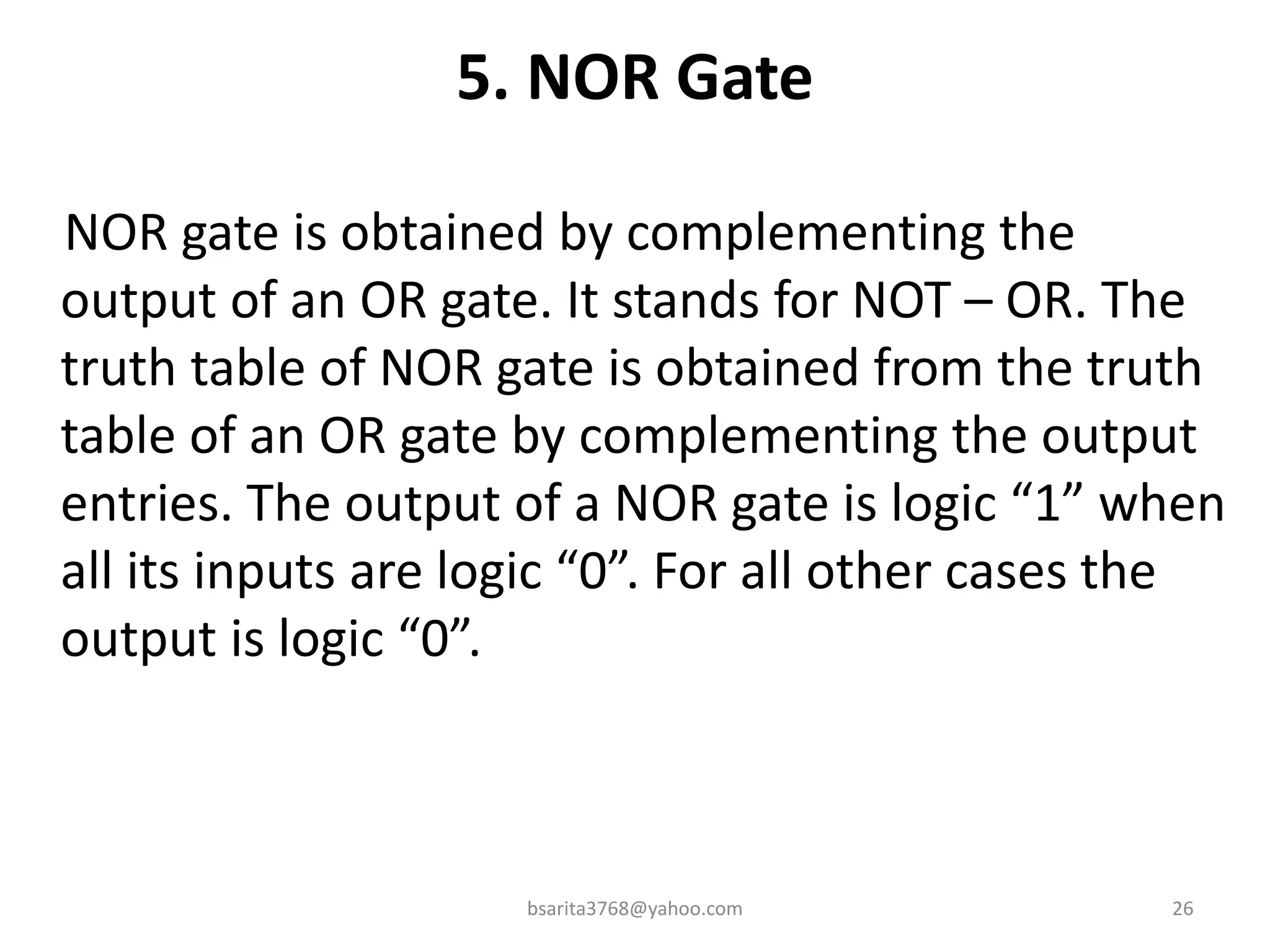
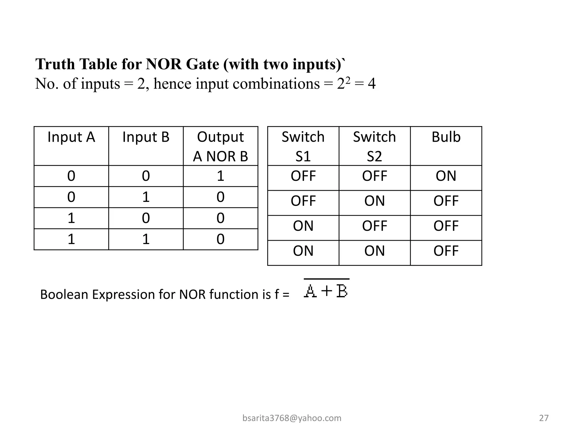
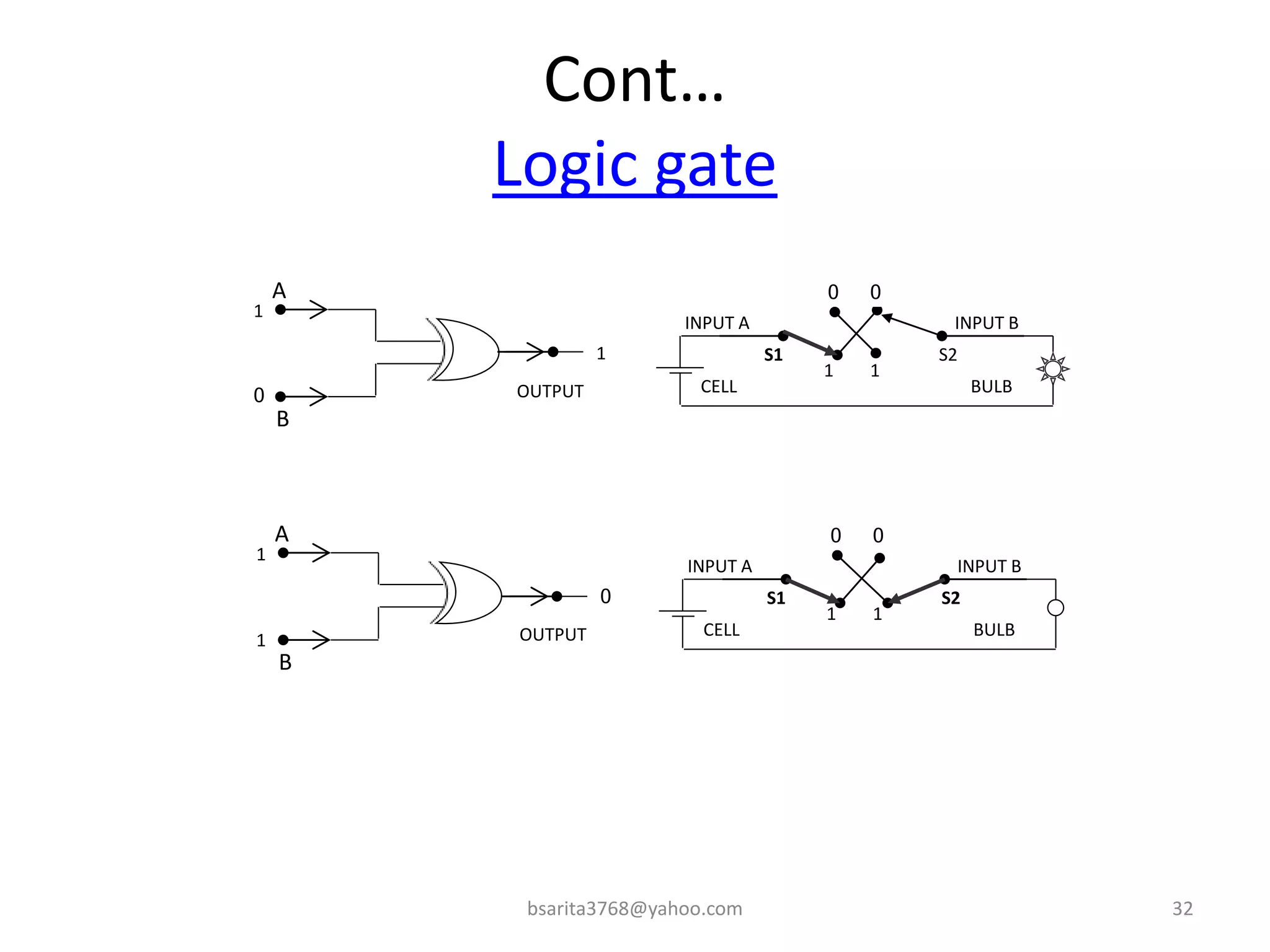
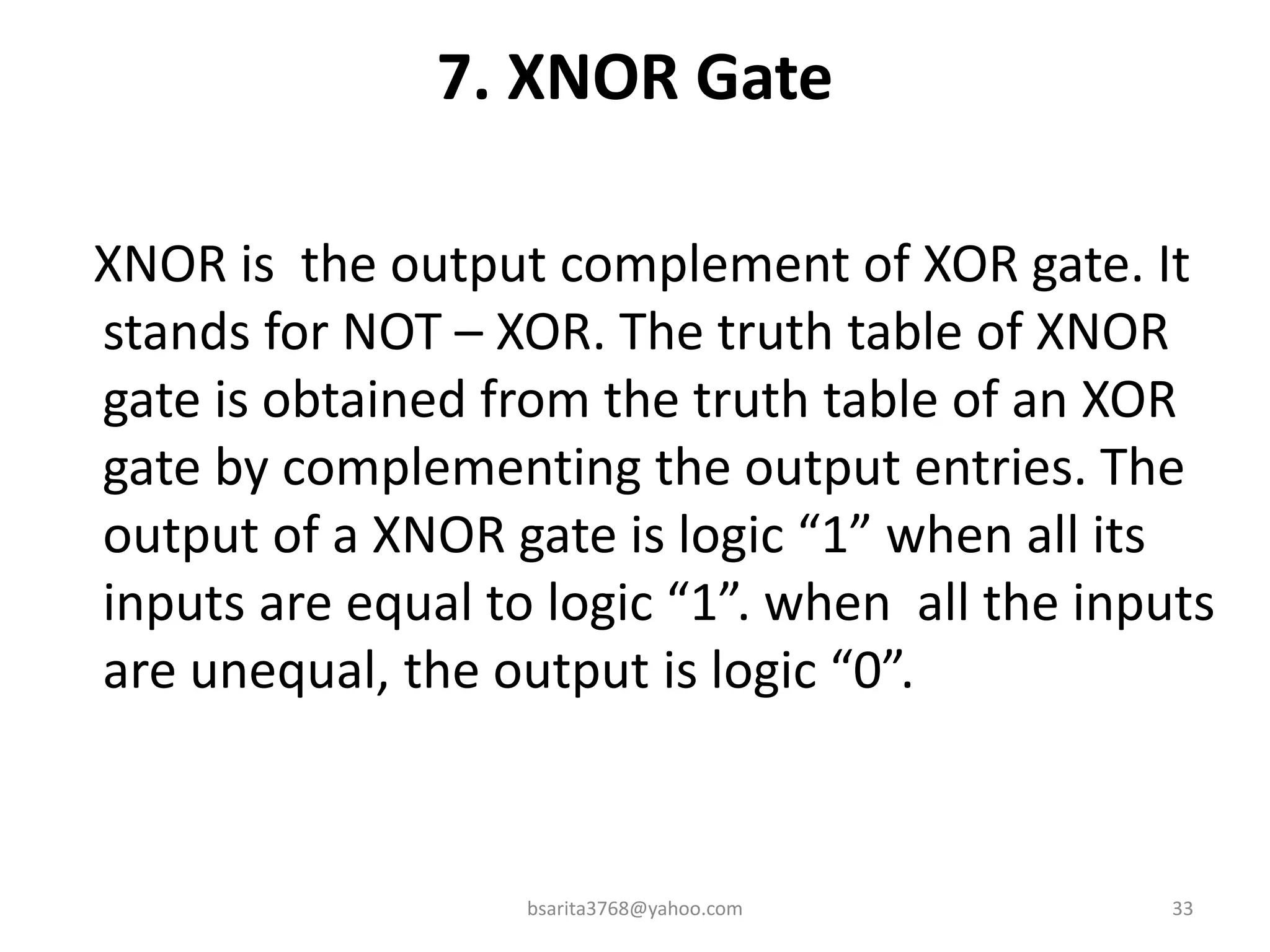
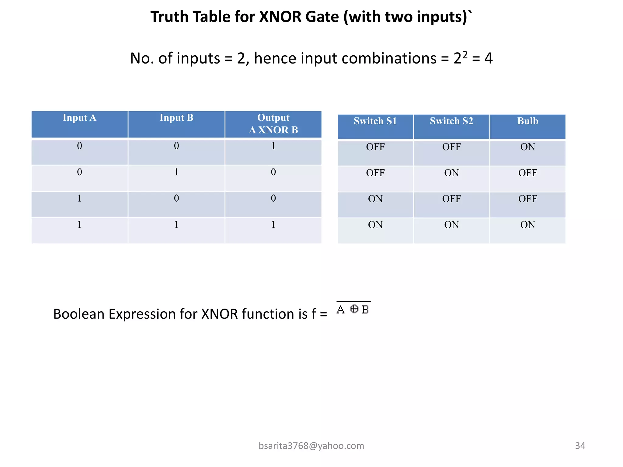
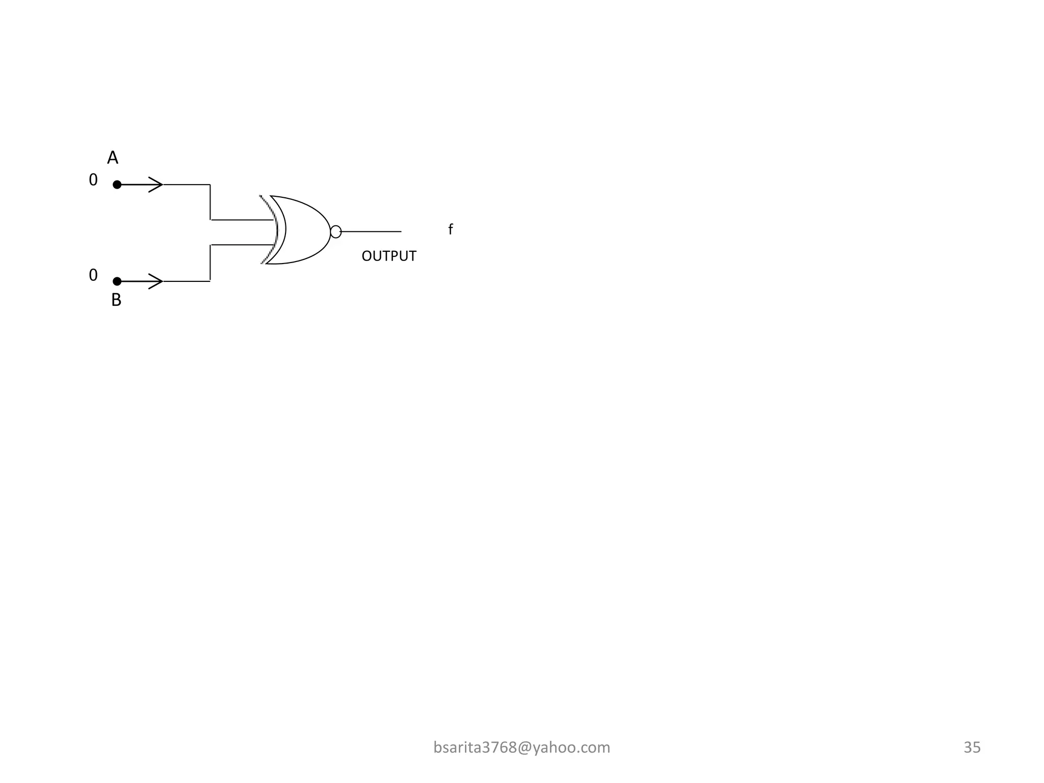

Boolean algebra is a two-valued system used for representing logical relationships, developed by George Boole in 1854. It serves as the foundation for digital logic, involving operations like AND, OR, and NOT, which are essential for designing logic circuits in digital electronics. The document also explains various logic gates and their functions, including AND, OR, NOT, NAND, NOR, XOR, and XNOR, along with truth tables and boolean algebraic identities.


![Chapter 3 computer Boolean Algebra 2[1].pptx](https://cdn.slidesharecdn.com/ss_thumbnails/chapter3booleanalgebra21-240928031107-5861eb7e-thumbnail.jpg?width=640&height=640&fit=bounds)