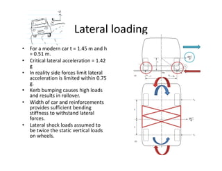
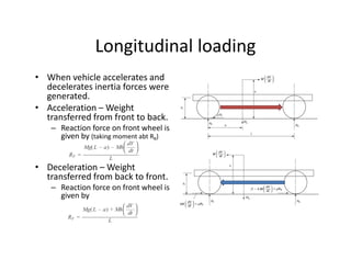
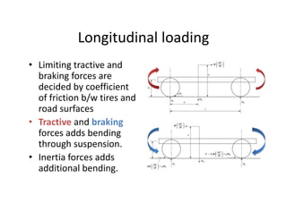
IntroductionIntroduction
• Loads due to normal running conditions:Loads due to normal running conditions:
– Vehicle transverse on uneven ground.
– Manoeuver performed by driver.p y
• Five basic load cases:
– Bending caseBending case
– Torsion case
– Combined bending and torsiong
– Lateral loading 
– Fore and aft loadingg
Bending PayloadBending
• Due to loading in  Engine
Occupants
Fuel tank
Payload
vertical (X‐Z) plane.
• Due to weight of 
components along
Engine
components along 
the vehicle frame.
• Static condition vehicle  Wheels/ 
b ki
Suspension
structure can be treated 
as 2‐D beam.
– Vehicle is approximately symmetric in x‐y plane.
braking
pp y y y p
• Unsprung mass
– Components lie below chassis
– Do not impose loads in static conditionDo not impose loads in static condition.
Bending moment/ Shear force diagram of a typical 
hi lpassenger vehicle
BendingBending
• Dynamic loading:
– Inertia of the structure contributes in total loading
– Always higher than static loading
– Road vehicles: 2.5 to 3 times static loads
– Off road vehicles: 4 times static loads
E l• Example:
– Static loads
• Vehicle at rest .
• Moving at a constant velocity on a even road.
m
g
Moving at a constant velocity on a even road.
• Can be solved using static equilibrium balance.
• Results in set of algebraic equations.
– Dynamic loads
V hi l i b d t t t l it
F
• Vehicle moving on a bumpy road even at  constant velocity.
• Can be solved using dynamic equilibrium balance.
• Generally results in differential equations.
m
g
m
a
F
TorsionTorsion
• When vehicle traverse on an 
d luneven road.
• Front and rear axles 
experiences a moment.
• Pure simple torsion:
Front axle
Rear axle
• Pure simple torsion:
– Torque is applied to one axle 
and reacted by other axle.
– Front axle: anti clockwise 
torque (front view)
– Rear axle: balances with 
clockwise torque 
– Results in a torsion momentResults in a torsion moment 
about x‐ axis.
• In reality torsion is always 
accompanied by bending due 
t itto gravity.
TorsionTorsion
l
Front axle
Rear axle
Combined bending and torsionCombined bending and torsion
• Bending and torsional loads are super 
imposed.imposed.
– Loadings are assumed to be linear 
• One wheel of the lightly loaded axle is raised 
on a bump result in the other wheel go off 
ground.
• All loads of lighter axle is applied to one Bending Torsion• All loads of lighter axle is applied to one 
wheel.
• Due to nature of resulting loads, loading 
symmetry wrt x‐z plane is lost.
• R’R can be determined from moment 
balance
g
balance.
• R’R stabilizes the structure by increasing the 
reaction force on the side where the wheel is 
off ground .
• The marked –
– Side is off ground
– Side takes all load of front axle
– Side’s reaction force increases
– Side’s reaction force decreases 
to balance the moment.
Combined bending and torsion
Lateral loadingLateral loading
• For a modern car t = 1.45 m and h 
0 51 m= 0.51 m. 
• Critical lateral acceleration = 1.42 
g
• In reality side forces limit lateral y
acceleration is limited within 0.75 
g.
• Kerb bumping causes high loads 
and results in rolloverand results in rollover.
• Width of car and reinforcements 
provides sufficient bending 
stiffness to withstand lateral 
forcesforces.
• Lateral shock loads assumed to 
be twice the static vertical loads 
on wheels.
Longitudinal loadingLongitudinal loading
• When vehicle accelerates and 
d l t i ti fdecelerates inertia forces were 
generated.
• Acceleration – Weight 
transferred from front to backtransferred from front to back.
– Reaction force on front wheel is 
given by (taking moment abt RR)
• Deceleration – Weight 
transferred from back to front.
Reaction force on front wheel is– Reaction force on front wheel is 
given by
Longitudinal loadingLongitudinal loading
• Limiting tractive and g
braking forces are 
decided by coefficient 
of friction b/w tires andof friction b/w tires and 
road surfaces
• Tractive and brakingTractive and braking
forces adds bending 
through suspension.
• Inertia forces adds 
additional bending.
Asymmetric loadingAsymmetric loading  
• Results when one wheel strikes a 
raised objects or drops into a pit.
• Resolved as vertical and horizontal loads.
• Magnitude of force depends on• Magnitude of force depends on 
– Speed of vehicle
– Suspension stiffness
Wheel mass
Raised 
object`
– Wheel mass
– Body mass
• Applied load is a shock wave
h h h l d– Which has very less time duration
– Hence there is no change in vehicle speed
– Acts through the center of the wheel.
Asymmetric loadingAsymmetric loading
• Resolved vertical force causes:
– Additional axle load
– Vertical inertia load through CG
– Torsion moment
to maintain dynamic equilibriumto maintain dynamic equilibrium.
• Resolved horizontal force 
causes:
– Bending in x‐z planeBending in x z plane
– Horizontal inertia load through 
CG
– Moment about z axis
to maintain dynamic equilibrium.
• Total loading is the 
superposition of all four loads.

Loads acting on frame

  • 1.
    IntroductionIntroduction • Loads dueto normal running conditions:Loads due to normal running conditions: – Vehicle transverse on uneven ground. – Manoeuver performed by driver.p y • Five basic load cases: – Bending caseBending case – Torsion case – Combined bending and torsiong – Lateral loading  – Fore and aft loadingg
  • 2.
    Bending PayloadBending • Due to loading in Engine Occupants Fuel tank Payload vertical (X‐Z) plane. • Due to weight of  components along Engine components along  the vehicle frame. • Static condition vehicle  Wheels/  b ki Suspension structure can be treated  as 2‐D beam. – Vehicle is approximately symmetric in x‐y plane. braking pp y y y p • Unsprung mass – Components lie below chassis – Do not impose loads in static conditionDo not impose loads in static condition.
  • 3.
  • 4.
    BendingBending • Dynamic loading: – Inertia of the structure contributes in total loading –Always higher than static loading – Road vehicles: 2.5 to 3 times static loads – Off road vehicles: 4 times static loads E l• Example: – Static loads • Vehicle at rest . • Moving at a constant velocity on a even road. m g Moving at a constant velocity on a even road. • Can be solved using static equilibrium balance. • Results in set of algebraic equations. – Dynamic loads V hi l i b d t t t l it F • Vehicle moving on a bumpy road even at  constant velocity. • Can be solved using dynamic equilibrium balance. • Generally results in differential equations. m g m a F
  • 5.
    TorsionTorsion • When vehicle traverse on an  d luneven road. •Front and rear axles  experiences a moment. • Pure simple torsion: Front axle Rear axle • Pure simple torsion: – Torque is applied to one axle  and reacted by other axle. – Front axle: anti clockwise  torque (front view) – Rear axle: balances with  clockwise torque  – Results in a torsion momentResults in a torsion moment  about x‐ axis. • In reality torsion is always  accompanied by bending due  t itto gravity.
  • 6.
  • 7.
    Combined bending andtorsionCombined bending and torsion • Bending and torsional loads are super  imposed.imposed. – Loadings are assumed to be linear  • One wheel of the lightly loaded axle is raised  on a bump result in the other wheel go off  ground. • All loads of lighter axle is applied to one Bending Torsion• All loads of lighter axle is applied to one  wheel. • Due to nature of resulting loads, loading  symmetry wrt x‐z plane is lost. • R’R can be determined from moment  balance g balance. • R’R stabilizes the structure by increasing the  reaction force on the side where the wheel is  off ground . • The marked – – Side is off ground – Side takes all load of front axle – Side’s reaction force increases – Side’s reaction force decreases  to balance the moment. Combined bending and torsion
  • 8.
  • 9.
    Lateral loadingLateral loading • For a modern car t = 1.45 m and h  051 m= 0.51 m.  • Critical lateral acceleration = 1.42  g • In reality side forces limit lateral y acceleration is limited within 0.75  g. • Kerb bumping causes high loads  and results in rolloverand results in rollover. • Width of car and reinforcements  provides sufficient bending  stiffness to withstand lateral  forcesforces. • Lateral shock loads assumed to  be twice the static vertical loads  on wheels.
  • 10.
    Longitudinal loadingLongitudinal loading • When vehicle accelerates and  dl t i ti fdecelerates inertia forces were  generated. • Acceleration – Weight  transferred from front to backtransferred from front to back. – Reaction force on front wheel is  given by (taking moment abt RR) • Deceleration – Weight  transferred from back to front. Reaction force on front wheel is– Reaction force on front wheel is  given by
  • 11.
    Longitudinal loadingLongitudinal loading • Limiting tractive and g braking forces are  decided by coefficient  offriction b/w tires andof friction b/w tires and  road surfaces • Tractive and brakingTractive and braking forces adds bending  through suspension. • Inertia forces adds  additional bending.
  • 12.
    Asymmetric loadingAsymmetric loading   • Results when one wheel strikes a  raised objects or drops into a pit. •Resolved as vertical and horizontal loads. • Magnitude of force depends on• Magnitude of force depends on  – Speed of vehicle – Suspension stiffness Wheel mass Raised  object` – Wheel mass – Body mass • Applied load is a shock wave h h h l d– Which has very less time duration – Hence there is no change in vehicle speed – Acts through the center of the wheel.
  • 13.
    Asymmetric loadingAsymmetric loading • Resolved vertical force causes: –Additional axle load – Vertical inertia load through CG – Torsion moment to maintain dynamic equilibriumto maintain dynamic equilibrium. • Resolved horizontal force  causes: – Bending in x‐z planeBending in x z plane – Horizontal inertia load through  CG – Moment about z axis to maintain dynamic equilibrium. • Total loading is the  superposition of all four loads.