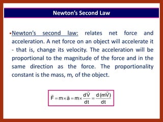
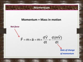
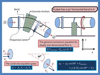
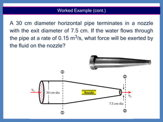
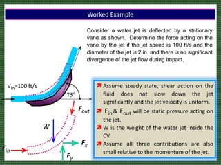
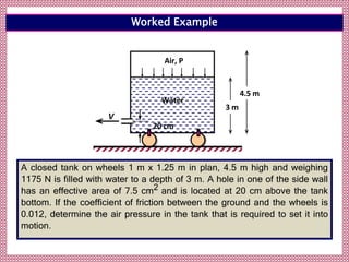
Minia University
‫ـــعة‬‫م‬‫جا‬
‫يا‬‫ن‬‫مل‬‫ا‬
LINEAR MOMENTUM EQUATION
BY:
Dr. Ezzat El-sayed G. SALEH
«
‫يل‬‫مجل‬‫ا‬ ‫ناكر‬‫ا‬
.......
‫عصاه‬ ‫معي‬‫أ‬‫ل‬‫ا‬ ‫رس‬‫يك‬ ‫ن‬‫أ‬‫أ‬
........
‫نع‬‫ي‬ ‫ن‬‫أ‬‫أ‬ ‫بعد‬
‫هللا‬ ‫م‬
‫بصار‬‫ال‬ ‫بعودة‬ ‫يه‬‫عل‬
»
..
Newton’s Laws of Motion
 Newton’s 2nd and 3rd Laws
 Conservation of Momentum
 Linear Momentum Equation
 General form of equation
 Sample Applications
 Momentum Correction Factor
Topic Covered
•Newton’s second law: relates net force and
acceleration. A net force on an object will accelerate it
- that is, change its velocity. The acceleration will be
proportional to the magnitude of the force and in the
same direction as the force. The proportionality
constant is the mass, m, of the object.
t
d
)
V
m
(
d
t
d
V
d
m
a
m
F









Newton’s Second Law
t
d
)
V
m
(
d
t
d
V
d
m
a
m
F









Net force
Rate of change
of momentum
Momentum = Mass in motion
Momentum
Friction is Caused by:
Friction is caused by:
 The irregularities in the surfaces in mutual contact (Mutual
=‫تبادل‬‫م‬) , and
 Depends on the kinds of material, and
 How much they are pressed together.
Newton's First law of motion can be formally stated as follows:
An object at rest stays at rest and an object in motion stays in motion
with the same speed and in the same direction unless acted upon by an
unbalanced force.
Newton's second law of motion can be formally stated as follows:
The acceleration of an object as produced by a net force is directly
proportional to the magnitude of the net force, in the same direction as
the net force, and inversely proportional to the mass of the object.
Fnet = m • a
Newton's law of motion is often stated as:
Consistent with the above equation, a unit of force is equal to a unit of
mass times a unit of acceleration. By substituting standard metric units
for force, mass, and acceleration into the above equation, the following
unit equivalency can be written.
1 Newton = 1 kg • m/s2
The third law states that for every action (force) in nature there is an
equal and opposite reaction. In other words, if object “A” exerts a force
on object “B”, then object B also exerts an equal force on object A. Notice
that the forces are exerted on different objects.
a) With more force when the rope is attached to the wall.
b) With more force when the rope is attached to the elephant.
c) The same force in each case.
Momentum
Momentum measures the strength of
an object’s motion.
Momentum (M) depends on an object’s
mass and its velocity.
 More mass = more momentum
 More velocity = more momentum
Momentum
Momentum (p) = mass x velocity
p = mv
Momentum is a vector quantity!
Momentum acts in the same direction
as the velocity.
Unit = kg. m/s
Do not confuse with a Newton
Impulse and Changing Momentum
To change the momentum a force is
required but is not the only factor in
changing momentum
To change the momentum an Impulse is
required.
Impulse is the product of the Applied Force
and the time Interval in which the force acts.
Impulse and Changing Momentum
Impulse = F. dt
Impulse is a vector quantity (it is in the same
direction as the force).
Unit = N. s or kg. m/s (same as momentum)
How can we have a Large Impulse?
To Have a Large Impulse
1) Large Force over a small time interval,
2) Small Force over a large time interval.
Impulse = F. Dt
Impulse-Momentum Theorem
An Impulse causes a change in momentum.
(If the mass remains constant then the
velocity of the object must change.)
F. Dt = D p = m. Dv
Note: Another way of expressing Newton’s 2nd
Law
Conservation of Momentum
 Newton’s 3rd Law applies to momentum
as well as forces.
 Momentum will be conserved in
collisions (
‫صطدام‬‫ا‬
) .
–Conservation means the total amount
remains constant!
Wind Turbine Hydropower Turbine
The motion of a fluid is altered so that propulsive forces (
‫قوي‬
‫ادلفع‬
) can be
generated on the devices. The integral linear momentum equation is used
to determine the forces acting on such devices. Other examples: lift and
drag forces on wings, pressure surge across a compressor.
Practical Applications
Slide Gate (Nepal)
 (2)
Sluice Gate Geometry
Sluice gate of width “W”
 (1)
y1
y2
HGL
EGL
yG
Sluice gate are often used to
regulate and measure the
flowrate in open channel
yG is the gate
opening
 (1)
Hydraulic Jump
o= 0
V1
V2
F1
F2
y1
y2
C.V
C D L
E
S
(1)
E
S
(2)
EL

 

E G L
V2
2/2g
V1
2/2g
A control volume is chosen such that the hydraulic jump
is enclosed at the upstream and downstream boundaries,
where the flow is nearly parallel
 Newton’s third law of motion: states that an
object experiences a force because it is
interacting with some other object.
Newton Third Law
 The force that object  exerts on object  must be
of the same magnitude but in the opposite direction
as the force that object  exerts on object .
Baseball Tennis
Bowling Soccer
Karate
Foot ball
Momentum
 All objects have mass; so if an object is moving, then it
has momentum - it has its mass in motion.
 The amount of momentum which an object has is
dependent upon two variables:
How much matter is moving?
How fast the matter is moving?
‫ادلفع‬ ‫قوة‬ = Momentum
• Is momentum a vector quantity? ? ?
The direction of the
momentum vector is the
same as the direction of
the velocity vector
Momentum
 Newton’s third law also requires the
conservation of momentum, or the product of
mass and velocity.
Conservation of Momentum (Linear)
 For an isolated system, with no external forces
acting on it, the momentum must remain
constant.
• The angular momentum of a rotating object depends on its
speed of rotation, its mass, and the distance of the mass
from the axis.
Conservation of Angular (rotational) Momentum
• When a skater standing on a friction-free point spins faster
and faster, angular momentum is conserved despite the
increasing speed.
• At the start of the spin, the skater’s arms are outstretched.
Part of the mass is therefore at a large radius. As the
skater’s arms are lowered, thus decreasing their distance
from the axis of rotation, the rotational speed must
increase in order to maintain constant angular momentum.
• Momentum Equation states that the vector sum of all
external forces acting on a control volume in a fluid flow
equals the time rate of change of linear momentum
vector of the fluid mass in the control volume.
Linear Momentum Equation
• A control volume is defined as a volume fixed in space.
In the application of the linear momentum equation the control volume
can be assumed arbitrarily. It is usual practice to draw a control
volume in such away that:
Its boundaries are normal to the direction of flow at outlets and
inlets,
It is inside the flow boundary and has the same alignment as the
flow boundary,
Whenever the magnitude of the boundary forces (due to pressure
and shear stresses) are not known, their resultant is taken as a
reaction force “R” (with components, Rx, Ry, and Rz) on the control
volume. This reaction R is the force acting on the fluid in the
control volume due to reaction from the boundary. The force “F” on
the boundary will be equal and opposite to the reaction “R”.
Control Volume
40
• Linear Momentum Equation in general form
  in
out x
x
CV
x
bx
sx
px
)
system
(
x M
M
M
t
F
F
F
F 








Linear Momentum Equation
• Where Fpx, Fsx and Fbx represent x- component of pressure force,
shear force and body force (weight) respectively acting on CV
• Mx is moment flux in x-direction =  Q Vx. Suffix out represent
flux going out of the CV and in for flux entering the CV.
• First right hand term is rate of change of momentum within CV.
The momentum equation may be used directly to
evaluate the force causing a change of momentum in a
fluid:
Applications :determining forces on:
• Pipe bends,
•Junctions,
•Nozzles, and
•Hydraulic machines.
Linear Momentum Equation
In addition, the momentum equation is used directly to
evaluate and solve problems in which energy losses
occur that cannot be evaluated directly, or when the flow
is unsteady
Examples of such problems include:
•Local head losses in pipes,
•The hydraulic jump, and
•Unsteady flow in pipes and channels.
Linear Momentum Equation
Expansion Joints
Concrete Anchors
Bend
30o

P1
P
2
V1
V2
y
x
The general momentum equation for
steady one-dimensional flow is:
30o
The continuity equation gives:
A pipe has a 30o horizontal bend in it
450




30 cm-
dia. pipe
V2 cos
V2 sin
FX
Fy
V1

X
y
P1
P2
A 30 cm diameter pipe carries water under a head of 20 m
with a velocity of 3.5 m/s. If the axis of the pipe turns
through 45o, find the magnitude and direction of the
resultant force on the bend. Neglect friction forces.
Worked Example
450




30 cm-
dia. pipe
V2 cos
V2 sin
FX
Fy
V1

X
y
P1
P2
Worked Example (cont.)
s
/
m
247
.
0
5
.
3
0707
.
0
V
A
Q
discharge
the
and
,
m
0707
.
0
3
.
0
)
4
(
A
A
area
sectional
-
cross
The
3
1
1
2
2
2
1








 
 Since the pipe is of uniform cross section therefore,
s
/
m
5
.
3
V
V 2
1 

 Neglecting change in elevation and head loss
2
3
3
2
1 m
/
N
2
.
196
10
20
81
.
9
10
h
g
p
p 





 













N
8
.
10419
45
sin
0707
.
0
2
.
196
10
45
sin
5
.
3
247
.
0
10
F
)
0
45
sin
V
(
Q
45
sin
A
p
0
F
0
3
0
3
y
0
2
0
2
2
y 
kN
11.278
1000
11278.3
8
.
10419
4316
F
F
F 2
2
2
y
2
x
R 






'
o
x
y
28
67
41
.
2
F
F
tan
and 

 

 Similarly, force along y-axis
 Magnitude of resultant force
 Force along X-axis
















N
4316
)
1
45
(cos
5
.
3
247
.
0
10
)
45
cos
1
(
0707
.
0
2
.
196
10
F
)
V
45
cos
V
(
Q
45
cos
A
p
A
p
F
o
3
o
3
x
1
0
2
0
2
2
1
1
x 


Worked Example (cont.)
Control Surface




The continuity equation gives:
The general momentum equation
for steady one-dimensional flow
is: x
y
P1
V1 V2
P2
)
V
V
(
Q
F
p
p
1
2
b o ld
2
1





A Fitting between Two Pipes of Different Size (TRANSITION)
7.5 cm-dia
Nozzle




V1
V2
30 cm-dia
A 30 cm diameter horizontal pipe terminates in a nozzle
with the exit diameter of 7.5 cm. If the water flows through
the pipe at a rate of 0.15 m3/s, what force will be exerted by
the fluid on the nozzle?
Worked Example (cont.)
 Flow velocity at inlet and exit may be determined using the
continuity equation
s
/
m
12
.
2
4
/
3
.
0
15
.
0
V 2
1 



g
2
V
g
p
Z
g
2
V
g
p
Z
2
2
2
2
2
1
1
1 






s
/
m
95
.
33
4
/
075
.
0
15
.
0
V 2
2 



2
1 m
/
kN
05
.
574
p
or 
Since, the pipe is horizontal (Z1 = Z2) and p2 = patm = 0 (gage)
g
2
V
g
2
V
g
p 2
1
2
2
1



 The pressure p1 may be found by applying Bernoulli’s equation
between points “1” and “2”
Worked Example (cont.)
 Nozzle will exert a force of 35.80 kN in negative X–direction
and water would exert equal force in +ve X- direction.
 
kN
80
.
35
78
.
4
58
.
40
F
or
V
V
Q
A
p
F
nozzle
1
2
1
1
nozzle









Where all terms are taken positive with x- axis
 Equating change in momentum to forces in x-direction (p2= 0
and neglecting friction)
Worked Example (cont.)
Consider a water jet is deflected by a stationary
vane as shown. Determine the force acting on the
vane by the jet if the jet speed is 100 ft/s and the
diameter of the jet is 2 in. and there is no significant
divergence of the jet flow during impact.
75°
Vin=100 ft/s
Fin
Fout
Fx
Fy
 Assume steady state, shear action on the
fluid does not slow down the jet
significantly and the jet velocity is uniform.
 Fin & Fout will be static pressure acting on
the jet.
 W is the weight of the water jet inside the
CV.
 Assume all three contributions are also
small relative to the momentum of the jet.
W
Worked Example
The only body force is the weight of the jet, and is considered
negligible, . There are surface forces on all sides of the cv,
however, contributions from three sides are also small.
Therefore, only the surface forces acting on the jet by the vane
are considered. These forces include the pressure force and the
shear force and the sum of these forces is equal to R with
components of RX and Ry in the X- and y-direction, respectively.
0
FE 

Therefore, the linear momentum equation can be written as:
Worked Example (cont.)
 
f
o
2
in
out
x
Ib
7
.
313
100
75
cos
100
100
12
1
94
.
1
)
V
V
(
Q
F























 

 
f
o
2
in
out
y
Ib
8
.
408
0
75
sin
100
100
12
1
94
.
1
)
V
V
(
Q
F






















 

 Force along X-axis
 Similarly, force along y-axis
 The forces on the vane are:
right
the
to
acting
Ib
7
.
313
F
R f
x
x 



downward
acting
Ib
8
.
408
F
R f
y
y 





Worked Example (cont.)
A closed tank on wheels 1 m x 1.25 m in plan, 4.5 m high and weighing
1175 N is filled with water to a depth of 3 m. A hole in one of the side wall
has an effective area of 7.5 cm2 and is located at 20 cm above the tank
bottom. If the coefficient of friction between the ground and the wheels is
0.012, determine the air pressure in the tank that is required to set it into
motion.
Air, P
3 m
4.5 m
V
20 cm
Water
Worked Example
 Total weight of the system
W = 1175 + 1000x9.81x(1x1.25x3) = 37962 N 
 Force required to move the tank
F =  W = 0.012 x 37962 = 455.5 N 
 Change in momentum required
455.5 =  Q (V2 - V1) =  V2
2 A2 …………… (1)
V2 : velocity of jet leaving tank,
V1 : Velocity of tank water and can be taken as practically  0.
Since A2 = 7.510-4 m2 and w = 1000 kg/m3, Eq. (1) gives
Worked Example (cont.)
FX
Air, P
3 m
4.5 m
V2
20 cm
Water
A
 Applying Bernoulli’s Equation between points “A” and “2” gives
  water
of
m
14
.
28
)
3
2
.
0
(
81
.
9
x
2
64
.
24
z
z
g
2
V
g
p 2
A
2
2
2
A








 V2 = 24.64 m/s.
Reference datum
From the attached
figure,
Z1 = 3m, Z2 = 0.20m,
p2 = patm. = 0
pA = ?????
V1 = 0 and
V2 = 24.64 m/s
 Then, PA = 28.14g =276.0 kN/m2.
Worked Example (cont.)
58
• Since we have made a assumption of uniform velocity V1
at inlet/outlet whereas velocity varies across section so
we need to apply a Momentum correction factor to
properly evaluate the Momentum terms. This is usually
termed as  (it is just like energy correction factor )
2
A
2
AV
dA
v



Momentum Correction Factor
• Momentum =   QV
• Momentum correction factor can be calculated using equation
Hydrostatic pressure distribution on closed sluice gate
Closed Sluice Gate Hydrostatic pressure distribution on
closed sluice gate
Static
Hydrostatic force
resultant on closed sluice
Static
Hydrostatic forces on
opened sluice
Total force distribution on
opened sluice gate
Q Q
Q
Total Force distribution on Opened sluice gate
‫نوم‬‫ل‬‫ا‬ ‫حص‬
!!! l
7.5 cm-dia
Nozzle




V1
V2
30 cm-dia
450


30 cm-
dia. pipe
V2 cos
V2 sin
FX
Fy
V1

X
y
P1
P2
FX
Air, P
3 m
4.5 m
V2
20 cm
Water
A
 Linear Momentum Equation
 Linear Momentum Equation

Linear Momentum Equation

  • 1.
  • 2.
    LINEAR MOMENTUM EQUATION BY: Dr.Ezzat El-sayed G. SALEH
  • 4.
    « ‫يل‬‫مجل‬‫ا‬ ‫ناكر‬‫ا‬ ....... ‫عصاه‬ ‫معي‬‫أ‬‫ل‬‫ا‬‫رس‬‫يك‬ ‫ن‬‫أ‬‫أ‬ ........ ‫نع‬‫ي‬ ‫ن‬‫أ‬‫أ‬ ‫بعد‬ ‫هللا‬ ‫م‬ ‫بصار‬‫ال‬ ‫بعودة‬ ‫يه‬‫عل‬ » ..
  • 7.
  • 8.
     Newton’s 2ndand 3rd Laws  Conservation of Momentum  Linear Momentum Equation  General form of equation  Sample Applications  Momentum Correction Factor Topic Covered
  • 9.
    •Newton’s second law:relates net force and acceleration. A net force on an object will accelerate it - that is, change its velocity. The acceleration will be proportional to the magnitude of the force and in the same direction as the force. The proportionality constant is the mass, m, of the object. t d ) V m ( d t d V d m a m F          Newton’s Second Law
  • 10.
  • 11.
    Friction is Causedby: Friction is caused by:  The irregularities in the surfaces in mutual contact (Mutual =‫تبادل‬‫م‬) , and  Depends on the kinds of material, and  How much they are pressed together.
  • 12.
    Newton's First lawof motion can be formally stated as follows: An object at rest stays at rest and an object in motion stays in motion with the same speed and in the same direction unless acted upon by an unbalanced force. Newton's second law of motion can be formally stated as follows: The acceleration of an object as produced by a net force is directly proportional to the magnitude of the net force, in the same direction as the net force, and inversely proportional to the mass of the object. Fnet = m • a Newton's law of motion is often stated as:
  • 13.
    Consistent with theabove equation, a unit of force is equal to a unit of mass times a unit of acceleration. By substituting standard metric units for force, mass, and acceleration into the above equation, the following unit equivalency can be written. 1 Newton = 1 kg • m/s2 The third law states that for every action (force) in nature there is an equal and opposite reaction. In other words, if object “A” exerts a force on object “B”, then object B also exerts an equal force on object A. Notice that the forces are exerted on different objects.
  • 14.
    a) With moreforce when the rope is attached to the wall. b) With more force when the rope is attached to the elephant. c) The same force in each case.
  • 15.
    Momentum Momentum measures thestrength of an object’s motion. Momentum (M) depends on an object’s mass and its velocity.  More mass = more momentum  More velocity = more momentum
  • 16.
    Momentum Momentum (p) =mass x velocity p = mv Momentum is a vector quantity! Momentum acts in the same direction as the velocity. Unit = kg. m/s Do not confuse with a Newton
  • 17.
    Impulse and ChangingMomentum To change the momentum a force is required but is not the only factor in changing momentum To change the momentum an Impulse is required. Impulse is the product of the Applied Force and the time Interval in which the force acts.
  • 18.
    Impulse and ChangingMomentum Impulse = F. dt Impulse is a vector quantity (it is in the same direction as the force). Unit = N. s or kg. m/s (same as momentum) How can we have a Large Impulse?
  • 19.
    To Have aLarge Impulse 1) Large Force over a small time interval, 2) Small Force over a large time interval. Impulse = F. Dt
  • 20.
    Impulse-Momentum Theorem An Impulsecauses a change in momentum. (If the mass remains constant then the velocity of the object must change.) F. Dt = D p = m. Dv Note: Another way of expressing Newton’s 2nd Law
  • 21.
    Conservation of Momentum Newton’s 3rd Law applies to momentum as well as forces.  Momentum will be conserved in collisions ( ‫صطدام‬‫ا‬ ) . –Conservation means the total amount remains constant!
  • 22.
    Wind Turbine HydropowerTurbine The motion of a fluid is altered so that propulsive forces ( ‫قوي‬ ‫ادلفع‬ ) can be generated on the devices. The integral linear momentum equation is used to determine the forces acting on such devices. Other examples: lift and drag forces on wings, pressure surge across a compressor. Practical Applications
  • 23.
    Slide Gate (Nepal) (2) Sluice Gate Geometry Sluice gate of width “W”  (1) y1 y2 HGL EGL yG Sluice gate are often used to regulate and measure the flowrate in open channel yG is the gate opening  (1)
  • 25.
  • 26.
    o= 0 V1 V2 F1 F2 y1 y2 C.V C DL E S (1) E S (2) EL     E G L V2 2/2g V1 2/2g A control volume is chosen such that the hydraulic jump is enclosed at the upstream and downstream boundaries, where the flow is nearly parallel
  • 28.
     Newton’s thirdlaw of motion: states that an object experiences a force because it is interacting with some other object. Newton Third Law  The force that object  exerts on object  must be of the same magnitude but in the opposite direction as the force that object  exerts on object .
  • 29.
  • 30.
  • 32.
    Momentum  All objectshave mass; so if an object is moving, then it has momentum - it has its mass in motion.  The amount of momentum which an object has is dependent upon two variables: How much matter is moving? How fast the matter is moving?
  • 33.
  • 35.
    • Is momentuma vector quantity? ? ? The direction of the momentum vector is the same as the direction of the velocity vector Momentum
  • 36.
     Newton’s thirdlaw also requires the conservation of momentum, or the product of mass and velocity. Conservation of Momentum (Linear)  For an isolated system, with no external forces acting on it, the momentum must remain constant.
  • 37.
    • The angularmomentum of a rotating object depends on its speed of rotation, its mass, and the distance of the mass from the axis. Conservation of Angular (rotational) Momentum • When a skater standing on a friction-free point spins faster and faster, angular momentum is conserved despite the increasing speed. • At the start of the spin, the skater’s arms are outstretched. Part of the mass is therefore at a large radius. As the skater’s arms are lowered, thus decreasing their distance from the axis of rotation, the rotational speed must increase in order to maintain constant angular momentum.
  • 38.
    • Momentum Equationstates that the vector sum of all external forces acting on a control volume in a fluid flow equals the time rate of change of linear momentum vector of the fluid mass in the control volume. Linear Momentum Equation • A control volume is defined as a volume fixed in space.
  • 39.
    In the applicationof the linear momentum equation the control volume can be assumed arbitrarily. It is usual practice to draw a control volume in such away that: Its boundaries are normal to the direction of flow at outlets and inlets, It is inside the flow boundary and has the same alignment as the flow boundary, Whenever the magnitude of the boundary forces (due to pressure and shear stresses) are not known, their resultant is taken as a reaction force “R” (with components, Rx, Ry, and Rz) on the control volume. This reaction R is the force acting on the fluid in the control volume due to reaction from the boundary. The force “F” on the boundary will be equal and opposite to the reaction “R”. Control Volume
  • 40.
  • 41.
    • Linear MomentumEquation in general form   in out x x CV x bx sx px ) system ( x M M M t F F F F          Linear Momentum Equation • Where Fpx, Fsx and Fbx represent x- component of pressure force, shear force and body force (weight) respectively acting on CV • Mx is moment flux in x-direction =  Q Vx. Suffix out represent flux going out of the CV and in for flux entering the CV. • First right hand term is rate of change of momentum within CV.
  • 42.
    The momentum equationmay be used directly to evaluate the force causing a change of momentum in a fluid: Applications :determining forces on: • Pipe bends, •Junctions, •Nozzles, and •Hydraulic machines. Linear Momentum Equation
  • 43.
    In addition, themomentum equation is used directly to evaluate and solve problems in which energy losses occur that cannot be evaluated directly, or when the flow is unsteady Examples of such problems include: •Local head losses in pipes, •The hydraulic jump, and •Unsteady flow in pipes and channels. Linear Momentum Equation
  • 44.
    Expansion Joints Concrete Anchors Bend 30o  P1 P 2 V1 V2 y x Thegeneral momentum equation for steady one-dimensional flow is: 30o The continuity equation gives: A pipe has a 30o horizontal bend in it
  • 45.
    450     30 cm- dia. pipe V2cos V2 sin FX Fy V1  X y P1 P2 A 30 cm diameter pipe carries water under a head of 20 m with a velocity of 3.5 m/s. If the axis of the pipe turns through 45o, find the magnitude and direction of the resultant force on the bend. Neglect friction forces. Worked Example
  • 46.
    450     30 cm- dia. pipe V2cos V2 sin FX Fy V1  X y P1 P2 Worked Example (cont.) s / m 247 . 0 5 . 3 0707 . 0 V A Q discharge the and , m 0707 . 0 3 . 0 ) 4 ( A A area sectional - cross The 3 1 1 2 2 2 1            Since the pipe is of uniform cross section therefore, s / m 5 . 3 V V 2 1    Neglecting change in elevation and head loss 2 3 3 2 1 m / N 2 . 196 10 20 81 . 9 10 h g p p        
  • 47.
                 N 8 . 10419 45 sin 0707 . 0 2 . 196 10 45 sin 5 . 3 247 . 0 10 F ) 0 45 sin V ( Q 45 sin A p 0 F 0 3 0 3 y 0 2 0 2 2 y  kN 11.278 1000 11278.3 8 . 10419 4316 F F F 2 2 2 y 2 x R       ' o x y 28 67 41 . 2 F F tan and       Similarly, force along y-axis  Magnitude of resultant force  Force along X-axis                 N 4316 ) 1 45 (cos 5 . 3 247 . 0 10 ) 45 cos 1 ( 0707 . 0 2 . 196 10 F ) V 45 cos V ( Q 45 cos A p A p F o 3 o 3 x 1 0 2 0 2 2 1 1 x    Worked Example (cont.)
  • 48.
    Control Surface     The continuityequation gives: The general momentum equation for steady one-dimensional flow is: x y P1 V1 V2 P2 ) V V ( Q F p p 1 2 b o ld 2 1      A Fitting between Two Pipes of Different Size (TRANSITION)
  • 49.
    7.5 cm-dia Nozzle     V1 V2 30 cm-dia A30 cm diameter horizontal pipe terminates in a nozzle with the exit diameter of 7.5 cm. If the water flows through the pipe at a rate of 0.15 m3/s, what force will be exerted by the fluid on the nozzle? Worked Example (cont.)
  • 50.
     Flow velocityat inlet and exit may be determined using the continuity equation s / m 12 . 2 4 / 3 . 0 15 . 0 V 2 1     g 2 V g p Z g 2 V g p Z 2 2 2 2 2 1 1 1        s / m 95 . 33 4 / 075 . 0 15 . 0 V 2 2     2 1 m / kN 05 . 574 p or  Since, the pipe is horizontal (Z1 = Z2) and p2 = patm = 0 (gage) g 2 V g 2 V g p 2 1 2 2 1     The pressure p1 may be found by applying Bernoulli’s equation between points “1” and “2” Worked Example (cont.)
  • 51.
     Nozzle willexert a force of 35.80 kN in negative X–direction and water would exert equal force in +ve X- direction.   kN 80 . 35 78 . 4 58 . 40 F or V V Q A p F nozzle 1 2 1 1 nozzle          Where all terms are taken positive with x- axis  Equating change in momentum to forces in x-direction (p2= 0 and neglecting friction) Worked Example (cont.)
  • 52.
    Consider a waterjet is deflected by a stationary vane as shown. Determine the force acting on the vane by the jet if the jet speed is 100 ft/s and the diameter of the jet is 2 in. and there is no significant divergence of the jet flow during impact. 75° Vin=100 ft/s Fin Fout Fx Fy  Assume steady state, shear action on the fluid does not slow down the jet significantly and the jet velocity is uniform.  Fin & Fout will be static pressure acting on the jet.  W is the weight of the water jet inside the CV.  Assume all three contributions are also small relative to the momentum of the jet. W Worked Example
  • 53.
    The only bodyforce is the weight of the jet, and is considered negligible, . There are surface forces on all sides of the cv, however, contributions from three sides are also small. Therefore, only the surface forces acting on the jet by the vane are considered. These forces include the pressure force and the shear force and the sum of these forces is equal to R with components of RX and Ry in the X- and y-direction, respectively. 0 FE   Therefore, the linear momentum equation can be written as: Worked Example (cont.)
  • 54.
      f o 2 in out x Ib 7 . 313 100 75 cos 100 100 12 1 94 . 1 ) V V ( Q F                            f o 2 in out y Ib 8 . 408 0 75 sin 100 100 12 1 94 . 1 ) V V ( Q F                           Force along X-axis  Similarly, force along y-axis  The forces on the vane are: right the to acting Ib 7 . 313 F R f x x     downward acting Ib 8 . 408 F R f y y       Worked Example (cont.)
  • 55.
    A closed tankon wheels 1 m x 1.25 m in plan, 4.5 m high and weighing 1175 N is filled with water to a depth of 3 m. A hole in one of the side wall has an effective area of 7.5 cm2 and is located at 20 cm above the tank bottom. If the coefficient of friction between the ground and the wheels is 0.012, determine the air pressure in the tank that is required to set it into motion. Air, P 3 m 4.5 m V 20 cm Water Worked Example
  • 56.
     Total weightof the system W = 1175 + 1000x9.81x(1x1.25x3) = 37962 N   Force required to move the tank F =  W = 0.012 x 37962 = 455.5 N   Change in momentum required 455.5 =  Q (V2 - V1) =  V2 2 A2 …………… (1) V2 : velocity of jet leaving tank, V1 : Velocity of tank water and can be taken as practically  0. Since A2 = 7.510-4 m2 and w = 1000 kg/m3, Eq. (1) gives Worked Example (cont.)
  • 57.
    FX Air, P 3 m 4.5m V2 20 cm Water A  Applying Bernoulli’s Equation between points “A” and “2” gives   water of m 14 . 28 ) 3 2 . 0 ( 81 . 9 x 2 64 . 24 z z g 2 V g p 2 A 2 2 2 A          V2 = 24.64 m/s. Reference datum From the attached figure, Z1 = 3m, Z2 = 0.20m, p2 = patm. = 0 pA = ????? V1 = 0 and V2 = 24.64 m/s  Then, PA = 28.14g =276.0 kN/m2. Worked Example (cont.)
  • 58.
    58 • Since wehave made a assumption of uniform velocity V1 at inlet/outlet whereas velocity varies across section so we need to apply a Momentum correction factor to properly evaluate the Momentum terms. This is usually termed as  (it is just like energy correction factor ) 2 A 2 AV dA v    Momentum Correction Factor • Momentum =   QV • Momentum correction factor can be calculated using equation
  • 59.
    Hydrostatic pressure distributionon closed sluice gate Closed Sluice Gate Hydrostatic pressure distribution on closed sluice gate Static Hydrostatic force resultant on closed sluice Static
  • 60.
    Hydrostatic forces on openedsluice Total force distribution on opened sluice gate Q Q Q Total Force distribution on Opened sluice gate
  • 61.
  • 67.
  • 68.
    450   30 cm- dia. pipe V2cos V2 sin FX Fy V1  X y P1 P2
  • 69.
    FX Air, P 3 m 4.5m V2 20 cm Water A