4. • What is a microcontroller and a
microprocessor?
• Difference between microprocessor &
microcontroller?
• Evolution of Embedded in day-to-day life
• Types of Architecture
• Types of Processors
5. • Program Memory and Data Memory
• Hard Disk is RAM or ROM?
• Compiler Vs Cross Compiler
• Pipeline
• Application
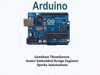
• Arduino Microcontroller
8. Function Micro Processor Micro Controller
Task Multi task Specific task
Consists CPU CPU+Memory+ADC+tim
er+Oscillator+IO ports
Oscillator Speed High clock speed(GHz) Low clock speed(MHz)
Memory Need External Memory Inbuilt Memory
Cost High Low
Example 8085,8086 8051,PIC,AVR
Real Time
Applications
Computer Washing Machine,
Electronic Toys,
Microwave oven etc.,
9.
10. Harvard Architectures
• Used mostly in RISC CPUs
• Separate program bus and data
bus: can be of different widths
• For example, PICs use:
– Data memory (RAM): a small
number of 8bit registers
– Program memory (ROM):
12bit, 14bit or 16bit wide (in
EPROM, FLASH, or ROM)
Von-Neumann Architecture
• Used in: 80X86 (CISC PCs)
• Only one bus between CPU and
memory
• RAM and program memory share
the same bus and the same
memory, and so must have the
same bit width
• Bottleneck: Getting instructions
interferes with accessing RAM
CPU
RAM ROM CPU
RAM
&
ROM
11. Reduced Instruction Set
Computer (RISC)
– Used in: SPARC,
ALPHA, Atmel AVR, etc.
– Few instructions
(usually < 50)
– Only a few addressing
modes
– Executes 1 instruction in
1 internal clock cycle
(Tcyc)
Complex Instruction Set
Computer (CISC)
– Used in: 80X86, 8051,
68HC11, etc.
– Many instructions
(usually > 100)
– Several addressing modes
– Usually takes more than 1
internal clock cycle
(Tcyc) to execute
12. ROM RAM
Read only Read & Write
Non volatile Volatile
Types
PROM
EPROM
EEPROM
Flash
Types
SRAM
DRAM
13. • A compiler is a computer program that transforms source code
written in a programming language into another computer language
(object code).
Example: Turbo C 3.0, Turbo C 4.5
• A cross compiler is similar to the compilers but we write a program
for the target processor (like 8051 and its derivatives) on the host
processors (like computer of x86).
Example: HITECH C, CCS, Keil C
14.
15. INTRO TO THE ARDUINO
• Topics:
• The Arduino
• Digital IO
• Analog IO
• Serial Communication
17. GETTING STARTED
• Check out: http://arduino.cc/en/Guide/HomePage
1. Download & install the Arduino environment (IDE)
(not needed in lab)
2. Connect the board to your computer via the USB cable
3. If needed, install the drivers (not needed in lab)
4. Launch the Arduino IDE
5. Select your board
6. Select your serial port
7. Open the blink example
8. Upload the program
25. ARDUINO DIGITAL I/0
pinMode(pin, mode)
Sets pin to either INPUT or OUTPUT
digitalRead(pin)
Reads HIGH or LOW from a pin
digitalWrite(pin, value)
Writes HIGH or LOW to a pin
Electronic stuff
Output pins can provide 40 mA of current
Writing HIGH to an input pin installs a 20KΩ
pullup
28. EXP1:- Blinking LED
// the setup function runs once when you press reset or power the board
void setup() {
// initialize digital pin 13 as an output.
pinMode(13, OUTPUT);
}
// the loop function runs over and over again forever
void loop() {
digitalWrite(13, HIGH); // turn the LED on (HIGH is the voltage level)
delay(1000); // wait for a second
digitalWrite(13, LOW); // turn the LED off by making the voltage LOW
delay(1000); // wait for a second
}
31. Connect LCD with arduino
Steps:
LCD RS pin to digital pin 12
LCD Enable pin to digital pin 11
LCD D4 pin to digital pin 5
LCD D5 pin to digital pin 4
LCD D6 pin to digital pin 3
LCD D7 pin to digital pin 2
LCD R/W pin to ground
32. EXP3:- LCD Interface
// include the library code:
#include <LiquidCrystal.h>
// initialize the library with the numbers of the interface pins
LiquidCrystal lcd(12, 11, 5, 4, 3, 2);
void setup() {
// set up the LCD's number of columns and rows:
lcd.begin(16, 2);
// Print a message to the LCD.
lcd.print("hello, world!");
}
void loop() {
// Turn off the display:
lcd.noDisplay();
delay(500);
// Turn on the display:
lcd.display();
delay(500);
}
33. Topic 3: Analog Input
• Think about music stored on a CD---an analog signal
captured on digital media
– Sample rate
– Word length
34. • Resolution: the number of different voltage levels (i.e., states) used to
discretize an input signal
• Resolution values range from 256 states (8 bits) to 4,294,967,296 states
(32 bits)
• The Arduino uses 1024 states (10 bits)
• Smallest measurable voltage change is 5V/1024 or 4.8 mV
• Maximum sample rate is 10,000 times a second
Arduino Analog Input
35. How does ADC work?
• How does ADC work
• Excel Demonstration
36. Topic 3: Analog Output
• Can a digital device produce analog output?
• Analog output can be simulated using pulse
width modulation (PWM)
41. Serial Communication
• Compiling turns your program into
binary data (ones and zeros)
• Uploading sends the bits through USB
cable to the Arduino
• The two LEDs near the USB connector
blink when data is transmitted
• RX blinks when the Arduino is
receiving data
• TX blinks when the Arduino is
transmitting data
44. Serial-to-USB chip---what does it do?
The LilyPad and Fio Arduino require an external USB to TTY
connector, such as an FTDI “cable”.
In the Arduino Leonardo a single microcontroller runs the
Arduino programs and handles the USB connection.
47. In-class Exercise 3: Serial
Communication
Modify your program from in-class
exercise 2-part 2 to control the intensity
of the LED attached to pin 9 based on
keyboard input.
Use the Serial.parseInt() method to read
numeric keyboard input as an integer.
An input of 9 should produce full intensity
and an input of 0 should turn the LED off.
48. GSM Transmitter
void setup() {
lcd.begin(16, 2); // set up the LCD's number of columns and rows:
Serial.begin(9600); // initialize the serial communications:
}
void loop()
{
// when characters arrive over the serial port...
Serial.println("AT");
delay(1000);
Serial.println("AT+CMGF=1");
delay(1000);
Serial.println("AT+CMGS="9500546055"");
delay(1000);
Serial.println("HAIO");
delay(1000);
Serial.write(0x1A);
delay(1000); delay(1000); delay(1000); delay(1000); delay(1000); delay(1000); delay(1000); delay(1000);
delay(1000); delay(1000); delay(1000); delay(1000); delay(1000);
while(1);
}
49. Zigbee Transmitter
void setup() {
Serial.begin(9600);
}
void loop() {
Serial.println("H"); //turn on the LED
delay(3000);
Serial.println("L");//turn off the LED
delay(3000);
}
50. Zigbee receiver
char msg = ' '; //contains the message from arduino sender
const int led = 13; //led at pin 13
void setup() {
Serial.begin(9600);//Remember that the baud must be the same on both arduinos
pinMode(led,OUTPUT);
}
void loop() {
while(Serial.available() > 0) {
msg=Serial.read();
if(msg=='H') {
digitalWrite(led,HIGH);
}
if(msg=='L') {
digitalWrite(led,LOW);
}
msg = ' ';
delay(1000);
}
}