Downloaded 1,044 times
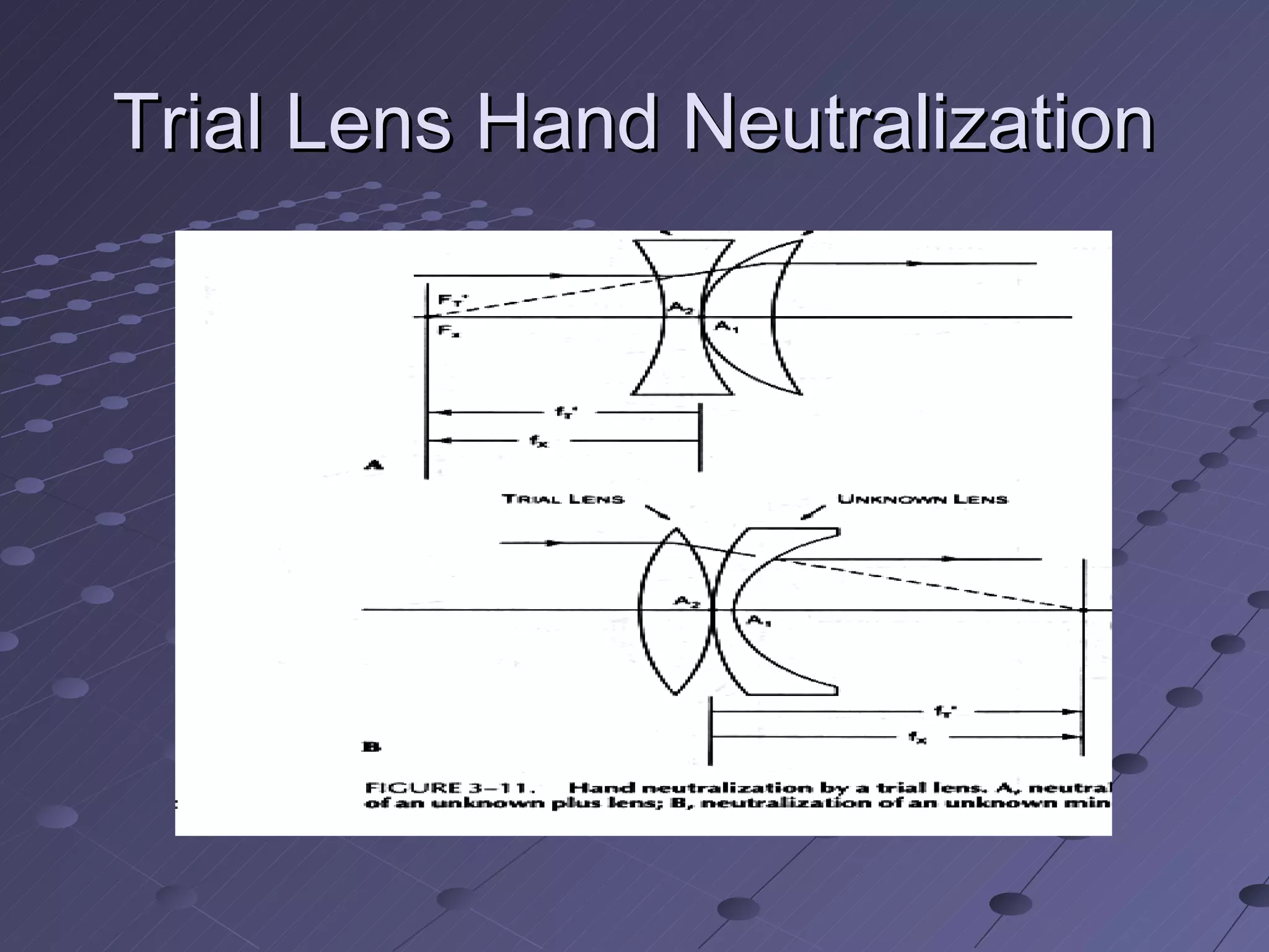
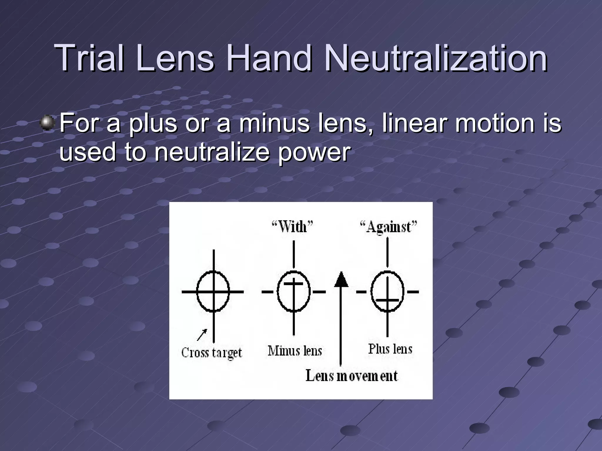
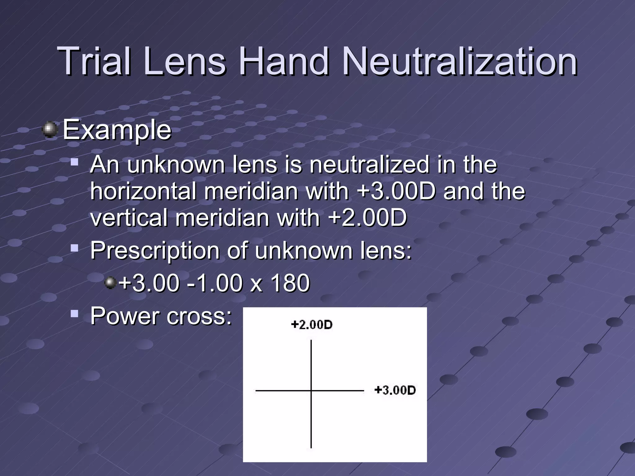
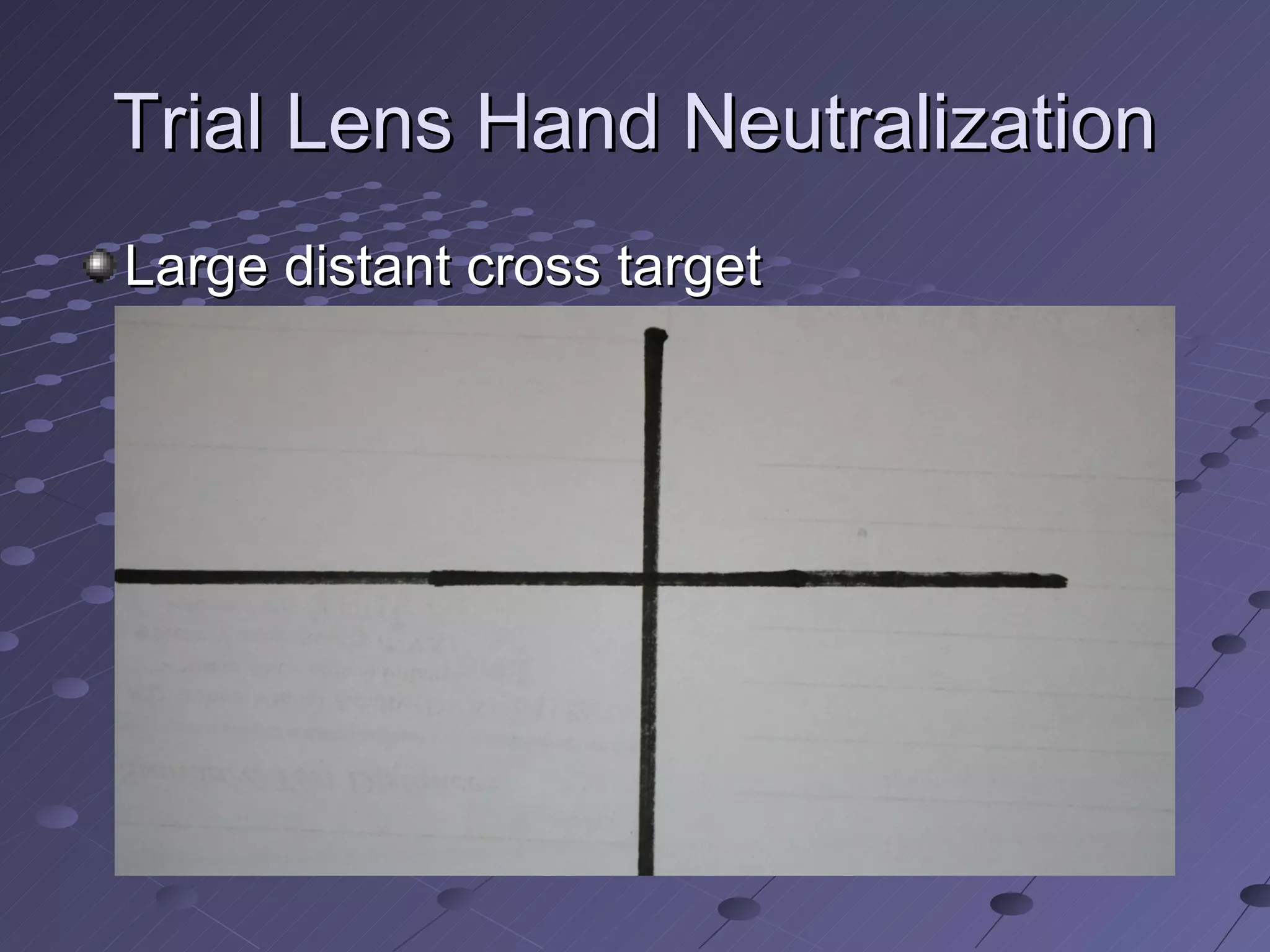
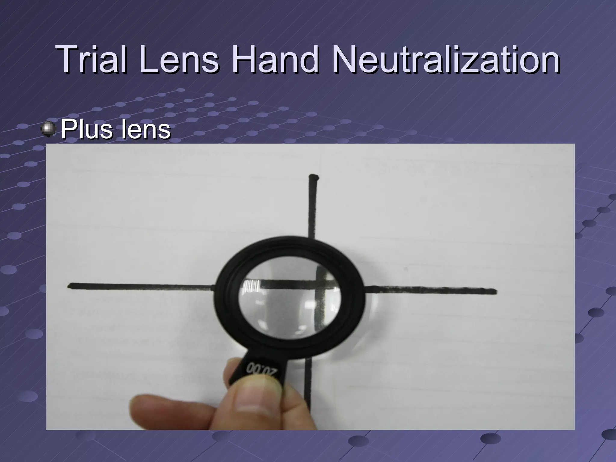
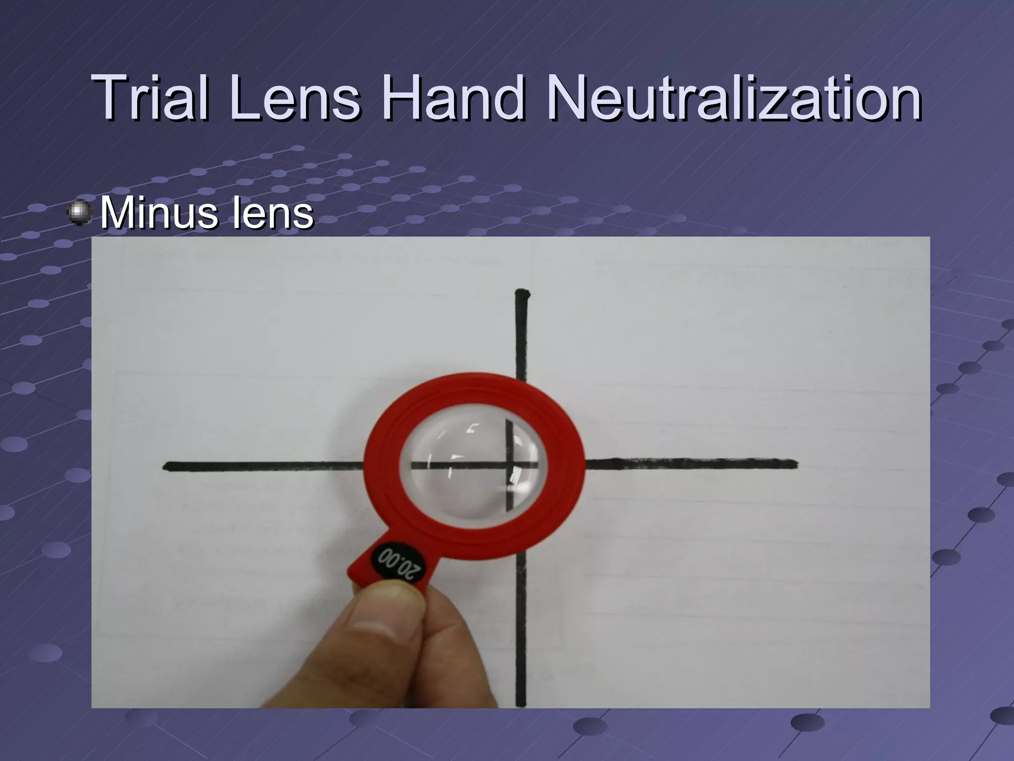
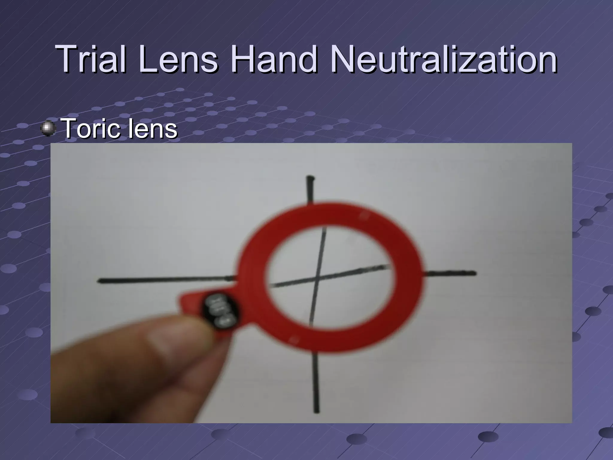
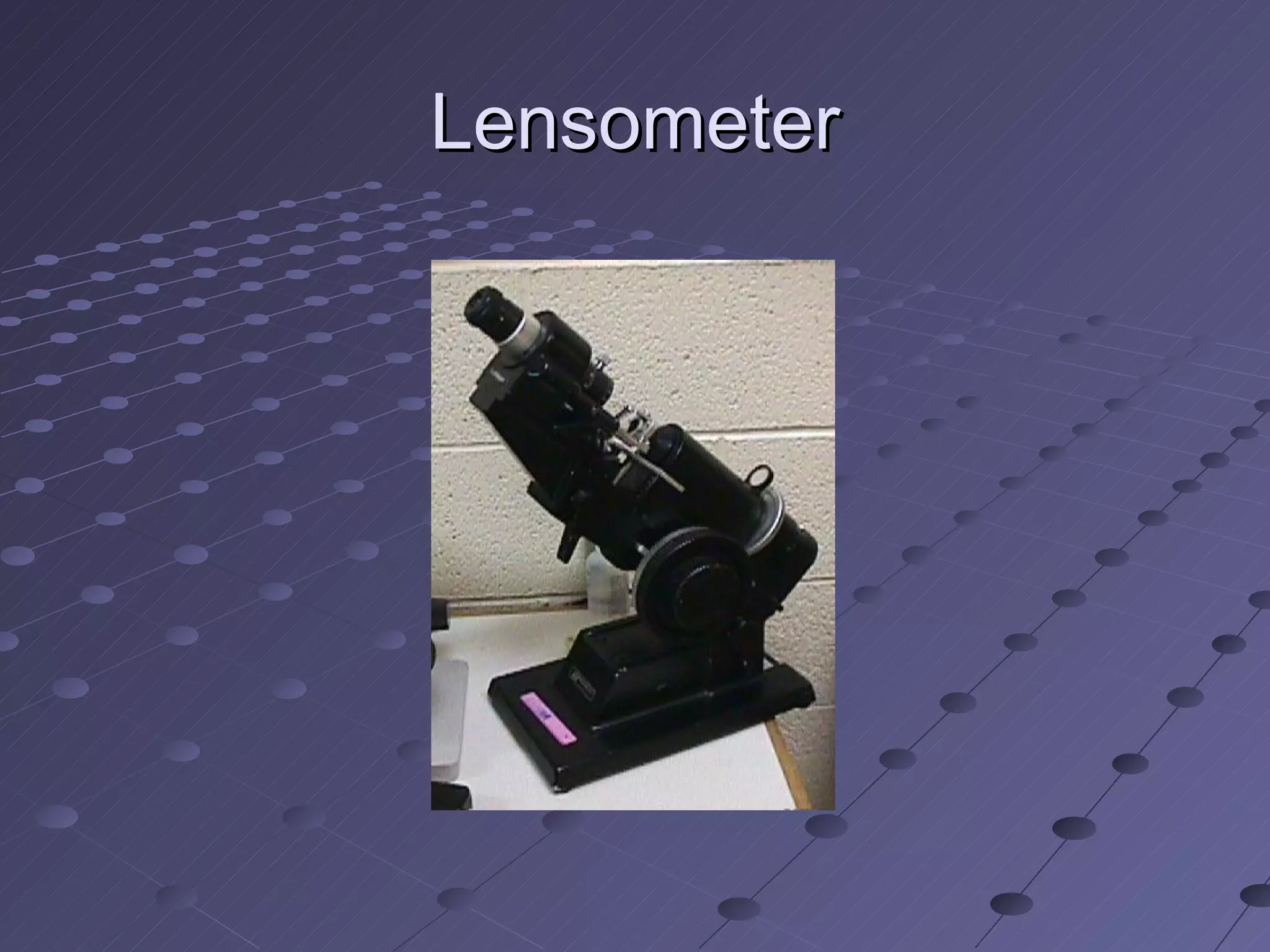

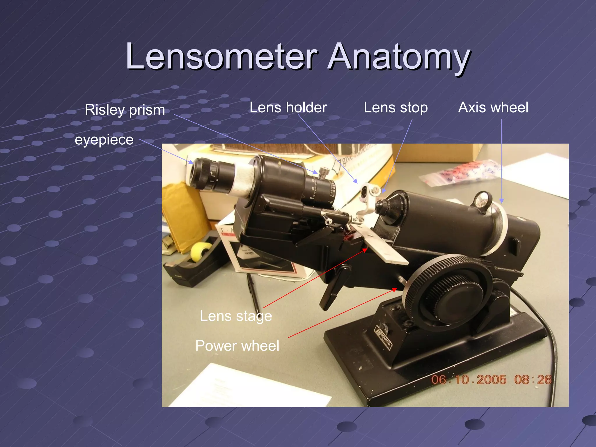
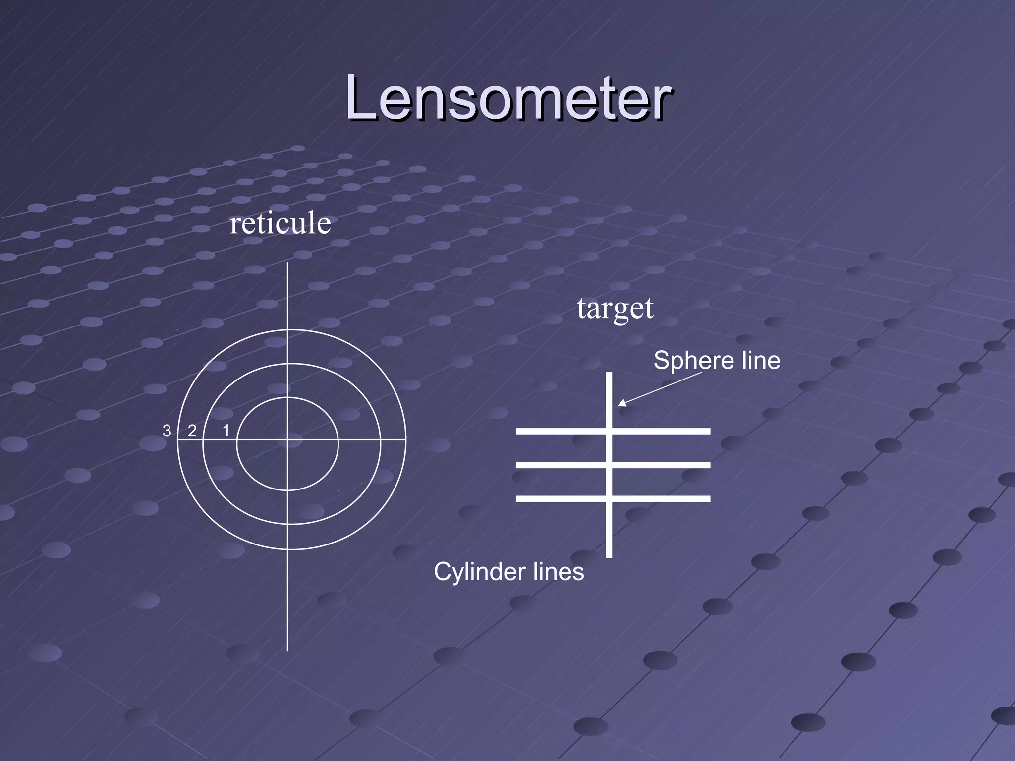
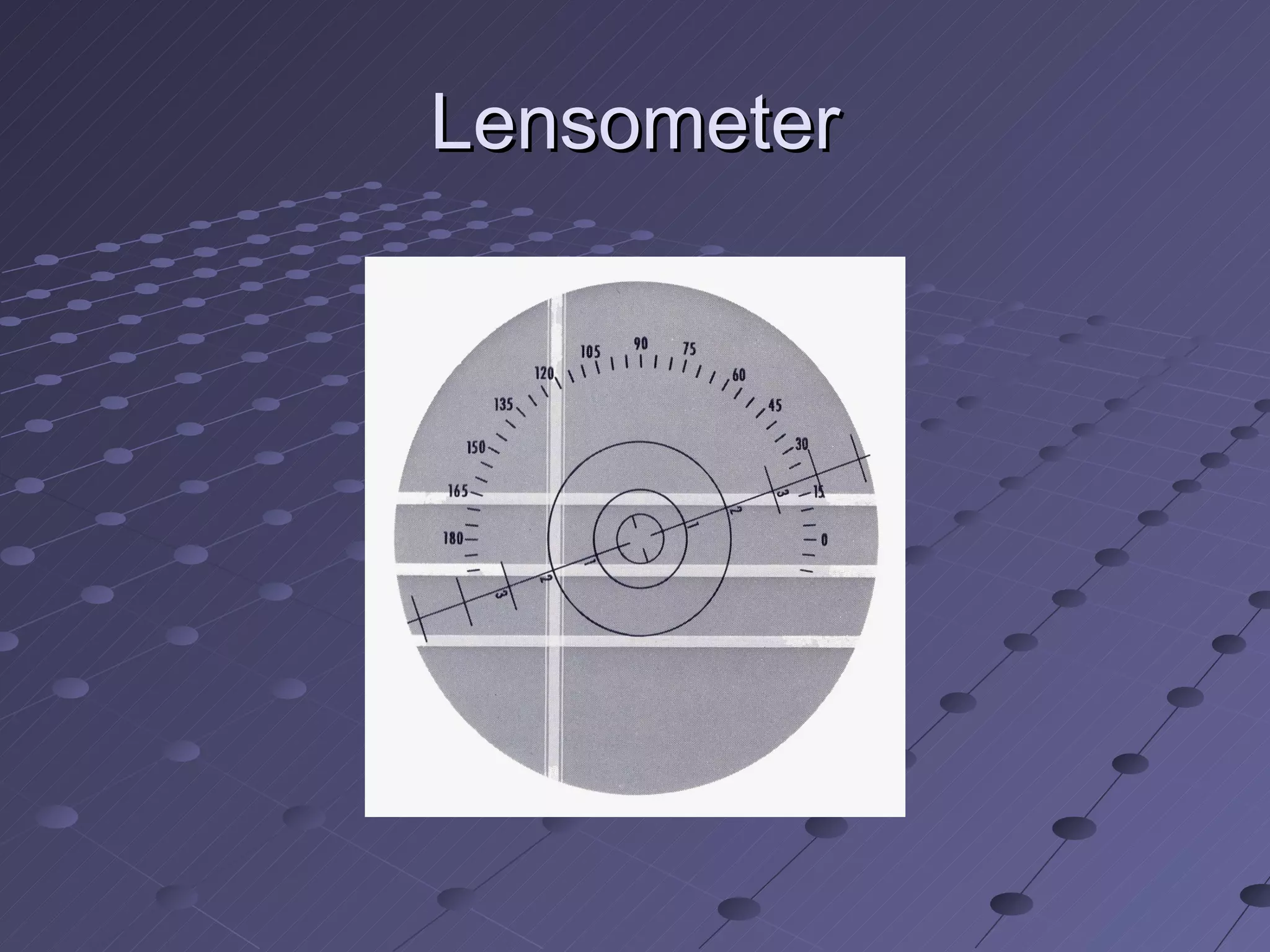


The document discusses two methods for measuring lens power: trial lens hand neutralization which uses linear or rotational motion of trial lenses to estimate power, and lensometry which uses a lensometer device to precisely measure power by neutralizing lenses against a standard lens. It provides details on how each method is performed and the components involved in lensometry measurements.


![Apporach to lung biopsy [Auto-saved].pptx latest](https://cdn.slidesharecdn.com/ss_thumbnails/apporachtolungbiopsyauto-saved-251211225655-93258539-thumbnail.jpg?width=640&height=640&fit=bounds)


