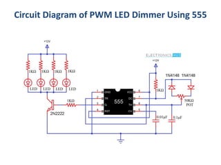
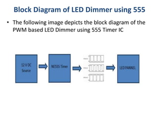
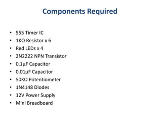
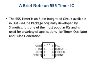
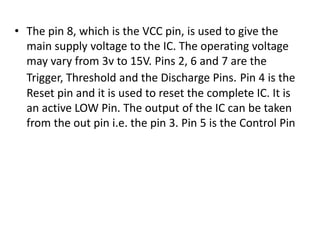
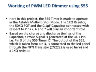
• Introduction
• In this project, we will see a PWM based LED Dimmer
using 555 Timer IC. The main principle of this circuit is to
generate a Pulse Width Modulation PWM Signal with the
help of the good old reliable 555 Timer IC and vary the
power being delivered to the LEDs and hence achieving
the effect of LED Dimming.
• The Pulse Width Modulation (PWM) plays an important
role in controlling the a lot of circuits. If you want to
control the speed of the motor, PWM plays a key role.
Here, in our project, the PWM Technique is used for
dimming the LEDs.
PWM LED Dimmer Using NE555
Circuit Diagram of PWM LED Dimmer Using 555
Block Diagram of LED Dimmer using 555
• The following image depicts the block diagram of the
PWM based LED Dimmer using 555 Timer IC
Components Required
• 555 Timer IC
• 1KΩ Resistor x 6
• Red LEDs x 4
• 2N2222 NPN Transistor
• 0.1μF Capacitor
• 0.01μF Capacitor
• 50KΩ Potentiometer
• 1N4148 Diodes
• 12V Power Supply
• Mini Breadboard
A Brief Note on 555 Timer IC
• The 555 Timer is an 8-pin Integrated Circuit available
in Dual-in-Line Package originally developed by
Signetics. It is one of the most popular ICs and is
used for a variety of applications like Timer, Oscillator
and Pulse Generation.
• The pin 8, which is the VCC pin, is used to give the
main supply voltage to the IC. The operating voltage
may vary from 3v to 15V. Pins 2, 6 and 7 are the
Trigger, Threshold and the Discharge Pins. Pin 4 is the
Reset pin and it is used to reset the complete IC. It is
an active LOW Pin. The output of the IC can be taken
from the out pin i.e. the pin 3. Pin 5 is the Control Pin
Working of PWM LED Dimmer using 555
• Here in this project, the 555 Timer is made to operate
in the Astable Multivibrator Mode. The 1KΩ Resistor,
the 50KΩ POT and the 0.1μF Capacitor connected with
respect to Pins 2, 6 and 7 will play an important role.
• Based on the charge and discharge timings of the
Capacitor, a PWM Signal is generated at the OUT Pin
i.e. Pin 3 of the 555 Timer IC. The output of the 555,
which is taken form pin 3, is connected to the led panel
through the NPN Transistor (2N2222 is used here) and
a 1KΩ resistor.
• The 1KΩ resistor is used to limit the base current of the
transistor and transistor is used as an amplifier to limit
or enhance the current which is given to the LED panel.

Led dimmer

  • 1.
    • Introduction • Inthis project, we will see a PWM based LED Dimmer using 555 Timer IC. The main principle of this circuit is to generate a Pulse Width Modulation PWM Signal with the help of the good old reliable 555 Timer IC and vary the power being delivered to the LEDs and hence achieving the effect of LED Dimming. • The Pulse Width Modulation (PWM) plays an important role in controlling the a lot of circuits. If you want to control the speed of the motor, PWM plays a key role. Here, in our project, the PWM Technique is used for dimming the LEDs. PWM LED Dimmer Using NE555
  • 2.
    Circuit Diagram ofPWM LED Dimmer Using 555
  • 3.
    Block Diagram ofLED Dimmer using 555 • The following image depicts the block diagram of the PWM based LED Dimmer using 555 Timer IC
  • 4.
    Components Required • 555Timer IC • 1KΩ Resistor x 6 • Red LEDs x 4 • 2N2222 NPN Transistor • 0.1μF Capacitor • 0.01μF Capacitor • 50KΩ Potentiometer • 1N4148 Diodes • 12V Power Supply • Mini Breadboard
  • 5.
    A Brief Noteon 555 Timer IC • The 555 Timer is an 8-pin Integrated Circuit available in Dual-in-Line Package originally developed by Signetics. It is one of the most popular ICs and is used for a variety of applications like Timer, Oscillator and Pulse Generation.
  • 6.
    • The pin8, which is the VCC pin, is used to give the main supply voltage to the IC. The operating voltage may vary from 3v to 15V. Pins 2, 6 and 7 are the Trigger, Threshold and the Discharge Pins. Pin 4 is the Reset pin and it is used to reset the complete IC. It is an active LOW Pin. The output of the IC can be taken from the out pin i.e. the pin 3. Pin 5 is the Control Pin
  • 7.
    Working of PWMLED Dimmer using 555 • Here in this project, the 555 Timer is made to operate in the Astable Multivibrator Mode. The 1KΩ Resistor, the 50KΩ POT and the 0.1μF Capacitor connected with respect to Pins 2, 6 and 7 will play an important role. • Based on the charge and discharge timings of the Capacitor, a PWM Signal is generated at the OUT Pin i.e. Pin 3 of the 555 Timer IC. The output of the 555, which is taken form pin 3, is connected to the led panel through the NPN Transistor (2N2222 is used here) and a 1KΩ resistor.
  • 8.
    • The 1KΩresistor is used to limit the base current of the transistor and transistor is used as an amplifier to limit or enhance the current which is given to the LED panel.

Editor's Notes