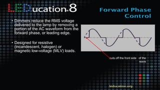
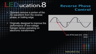
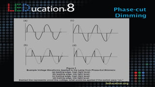
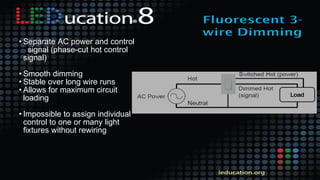
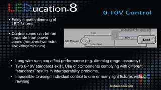
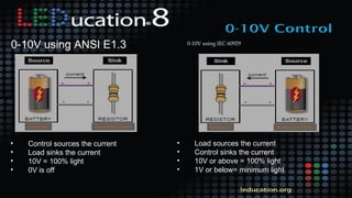
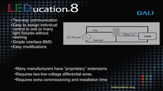
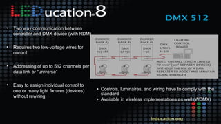
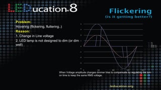
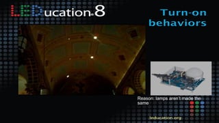
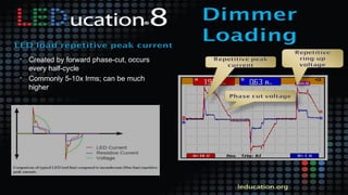
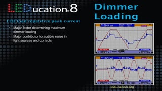
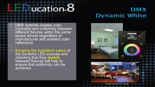
The Crazy World of LED Dimming and
Control
3
Or…
Why The #@*% Is It Doing That?!
• How LEDs work - understanding the basics
• How LEDs dim - different approaches
• What happens when LEDs dim - color, life, efficiency, flicker, noise
• Matchmaking - how to get LEDs, drivers and controls to work together
• Application do’s and don’ts
4
5
Natalia Lupacheva
Systems Engineer
ETC, Middleton, WI
Greg Smith
Director of Product Development
Tivoli, Tustin, CA
Presented by:
Gary Dulanski
Principal
The Dulanski Group, NYC
6
Outline
Gary Dulanski
• Basics of LEDs: how they work, voltages and currents, AC
and DC
• Define drivers and power supplies
• Dimming retrofit LED lamps versus LED fixtures
• Light output vs energy saving when dimming LEDs
• LED life when dimming
• LED color when dimming
7
Outline
Natalia Lupacheva
• Dimmer - Driver - LED interactions
• Phase Control dimming - forward and reverse
• AC + Control Signal dimming - 0-10v, DALI, DMX
• Dimming techniques - Pulse Width Modulation, Constant
Current Reduction
• Flicker issues
• Turn-On behaviors
• Dimmer load restrictions
• NEMA SSL-7A Standard
8
Outline
Greg Smith
• Visual effects
• Range of control, minimum output
• What happens to color when you dim LEDs
• Advantages when using LEDs vs other sources
• Range of LED whites and colors
• Variable / Dynamic white color control
• Warm shifting
• Color tuning
• Lumens vs color
• Automated controls
9
Q & A
• Clarifications anytime
• Big Questions at the end
10
Basic Electricity
• Conductors
• Insulators
• Voltage = Pressure
• Current = Flow
• Load Has Resistance
• Current = V / R
• Power = V x I
• DC = Direct Current,
Current Flows One Way
11
AC
• AC = Alternating Current,
Current Flows Two
Directions
• Frequency Hz
12
Diodes
• SemiConductor
• Diode Conducts Only One Way
• Threshold Voltage To Conduct
• Rectifies AC
13
Light Emitting Diodes
• Electroluminescence
• 1962 Red LED - gallium arsenide
phosphide
• Indicator Lights
• Fast - Fiber Optic Telecommunication
14
LED Circuit• Threshold Voltage To Overcome ~1-3 V
• Limit Current
• Only DC
• Efficiency; consider loss in the limiter
15
Series LED Circuit
• Multiple LEDs Connected
• Higher Supply Voltages
• Efficiency, Less Loss
• One Fails = All Go Out
• Think: Turn On Threshold and Dimming
16
Parallel LED Circuit
• Multiple LEDs
• One Fails, Others Keep Working
• Think: Lower Voltage, Higher Current
17
LED Array
• Series + Parallel
Together
• Screen Backlight Vs
Individually
Controlled LEDs In A
Video Display
18
Driver
• Transform Voltage
• Convert AC To DC
• Drive Correct Current To
LEDs
• Smooth Output
• Compensate For Power
Fluctuations
19
LV Power Supply + Driver
• Line Voltage Converted
To Low Voltage
Separately, Low Voltage
Fed To Fixture
• Driver Circuitry Built Into
Fixture
20
LED Retrofit Lamp
• Driver Built In
21
Dimmable Driver
• Transform Voltage
• Convert AC To DC
• Vary Current To LEDs
• Smooth Output
• Compensate For Power
Fluctuations
• Don’t Misbehave
• Line Voltage Dimmers
DIMDIM
22
DIMDIM
Dimming Driver
• Transform Voltage
• Convert AC To DC
• Vary Current To LEDs
• Smooth Output
• Compensate For Power
Fluctuations
• Don’t Misbehave
• 0-10v, DALI, DMX, 3-Wire Line
Voltage
23
Light Output vs Power
• Depends on LED and
its cooling
• Heat affects efficacy
24
Dimming Performance
• Range Of Dimming ?
• Turn On Behavior ?
• Dimming Curve ?
• Flicker ?
• Eye Response: Perceived
Light = Square Root of
Measured Light
25
Light Output vs Time & Temp
• See DOE Caliper
Testing Reports
• Heat Degrades
• L90, L70
• Cooler LEDs shift less
26
Dimming White LEDs
• Blue + Phosphor
• Lighting Research
Center Study:
Chromaticity Shifts Due To
Different Dimming Methods
27
Dimming White LEDs
• Lighting Research Center Study: Chromaticity Shifts Due To
Different Dimming Methods
• CCR Chromaticity shift yellow • PWM Chromaticity shift blue
28
Color vs Time
• What The …
29
OLED - Organic LED
• Organic Semiconductors
• Thin
• Flexible
• Lifespan
30
Natalia Lupacheva - ETC
• Dimmer - Driver - LED interactions
• Phase Control dimming - forward and reverse
• AC + Control Signal dimming - 0-10v, DALI, DMX
• Dimming techniques - Pulse Width Modulation, Constant
Current Reduction
• Flicker issues
• Turn-On behaviors
• Dimmer load restrictions
• NEMA SSL-7A Standard
Natalia Lupacheva
ETC
1. Coincident AC power and
control signal
• Phase-cut dimming
- forward phase
- reverse phase
2. Separate AC power and
control signal
• Fluorescent 3-Wire
• 0-10V
• DALI
• DMX512
Dimmers reduce the RMS voltage
delivered to the lamp by removing
a portion of the AC waveform from
forward or reverse phase.
• Dimmers reduce the RMS voltage
delivered to the lamp by removing a
portion of the AC waveform from the
forward phase, or leading edge.
• Designed for resistive
(incandescent, halogen) or
magnetic low-voltage (MLV) loads.
cuts off the front side of the
wave
• Dimmers remove a portion of the
AC waveform from the reverse
phase, or trailing edge.
• Originally designed to improve the
performance of low-voltage
halogen lamps operating on
electronic transformers.
cuts off the back end of the
wave
• Separate AC power and control
signal (phase-cut hot control
signal)
• Smooth dimming
• Stable over long wire runs
• Allows for maximum circuit
loading
• Impossible to assign individual
control to one or many light
fixtures without rewiring
• Fairly smooth dimming of
LED fixtures
• Control zones can be run
separate from power
zones (requires two extra
low voltage wire runs)
• Long wire runs can affect performance (e.g. dimming range, accuracy)
• Two 0-10V standards exist. Use of components complying with different
“standards” results in interoperability problems.
• Impossible to assign individual control to one or many light fixtures without
rewiring
0-10V using ANSI E1.3
• Control sources the current
• Load sinks the current
• 10V = 100% light
• 0V is off
0-10V using IEC 60929
• Load sources the current
• Control sinks the current
• 10V or above = 100% light
• 1V or below= minimum light
• Two-way communication
• Easy to assign individual
control to one or many
light fixtures without
rewiring
• Simple interface BMS.
• Easy modifications
•Many manufacturers have “proprietary” extensions
•Requires two low-voltage differential wires
•Requires extra commissioning and installation time
• Two-way communication system that brings digital technology to
lighting
• DALI defines the commands that ballasts need to recognize in
order to be considered DALI ballasts
• Allows for a maximum of 64 fittings on a single network
• DMX512 is a serial protocol used to control lighting equipment
like dimmers, stage lighting and theatrical effects (ex: moving
lights, color changing lights, fog machines, etc.)
• Controls, luminaires, and wiring have to comply with the
standard
• Available in wireless implementations as well (WDMX)
• Two way communication between
controller and DMX device (with RDM)
• Requires two low-voltage wires for
control
• Addressing of up to 512 channels per
data link or “universe”
• Easy to assign individual control to
one or many light fixtures (devices)
without rewiring
Whether separate or integral, the driver electronics determine the
dimming performance of an LED source
Two common methods of dimming LEDs:
•Pulse Width Modulation (PWM)
•Constant Current Reduction (CCR)
LED sources require a “driver””
A PWM based LED dimming driver pulses the LEDs on and off at
a rate of about 240 pulses per second.
• Cameras pick up the pulses - looks like
strobing.
• Potentially undesirable flicker
• Power supplies are more complex and
expensive to manufacture.
• PWM drivers may experience
performance issues if mounted remotely
from the light source
• Provide very precise output level – good
for color mixing
LED dimmed to approximately 25% using PWM
• No noise generation
• Does not create flicker
• Longer wire runs between the driver and
the light engines.
• Color shift below 40%
CCR (analog) driver sends a varying amount of current to the LED
LED that is reduced to approximately 25% using CCR
• Flickering (hovering)
• Flashing/strobing
• Pop-on
• Drop-out
• Dimming smoothness
• Popcorn
• Audible noise
• Dimming range
• Dimmer loading
• Premature failure of dimmer
and/or LED load
• Ghosting
100 lamps on a circuit at control level 75%.
• Flashing from dimmed level to
Full
• Flashing from dimmed level to
Off
• Hovering (flickering, fluttering..)
• Acting like non-dim (On or Off)
• Full to Off or Off to Full
Problem:
Flashing from dimmed level to Full
Reason:
The load is too capacitive for the FPC
(Forward Phase Control) dimmer
Problem:
Flashing from dimmed level to Off
Reason:
Load is not big enough (resistive) for FPC
(Forward Phase Control) dimmer.
Problem:
Acting like non-dim (on or Off)
Reason:
1. LED lamp is not designed to dim
2. Not enough load on a circuit
Problem:
Full to Off or Off to Full
Reason:
Not enough load on a circuit
When Voltage amplitude changes dimmer tries to compensate by regulating the turn
on time to keep the same RMS voltage.
Problem:
Hovering (flickering, fluttering..)
Reason:
1. Change in Line voltage
2. LED lamp is not designed to dim (or dim
well)
Reason: lamps aren’t made the
same
• Created by connection to power,
occurs once per power-up
• Can be 100’s x Irms
Inrush is 65 times higher than rated RMS current.
• Excessive wear on switch or relay
contacts
• Chokes can help to minimize inrush to
dimmer
• Created by forward phase-cut, occurs
every half-cycle
• Commonly 5-10x Irms; can be much
higher
• Major factor determining maximum
dimmer loading
• Major contributor to audible noise in
light sources and controls
• A very brief spike in voltage (above the
instantaneous line voltage) caused by
the discharge of energy-storage
elements
• Can cause long-term damage to
voltage-sensitive components in the
dimmer or lamp
• Caused by interaction between
dimmer and lamp
• Noise can come from the dimmer
itself (If the existing dimmer cost
less than $20, try a dimmer that
uses a toroidal filter or a densely
wound bar choke)
• Noise can come from the lamp
(caused by interaction between
dimmer and lamp)
• Issue with MR16 lamps retrofits
• Two compatibility requirements
• Loading requirements
• Transformers designed for
resistive loads
• Interaction between dimmers and LED light engines
• It is not intended to be used to determine compatibility with existing
(non-compliant) products
Marking requirements
Dimmer
•Maximum rated wattage
•Minimum load
•Type 1/Type 2 compliance
•How to set SSL-7A load type
•LLE
•Minimum light output
•Type 1/Type 2 compliance
• LED product evolution is rapid and product generation life is short
• The LED driver determines dimming performance
• Compatibility must be determined BEFORE products are ordered and installed
• Questions to ask:
- Is the LED product a lamp or luminaire?
- Designed (claimed) dimming performance of the LED?
- What type of control signal is LED designed for?
- Does LED product have a recommended dimmer list,
control type, dimmer loading requirements, etc…
• Perform Mockups
Dimming quality
characteristics such as lack
of flicker, smoothness, or a
specific minimum dimmed
level are best evaluated by
observation, which is why
mockups are so strongly
recommended.
If a mockup is not possible,
use a proven combination of
LED sources and dimmer.
Presented by:
Greg Smith
Tivoli, LLC
64
Greg Smith - Tivoli
• Visual effects:
• Range of control, minimum output
• What happens to color when you dim LEDs
• Advantages when using LEDs vs other sources
• Range of LED whites and colors
• Variable / Dynamic white color control
• Warm shifting
• Color tuning
• Lumens vs color
• Automated controls
• Maximum Lumens are dictated
by circuit design and operating
current
At 350m A – Decisions
need to be made…
Higher Lumens by
Driving current Higher
Trade Off:
•Heat Output
•Life and more
• Minimum Output is based on visual
illumination point
• Dimmer setting value vs.
illumination value percentage
• Low end of output cuts off at 10%
to 20%.
• Based on Dimmer setting Value
vs. illumination percentage value
Minimum Output
• Dimming via PWM:
• Maintain color but have an underlying
“flicker” or “shimmer” while CCR dimmed
LEDs can show a shift in color but
remain smooth.
• What applications makes sense for
each type of dimming?
• LEDs add a new feature to dimming
with adjustable intensity with controlled
color
Source: Electrical Contractor
• Incandescent / Halogen
• Fluorescent
• LED Warm Whites
• LED Colors
Sources warm along the Black Body
Line as the intensity of the light is
reduced.
This has become the model for
residential and entertainment lighting
that LED technology has been moving
towards.
• Have the same adjustable
intensity without the color
shifting qualities of
Incandescent
• Ideal for signage, decorative
and constant illumination
space applications that LEDs
have been able to move into
very well.
LED White colors feature
•Beautiful High CRI
•Tight binning
•Even warm 2200ºK color
Same dimming
characteristics as
White LEDs
Photo Credit: LED
Can we do this
with whites?
Defined as illumination that mimic the
dimming curve of incandescent light
sources.
• Single circuit
• Mimics incandescent sources, warming
color shift as light intensity decreases
• There are limitations of this simple set up
and the affects on Lumens and Color
range
• Set up using 2 colors of LED in the same
fixture space
• Dimming is controlled with the Warmer
color at 100% illumination at all times
• Dimming control is connected to the Brighter
LED circuit
• Work with programmed
controllers or IC chips to
adjust both colors in a
way that mimics the Black
Body curve without the
color Lumens limitations
of the simple Dim to
Warm.
Variable White is similar to our simple Dim to Warm set up except
that both LED colors are connected to controllable dimming circuits.
This can be done in both simple and smart controlled methods.
• Based on 2 color LED mix.
• Low end warm white
• High end cooler white
• Connecting to the 2 LED
colors as separate dimming
control circuits allows the
user to dial in a color based
on intensity levels of each
circuit.
• Control allows
preprogrammed
settings that dial in both
the color mix and
lumens desired for the
lighting with a single
interface
• 4-circuit control
• Offers wider range of color mixing with
variable lumen output and color
temperature
• Dynamic whites are based on the use
of White, Red, Warm White and Yellow
LEDs.
• There can be variances from different
manufacturers of what CCT is used for
the White and Warm White and even
the wavelengths of the Red and Amber
LEDs.
• Already available in some
down light fixtures
• Includes all of these LED
colors and intelligent internal
control
• Creates an illumination that
directly follows the Black Body
line curve
• All Inclusive
• Controllable White
Source: CREE –
preset Sunset
Dimming
• DMX controls creates color
contrasts and uniformity between
different fixtures within the same
space almost regardless of
manufacturer and ambient color
reflections.
• Knowing the ingredient colors of
the Dynamic LED sources and
checking that they match
between fixtures will help to
ensure that uniformity can be
achieved.
What is more important?
• Can other control
applications like external
triggers be the vehicle
for changing the color?
• Change in Intensity
• What about Color?
Motion sensors
Photo Cells
Timers
85
• How LEDs work - understanding the basics
• How LEDs dim - different approaches
• What happens when LEDs dim - color, life, efficiency, flicker, noise
• Matchmaking - how to get LEDs, drivers and controls to work together
• Application do’s and don’ts
86
Panel: Do’s and Dont’s,
Questions and Answers
Gary Dulanski
The Dulanski Group
Natalia Lupacheva
ETC
Greg Smith
Tivoli
87
Gary Dulanski
The Dulanski Group
Natalia Lupacheva
ETC
Greg Smith
Tivoli
Thank You!
Please Fill in Evaluations!
88
Flicker, Buzz and Color Change
The Crazy World of of LED Dimming and Control
March 19, 2014

Session 6 - LEDucation 8 - Controls Presentation - Flicker Buzz & Color

  • 2.
    The Crazy Worldof LED Dimming and Control
  • 3.
    3 Or… Why The #@*%Is It Doing That?!
  • 4.
    • How LEDswork - understanding the basics • How LEDs dim - different approaches • What happens when LEDs dim - color, life, efficiency, flicker, noise • Matchmaking - how to get LEDs, drivers and controls to work together • Application do’s and don’ts 4
  • 5.
    5 Natalia Lupacheva Systems Engineer ETC,Middleton, WI Greg Smith Director of Product Development Tivoli, Tustin, CA Presented by: Gary Dulanski Principal The Dulanski Group, NYC
  • 6.
    6 Outline Gary Dulanski • Basicsof LEDs: how they work, voltages and currents, AC and DC • Define drivers and power supplies • Dimming retrofit LED lamps versus LED fixtures • Light output vs energy saving when dimming LEDs • LED life when dimming • LED color when dimming
  • 7.
    7 Outline Natalia Lupacheva • Dimmer- Driver - LED interactions • Phase Control dimming - forward and reverse • AC + Control Signal dimming - 0-10v, DALI, DMX • Dimming techniques - Pulse Width Modulation, Constant Current Reduction • Flicker issues • Turn-On behaviors • Dimmer load restrictions • NEMA SSL-7A Standard
  • 8.
    8 Outline Greg Smith • Visualeffects • Range of control, minimum output • What happens to color when you dim LEDs • Advantages when using LEDs vs other sources • Range of LED whites and colors • Variable / Dynamic white color control • Warm shifting • Color tuning • Lumens vs color • Automated controls
  • 9.
    9 Q & A •Clarifications anytime • Big Questions at the end
  • 10.
    10 Basic Electricity • Conductors •Insulators • Voltage = Pressure • Current = Flow • Load Has Resistance • Current = V / R • Power = V x I • DC = Direct Current, Current Flows One Way
  • 11.
    11 AC • AC =Alternating Current, Current Flows Two Directions • Frequency Hz
  • 12.
    12 Diodes • SemiConductor • DiodeConducts Only One Way • Threshold Voltage To Conduct • Rectifies AC
  • 13.
    13 Light Emitting Diodes •Electroluminescence • 1962 Red LED - gallium arsenide phosphide • Indicator Lights • Fast - Fiber Optic Telecommunication
  • 14.
    14 LED Circuit• ThresholdVoltage To Overcome ~1-3 V • Limit Current • Only DC • Efficiency; consider loss in the limiter
  • 15.
    15 Series LED Circuit •Multiple LEDs Connected • Higher Supply Voltages • Efficiency, Less Loss • One Fails = All Go Out • Think: Turn On Threshold and Dimming
  • 16.
    16 Parallel LED Circuit •Multiple LEDs • One Fails, Others Keep Working • Think: Lower Voltage, Higher Current
  • 17.
    17 LED Array • Series+ Parallel Together • Screen Backlight Vs Individually Controlled LEDs In A Video Display
  • 18.
    18 Driver • Transform Voltage •Convert AC To DC • Drive Correct Current To LEDs • Smooth Output • Compensate For Power Fluctuations
  • 19.
    19 LV Power Supply+ Driver • Line Voltage Converted To Low Voltage Separately, Low Voltage Fed To Fixture • Driver Circuitry Built Into Fixture
  • 20.
    20 LED Retrofit Lamp •Driver Built In
  • 21.
    21 Dimmable Driver • TransformVoltage • Convert AC To DC • Vary Current To LEDs • Smooth Output • Compensate For Power Fluctuations • Don’t Misbehave • Line Voltage Dimmers DIMDIM
  • 22.
    22 DIMDIM Dimming Driver • TransformVoltage • Convert AC To DC • Vary Current To LEDs • Smooth Output • Compensate For Power Fluctuations • Don’t Misbehave • 0-10v, DALI, DMX, 3-Wire Line Voltage
  • 23.
    23 Light Output vsPower • Depends on LED and its cooling • Heat affects efficacy
  • 24.
    24 Dimming Performance • RangeOf Dimming ? • Turn On Behavior ? • Dimming Curve ? • Flicker ? • Eye Response: Perceived Light = Square Root of Measured Light
  • 25.
    25 Light Output vsTime & Temp • See DOE Caliper Testing Reports • Heat Degrades • L90, L70 • Cooler LEDs shift less
  • 26.
    26 Dimming White LEDs •Blue + Phosphor • Lighting Research Center Study: Chromaticity Shifts Due To Different Dimming Methods
  • 27.
    27 Dimming White LEDs •Lighting Research Center Study: Chromaticity Shifts Due To Different Dimming Methods • CCR Chromaticity shift yellow • PWM Chromaticity shift blue
  • 28.
  • 29.
    29 OLED - OrganicLED • Organic Semiconductors • Thin • Flexible • Lifespan
  • 30.
    30 Natalia Lupacheva -ETC • Dimmer - Driver - LED interactions • Phase Control dimming - forward and reverse • AC + Control Signal dimming - 0-10v, DALI, DMX • Dimming techniques - Pulse Width Modulation, Constant Current Reduction • Flicker issues • Turn-On behaviors • Dimmer load restrictions • NEMA SSL-7A Standard
  • 31.
  • 32.
    1. Coincident ACpower and control signal • Phase-cut dimming - forward phase - reverse phase 2. Separate AC power and control signal • Fluorescent 3-Wire • 0-10V • DALI • DMX512
  • 33.
    Dimmers reduce theRMS voltage delivered to the lamp by removing a portion of the AC waveform from forward or reverse phase.
  • 34.
    • Dimmers reducethe RMS voltage delivered to the lamp by removing a portion of the AC waveform from the forward phase, or leading edge. • Designed for resistive (incandescent, halogen) or magnetic low-voltage (MLV) loads. cuts off the front side of the wave
  • 35.
    • Dimmers removea portion of the AC waveform from the reverse phase, or trailing edge. • Originally designed to improve the performance of low-voltage halogen lamps operating on electronic transformers. cuts off the back end of the wave
  • 37.
    • Separate ACpower and control signal (phase-cut hot control signal) • Smooth dimming • Stable over long wire runs • Allows for maximum circuit loading • Impossible to assign individual control to one or many light fixtures without rewiring
  • 38.
    • Fairly smoothdimming of LED fixtures • Control zones can be run separate from power zones (requires two extra low voltage wire runs) • Long wire runs can affect performance (e.g. dimming range, accuracy) • Two 0-10V standards exist. Use of components complying with different “standards” results in interoperability problems. • Impossible to assign individual control to one or many light fixtures without rewiring
  • 39.
    0-10V using ANSIE1.3 • Control sources the current • Load sinks the current • 10V = 100% light • 0V is off 0-10V using IEC 60929 • Load sources the current • Control sinks the current • 10V or above = 100% light • 1V or below= minimum light
  • 40.
    • Two-way communication •Easy to assign individual control to one or many light fixtures without rewiring • Simple interface BMS. • Easy modifications •Many manufacturers have “proprietary” extensions •Requires two low-voltage differential wires •Requires extra commissioning and installation time
  • 41.
    • Two-way communicationsystem that brings digital technology to lighting • DALI defines the commands that ballasts need to recognize in order to be considered DALI ballasts • Allows for a maximum of 64 fittings on a single network
  • 42.
    • DMX512 isa serial protocol used to control lighting equipment like dimmers, stage lighting and theatrical effects (ex: moving lights, color changing lights, fog machines, etc.)
  • 43.
    • Controls, luminaires,and wiring have to comply with the standard • Available in wireless implementations as well (WDMX) • Two way communication between controller and DMX device (with RDM) • Requires two low-voltage wires for control • Addressing of up to 512 channels per data link or “universe” • Easy to assign individual control to one or many light fixtures (devices) without rewiring
  • 44.
    Whether separate orintegral, the driver electronics determine the dimming performance of an LED source Two common methods of dimming LEDs: •Pulse Width Modulation (PWM) •Constant Current Reduction (CCR) LED sources require a “driver””
  • 45.
    A PWM basedLED dimming driver pulses the LEDs on and off at a rate of about 240 pulses per second. • Cameras pick up the pulses - looks like strobing. • Potentially undesirable flicker • Power supplies are more complex and expensive to manufacture. • PWM drivers may experience performance issues if mounted remotely from the light source • Provide very precise output level – good for color mixing LED dimmed to approximately 25% using PWM
  • 46.
    • No noisegeneration • Does not create flicker • Longer wire runs between the driver and the light engines. • Color shift below 40% CCR (analog) driver sends a varying amount of current to the LED LED that is reduced to approximately 25% using CCR
  • 47.
    • Flickering (hovering) •Flashing/strobing • Pop-on • Drop-out • Dimming smoothness • Popcorn • Audible noise • Dimming range • Dimmer loading • Premature failure of dimmer and/or LED load • Ghosting
  • 48.
    100 lamps ona circuit at control level 75%. • Flashing from dimmed level to Full • Flashing from dimmed level to Off • Hovering (flickering, fluttering..) • Acting like non-dim (On or Off) • Full to Off or Off to Full
  • 49.
    Problem: Flashing from dimmedlevel to Full Reason: The load is too capacitive for the FPC (Forward Phase Control) dimmer Problem: Flashing from dimmed level to Off Reason: Load is not big enough (resistive) for FPC (Forward Phase Control) dimmer. Problem: Acting like non-dim (on or Off) Reason: 1. LED lamp is not designed to dim 2. Not enough load on a circuit Problem: Full to Off or Off to Full Reason: Not enough load on a circuit
  • 50.
    When Voltage amplitudechanges dimmer tries to compensate by regulating the turn on time to keep the same RMS voltage. Problem: Hovering (flickering, fluttering..) Reason: 1. Change in Line voltage 2. LED lamp is not designed to dim (or dim well)
  • 51.
  • 52.
    • Created byconnection to power, occurs once per power-up • Can be 100’s x Irms Inrush is 65 times higher than rated RMS current. • Excessive wear on switch or relay contacts • Chokes can help to minimize inrush to dimmer
  • 53.
    • Created byforward phase-cut, occurs every half-cycle • Commonly 5-10x Irms; can be much higher
  • 54.
    • Major factordetermining maximum dimmer loading • Major contributor to audible noise in light sources and controls
  • 55.
    • A verybrief spike in voltage (above the instantaneous line voltage) caused by the discharge of energy-storage elements • Can cause long-term damage to voltage-sensitive components in the dimmer or lamp • Caused by interaction between dimmer and lamp
  • 56.
    • Noise cancome from the dimmer itself (If the existing dimmer cost less than $20, try a dimmer that uses a toroidal filter or a densely wound bar choke) • Noise can come from the lamp (caused by interaction between dimmer and lamp)
  • 57.
    • Issue withMR16 lamps retrofits • Two compatibility requirements • Loading requirements • Transformers designed for resistive loads
  • 58.
    • Interaction betweendimmers and LED light engines • It is not intended to be used to determine compatibility with existing (non-compliant) products
  • 59.
    Marking requirements Dimmer •Maximum ratedwattage •Minimum load •Type 1/Type 2 compliance •How to set SSL-7A load type •LLE •Minimum light output •Type 1/Type 2 compliance
  • 60.
    • LED productevolution is rapid and product generation life is short • The LED driver determines dimming performance • Compatibility must be determined BEFORE products are ordered and installed • Questions to ask: - Is the LED product a lamp or luminaire? - Designed (claimed) dimming performance of the LED? - What type of control signal is LED designed for? - Does LED product have a recommended dimmer list, control type, dimmer loading requirements, etc… • Perform Mockups
  • 61.
    Dimming quality characteristics suchas lack of flicker, smoothness, or a specific minimum dimmed level are best evaluated by observation, which is why mockups are so strongly recommended. If a mockup is not possible, use a proven combination of LED sources and dimmer.
  • 63.
  • 64.
    64 Greg Smith -Tivoli • Visual effects: • Range of control, minimum output • What happens to color when you dim LEDs • Advantages when using LEDs vs other sources • Range of LED whites and colors • Variable / Dynamic white color control • Warm shifting • Color tuning • Lumens vs color • Automated controls
  • 65.
    • Maximum Lumensare dictated by circuit design and operating current At 350m A – Decisions need to be made… Higher Lumens by Driving current Higher Trade Off: •Heat Output •Life and more
  • 66.
    • Minimum Outputis based on visual illumination point • Dimmer setting value vs. illumination value percentage • Low end of output cuts off at 10% to 20%. • Based on Dimmer setting Value vs. illumination percentage value Minimum Output
  • 67.
    • Dimming viaPWM: • Maintain color but have an underlying “flicker” or “shimmer” while CCR dimmed LEDs can show a shift in color but remain smooth. • What applications makes sense for each type of dimming? • LEDs add a new feature to dimming with adjustable intensity with controlled color Source: Electrical Contractor
  • 68.
    • Incandescent /Halogen • Fluorescent • LED Warm Whites • LED Colors
  • 69.
    Sources warm alongthe Black Body Line as the intensity of the light is reduced. This has become the model for residential and entertainment lighting that LED technology has been moving towards.
  • 70.
    • Have thesame adjustable intensity without the color shifting qualities of Incandescent • Ideal for signage, decorative and constant illumination space applications that LEDs have been able to move into very well.
  • 71.
    LED White colorsfeature •Beautiful High CRI •Tight binning •Even warm 2200ºK color
  • 72.
  • 73.
    Photo Credit: LED Canwe do this with whites?
  • 74.
    Defined as illuminationthat mimic the dimming curve of incandescent light sources.
  • 75.
    • Single circuit •Mimics incandescent sources, warming color shift as light intensity decreases • There are limitations of this simple set up and the affects on Lumens and Color range • Set up using 2 colors of LED in the same fixture space • Dimming is controlled with the Warmer color at 100% illumination at all times • Dimming control is connected to the Brighter LED circuit
  • 76.
    • Work withprogrammed controllers or IC chips to adjust both colors in a way that mimics the Black Body curve without the color Lumens limitations of the simple Dim to Warm.
  • 77.
    Variable White issimilar to our simple Dim to Warm set up except that both LED colors are connected to controllable dimming circuits. This can be done in both simple and smart controlled methods.
  • 78.
    • Based on2 color LED mix. • Low end warm white • High end cooler white • Connecting to the 2 LED colors as separate dimming control circuits allows the user to dial in a color based on intensity levels of each circuit.
  • 79.
    • Control allows preprogrammed settingsthat dial in both the color mix and lumens desired for the lighting with a single interface
  • 80.
    • 4-circuit control •Offers wider range of color mixing with variable lumen output and color temperature • Dynamic whites are based on the use of White, Red, Warm White and Yellow LEDs. • There can be variances from different manufacturers of what CCT is used for the White and Warm White and even the wavelengths of the Red and Amber LEDs.
  • 81.
    • Already availablein some down light fixtures • Includes all of these LED colors and intelligent internal control • Creates an illumination that directly follows the Black Body line curve • All Inclusive • Controllable White Source: CREE – preset Sunset Dimming
  • 82.
    • DMX controlscreates color contrasts and uniformity between different fixtures within the same space almost regardless of manufacturer and ambient color reflections. • Knowing the ingredient colors of the Dynamic LED sources and checking that they match between fixtures will help to ensure that uniformity can be achieved.
  • 83.
    What is moreimportant?
  • 84.
    • Can othercontrol applications like external triggers be the vehicle for changing the color? • Change in Intensity • What about Color? Motion sensors Photo Cells Timers
  • 85.
    85 • How LEDswork - understanding the basics • How LEDs dim - different approaches • What happens when LEDs dim - color, life, efficiency, flicker, noise • Matchmaking - how to get LEDs, drivers and controls to work together • Application do’s and don’ts
  • 86.
    86 Panel: Do’s andDont’s, Questions and Answers Gary Dulanski The Dulanski Group Natalia Lupacheva ETC Greg Smith Tivoli
  • 87.
    87 Gary Dulanski The DulanskiGroup Natalia Lupacheva ETC Greg Smith Tivoli Thank You! Please Fill in Evaluations!
  • 88.
    88 Flicker, Buzz andColor Change The Crazy World of of LED Dimming and Control March 19, 2014

Editor's Notes

  • #66 Maximum Lumens are dictated by circuit design and operating current How it is decided is within the LED itself. In this illustration at 350 mA there are decisions to be made. You can get higher lumens by driving at a higher current. But there are trade offs. Heat output, life and more.
  • #67 Minimum Output is based on visual illumination point. When does the LED turn off in ratio to its overall lumens output capability. Where does that line stop. That should be the definition of the minimum for THAT LED. The key is what is the minimum…LED shuts off at 20% Its different based for every LED. When we see the light turn off. Problem is that there is this communication that is decided by what? The dimmer says it was at 20% but visually Dimmer setting value vs. illumination value percentage Low end of out put cuts off at 10% to 20%. Based on Dimmer setting value vs. based on illumination percentage value. Circle never really goes to 0 – it sort of cuts off at 20% - it is different all LEDs At some level of operating current – reduction to drive these LEDs, they will cut off. Constant current – it will cut off Voltage - <add voltage comparison graph to come>
  • #68 It was discussed earlier that LEDs dimmed via PWM maintain color but have an underlying “flicker” or “shimmer” while CCR dimmed LEDs can show a shift in color but remain smooth. What applications make sense for each type? For the most part, LEDs add a new feature to dimming with adjustable intensity with controlled color. (color shifting) On its own the LEDs do not shift in color they just loose intensity. Because of the elements that are in the room.
  • #69 How do they We know the effects on illumination of both incandescent and Fluorescent sources, but how do they compare to the adjustable intensity with color maintenance of LEDs? People are used to IN and FL sources because of their dimming affect. INC as you dim it..the light output warms, FL acts more like an LED it doesn’t change color it just loose intensity. LED itself has this same characteristic it doesn’t dim to warm or change color.
  • #70 Photo of Incandescent source at 30%, 60% and 100% We know well that that these sources warm along the Black Body Line as the intensity of the light is reduced. This has become the model for residential and entertainment lighting that LED technology has been moving towards The key characteristic is the INC automatically warms which is what you want – but when you would not want this effect to happen. Signage (back lighting with white light – logo stores retail) , decorative niche applications (freezer in grocery store)
  • #71 NEED: Photo of Fluorescent source at 30%, 60% and 100% The lighting from these sources have the same adjustable intensity without the color shifting qualities of Incandescent. This is the model for signage, decorative and constant illumination space applications that LEDs have been able to move into very well It has become a useful lights source as it doesn’t change color when it dims. Where do you see it and why Offices, schools, hospitals, - where you don’t want things changing color.
  • #72 LED White colors from manufacturers have improved greatly in the last 2 years and we now have beautiful High CRI, tightly binned and even warm 2200ºK color available for whites.
  • #73 When we talk about LEDs we know that color LEDs also have the same dimming characteristics as we have described with white LEDs. We have seen these color LEDs used extensively around the world. There are some blended colors. Color LEDs are very color specific but they are intensity controlled. You can control the intensity but it doesn’t shift the color. Which is important when you combine to create mixed shades.
  • #74 We also know that LED colors such as Red, Green and Blue have always been very good for color changing illumination for so many applications such as Televisions. This is because the intensity can be adjusted without the color shifting to allow us to create predictable color mixed illuminations. Can we do this with whites? Most of you here know that the answer is yes.
  • #75 Dim to Warm is defined as illumination that mimics the dimming curve of incandescent light sources. There are simple Dim to Warm control and Smart Dim to Warm control.
  • #76 Simple Dim to Warm can be set up using 2 colors of LED in the same fixture space. The dimming is controlled with the Warmer color at 100% illumination at all times. The dimming control is connected to the Brighter LED circuit. Simple dim to warm – 2 LED colors and take cooler one and put the circuit on a dimmer. When they are at 100% illumination you would have 4400K. When you dim that cool circuit down to 0, then we are at ½ of the LEDs on so it goes from 44K to 28K. Any where I stop on that dimming line is always. If one is cool and 1 is warm, dim the cool all the way off you are left with the warmer one. That provides inexpensive and simple dimming solution. This is a simple way to create a dim to warm circuit. INSERT: Chart showing CCT and lumens of simple Dim to Warm The chart shows us the limitations of this simple set up and the affects on Lumens and color range. However in some applications this can be set up to be inexpensive and effective. This shows the limitation that your bottom end is at 50% of the power and it doesn’t really show lumens. It has a limitation to lumens.
  • #77 Image of a Dim to Warm curve of smart Dim to Warm Smart Dim to warm fixtures work with programmed controllers or IC chips to adjust both colors in a way that mimics the Black Body curve without the color Lumens limitations of the simple Dim to Warm Smart is the idea that we are going to add an interface. We are going to pre-program to tell each LED where we want it to be on the circuit. The program will control the circuit and dim all the way to 0. Dim to warm however you want it by the programming. Programming to follow like an incandescent curve. (control wall interface – slider) DMX
  • #78 Variable White is similar to our simple Dim to Warm set up except that both LED colors are connected to controllable dimming circuits.
  • #79 Image of 2 Dimmer schematic to Linear 2 color LED strip (done as a schematic showing circuit 1 and circuit 2) Variable White – based on 2 color LED mix. Low end warm white, high end cooler white temp. Output controlled with 2 different illumination levels of the 2 colors. Controlled with preset dimming interface that enables color changes along a linear curve of the CCT black body. Simple CCT control only. Connecting to the 2 LED colors as separate dimming control circuits allows the user to dial in a color based on intensity levels of each circuit Now I’m connected to both circuits and I can control both. I can control both circuits of color but cannot control lumen output because it is depedent on how I get to that setting. is can be done in both simple and smart controlled methods Is it more important to dial in a color or to maintain lumens??
  • #80 With Smart Variable white, our control is capable of allowing us to have preprogrammed settings that dial in both the color mix and lumens desired for the lighting with a single interface You have ability to work with 2 colors and dial in a color and change the intensity and do it separately. You can also lower both those circuits in exactly an equal ratio. (google app and slider image)
  • #81 What if like our RGB and our RGBW products we use whites to mix into every possible shade of white via say DMX controls? Dynamic whites are based on the use of White, Red, Warm White and Yellow LEDs. There can be variances from different manufacturers of what CCT is used for the White and Warm White and even the wavelengths of the Red and Amber LEDs.
  • #82 Dynamic white technology can already be seen in some down light fixtures that include all of these LED colors and intelligent internal control to create an illumination that directly follows the Black Body line curve. All inclusive, controllable white – where I can get any white color I want. For example the LMH2 LED module from Cree delivers a natural dimming. The dimming experience providing by the module is very similar to incandescent lighting, dimming smoothly form 2700K to 1800K,
  • #83 Now with Dynamic White Linear strips and fixtures, we can use DMX control to create color contrasts and uniformity between different fixtures within the same space almost regardless of manufacturer and ambient color reflections. Knowing the ingredient colors of the Dynamic LED sources and checking that they match between fixtures will help to ensure that uniformity can be achieved
  • #84 Lumens vs. Color - What is more important? Usually both. As we design a space we need to understand the full capability of the white mixing products that we select based on both these parameters. Different source colors dimmed to different levels. As soon as you start dimming to a different level, you have lost some lumens. Colors you may want to create may take you to 30% or lower of that area 28 with top end 32k Honing in the ranges for the use.
  • #85 Can other control applications like external triggers be the vehicle for changing the color? They can change the intensity but what if they change the color of the room as well? This is an area that is not defined. We as an industry are the ones determining how we want to define it and where we want to take it.