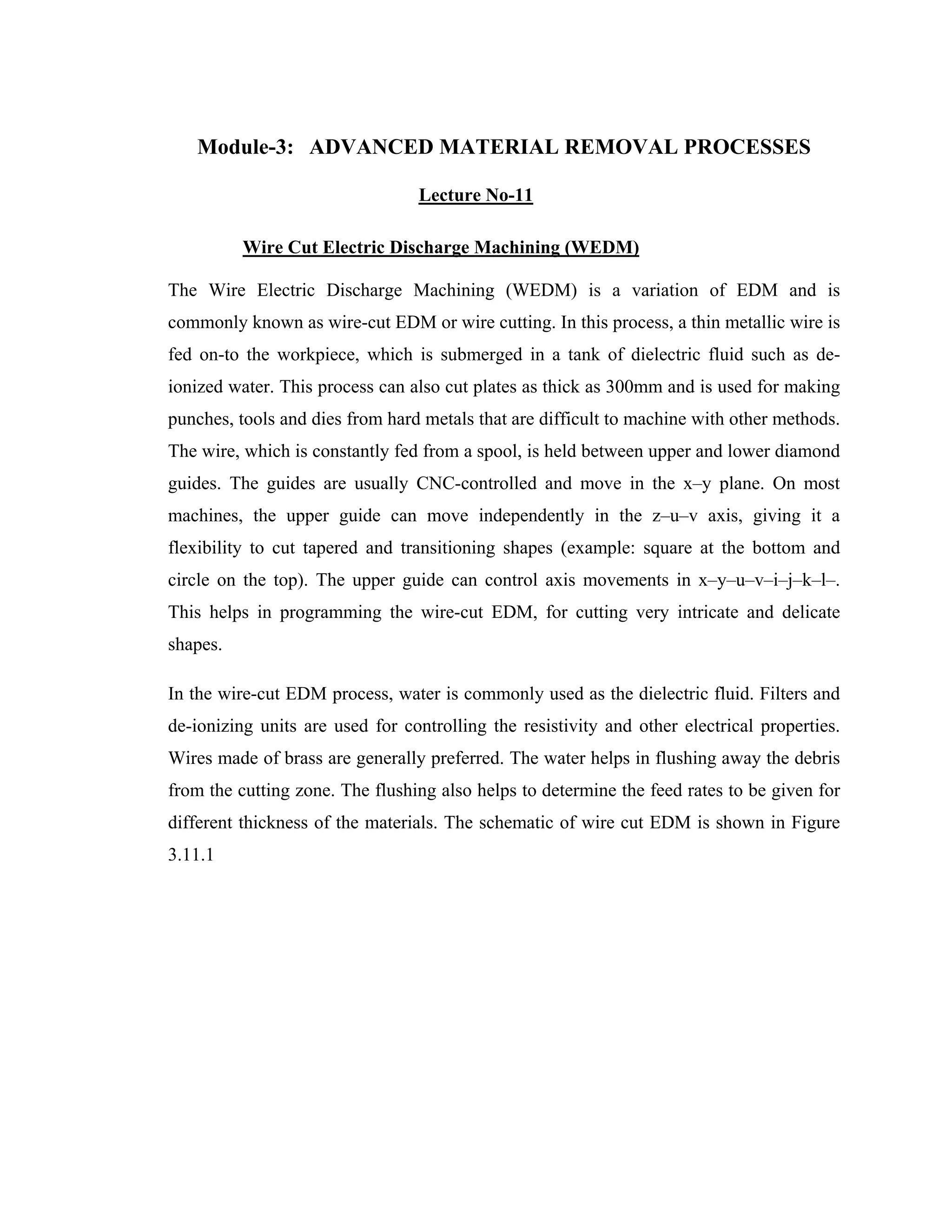
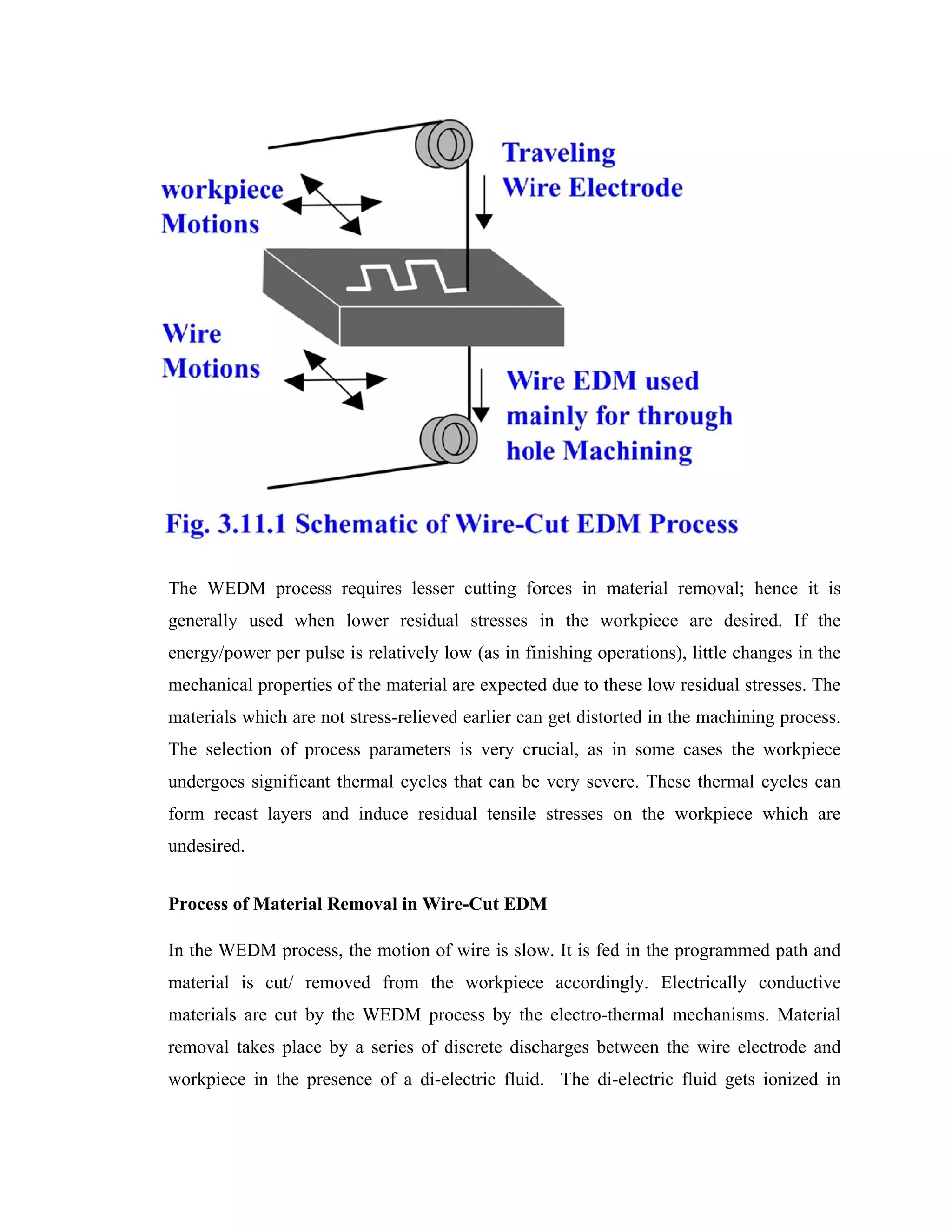
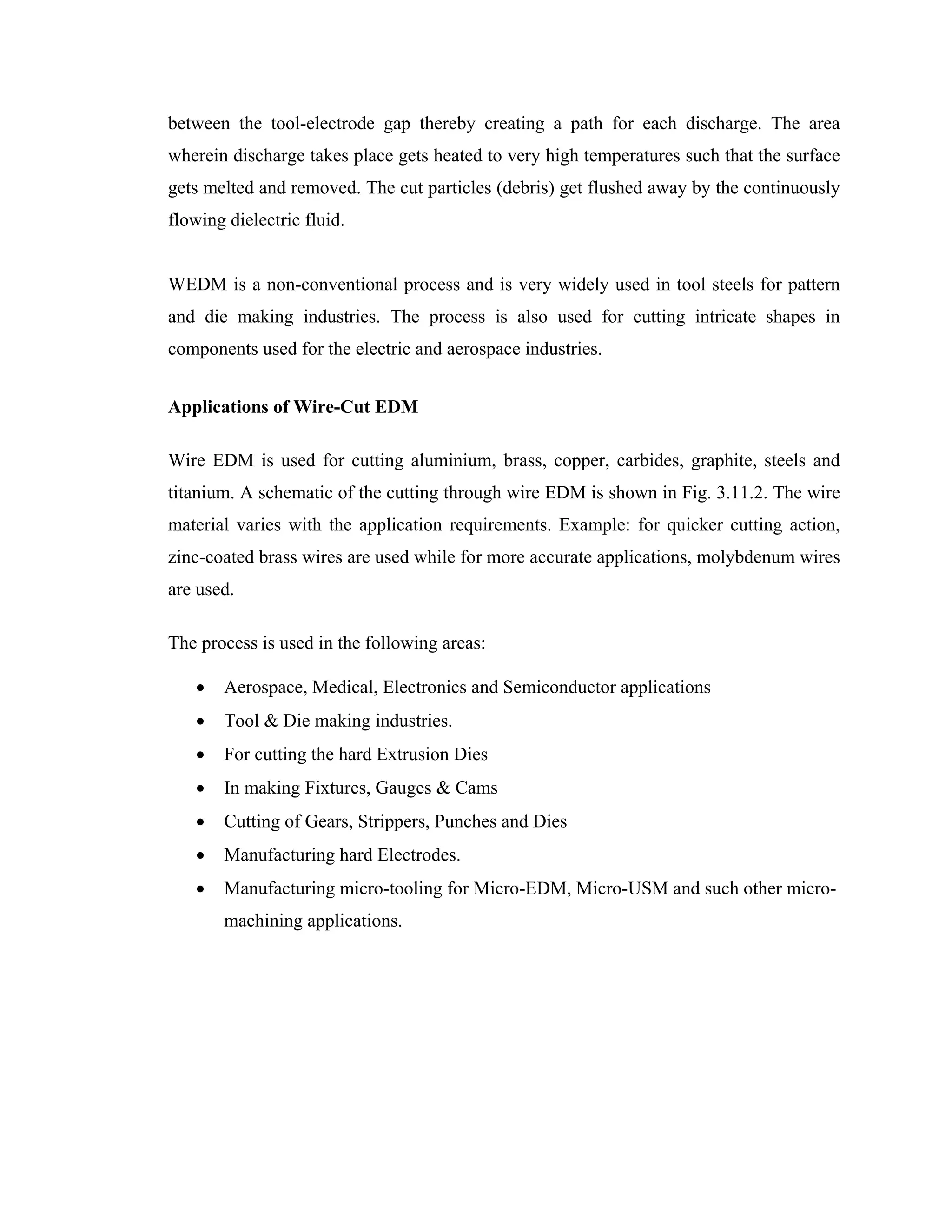
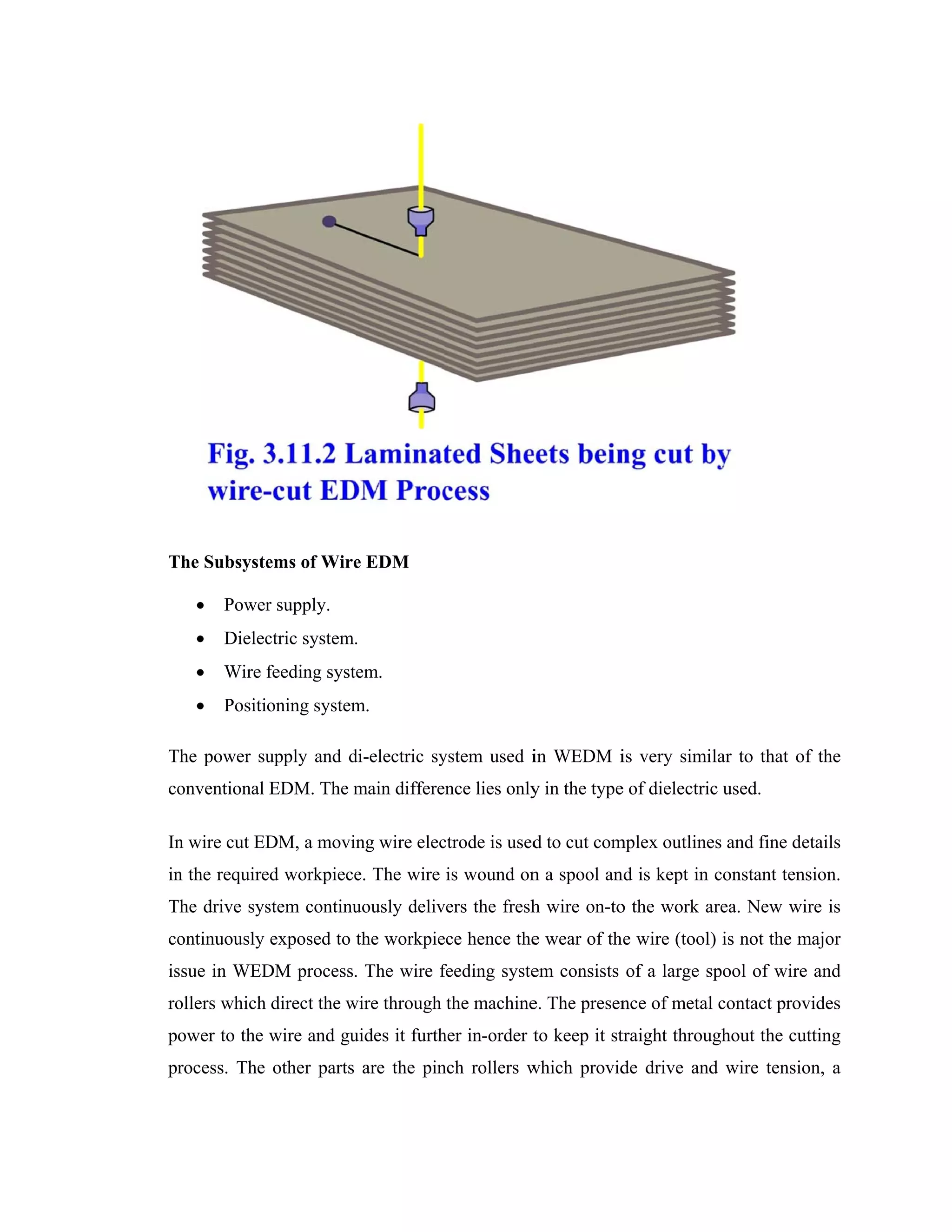
The Wire Electric Discharge Machining (WEDM) process involves a thin metallic wire being fed through upper and lower guides onto a submerged workpiece. Electrical discharges occur between the wire electrode and workpiece, melting and removing small amounts of material. Key parameters that affect the WEDM process include voltage, current, pulse on/off times, wire feed rate, and dielectric fluid properties. WEDM can cut hard metals and complex shapes for applications in aerospace, electronics, and die/mold manufacturing.