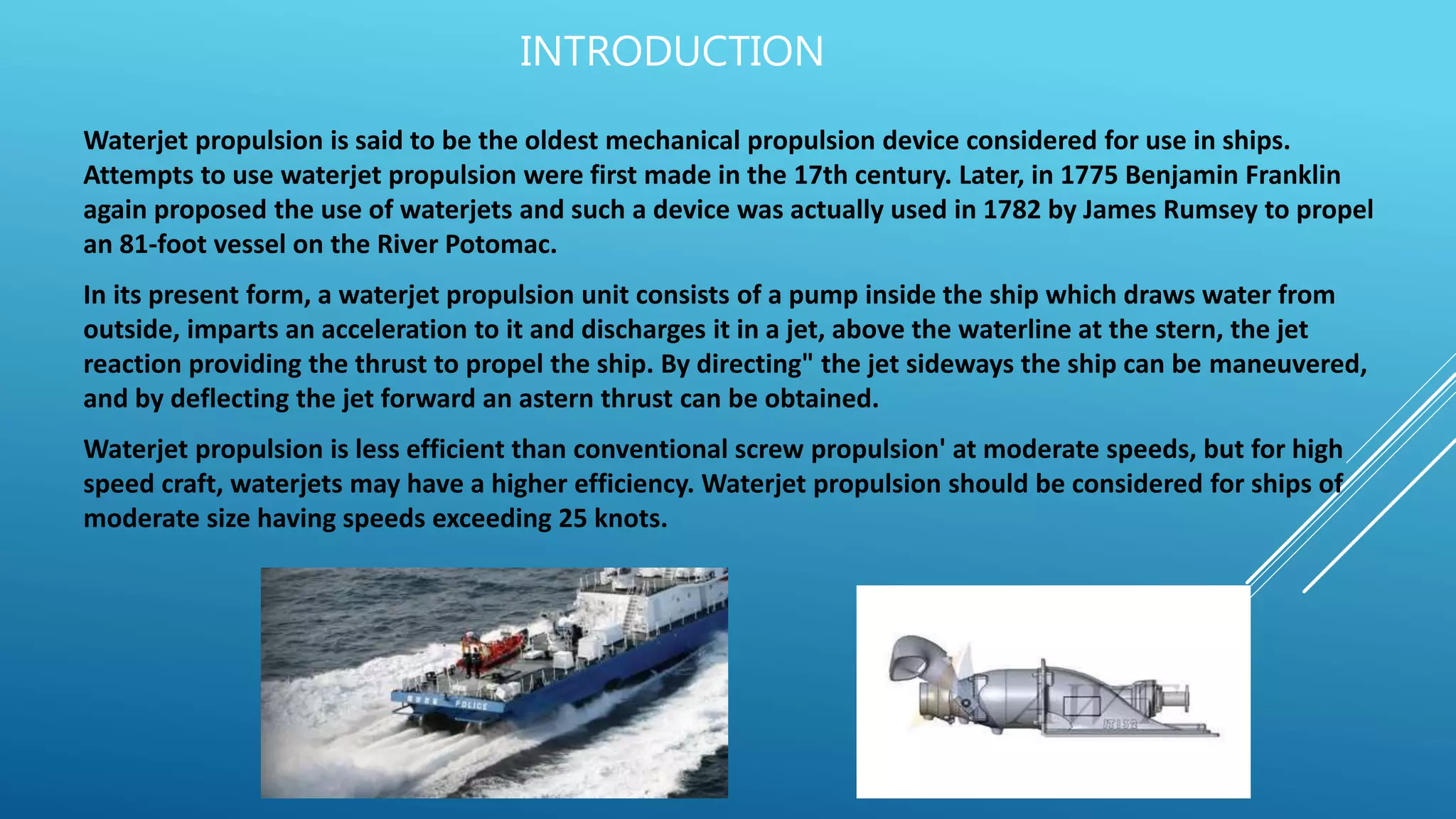
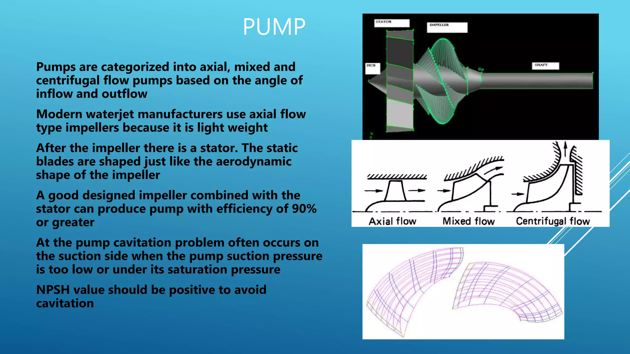
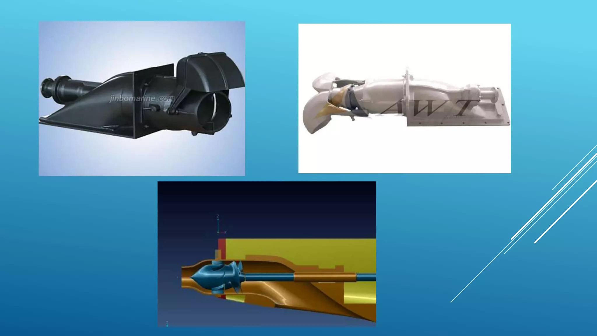
WATERJET
PROPULSION
Group-10
1804609037
1804609038
1804609039
1804609040
INTRODUCTION
Waterjet propulsion is said to be the oldest mechanical propulsion device considered for use in ships.
Attempts to use waterjet propulsion were first made in the 17th century. Later, in 1775 Benjamin Franklin
again proposed the use of waterjets and such a device was actually used in 1782 by James Rumsey to propel
an 81-foot vessel on the River Potomac.
In its present form, a waterjet propulsion unit consists of a pump inside the ship which draws water from
outside, imparts an acceleration to it and discharges it in a jet, above the waterline at the stern, the jet
reaction providing the thrust to propel the ship. By directing" the jet sideways the ship can be maneuvered,
and by deflecting the jet forward an astern thrust can be obtained.
Waterjet propulsion is less efficient than conventional screw propulsion' at moderate speeds, but for high
speed craft, waterjets may have a higher efficiency. Waterjet propulsion should be considered for ships of
moderate size having speeds exceeding 25 knots.
APPLICATION
• Waterjets are used in high-speed pleasure craft (such
as jet skis and jet boats-(a)) and other small vessels.
• Waterjet propulsion is often chosen instead of
conventional propellers for vessels requiring high speeds,
shallow draught, protected propulsion, high
maneuverability at all speeds, low noise emissions for
military applications and low vibration.
• Examples of ships using waterjets are the fast patrol
boat Dvora Mk-III craft, Car Nicobar-class patrol vessels
(b), the Hamina-class missile boats, Valour-class frigates,
the Stena High-speed Sea Service ferries, the United
States Seawolf-class and Virginia-class (c) submarines,
and the United States littoral combat ships.
(b)
(a)
(c)
WORKING PRINCIPLE
• A waterjet generates propulsive thrust from the reaction created when water is forced in a
aftward direction. It works in principle of Newton’s Third Law of Motion – “every action has
an equal and opposite reaction”.
• Most vessels use only a single duct. The fluid passing through the inlet is directed through
the main processing unit of the system. In case of any blockage due to debris near the
inlet, the vessel can be stopped until the debris is cleared.
• The inlet water is a relatively low energy fluid since it is at rest prior to suction. However, in
order to create sufficient thrust, it must be converted into a high energy fluid. This is
accomplished by inducing an element of turbulence using blades. The blades are powered
using an impeller and stator arrangement.
• Due to fluid mechanic responses, sufficient pressure is created using this turbulence and
is then ejected as a high-pressure jet from the nozzle. The impeller is a shaft that is
powered using an onboard motor. It is coupled to the stator that rotates the blades.
 The water enters the jet unit via the Intake (A). The pumping unit, which includes the
Impeller (B) and Stator (C), increases the pressure, or “head”, of the flow. This high
pressure flow is discharged at the nozzle (D) as a high velocity jet stream. The driveshaft
attaches at the coupling (F) to turn the impeller.
 Steering is achieved by changing the direction of the stream of water as it leaves the jet
unit. Reverse is achieved by lowering an astern deflector (E) into the jetstream after it
leaves the nozzle. This reverses the direction of the force generated by the jet stream,
forward and down, to keep the boat stationary or propel it in the astern direction.
HOW ARE WATER JET CRAFTS OPERATED?
 The main controls includes a throttling lever, a steering wheel, and a lever to lower or
raise the astern deflector.
 For acceleration in a forward direction, the throttling lever is gradually increased with the
deflector kept in a raised position. In this condition, the thrust generated by fluid exiting
the nozzle is directed in an aft direction, thus propelling the vessel forwards. By adjusting
the throttling lever, the speed of the vessel can be changed as the fluid exits at faster
rates.
 For turning operations, the steering wheel is used in conjunction with the throttle. The
direction is controlled by the wheel, while the rate of turning is subject to throttling. To
obtain tight turns, high throttle and sharp rotation of the wheel are required
 For reverse, the astern deflector is lowered and the throttle increased. As the throttle
increases, the water jets exiting the nozzle are redirected downwards and in a reverse
manner using the hydrodynamic shape of the deflector. This causes the vessel to move in
a reverse direction. To turn while reversing, the wheel is used to change the direction of
the water jet leaving the deflector. While steering, it is good practice to remember that the
bow always points in the direction in which the steering wheel has been rotated. This
helps especially when reversing, as the turning convention is flipped in this situation.
 Visit : https://youtu.be/Hg-7yJGfdak
GEOMETRY OF WATER JET
PROPULSION SYSTEM
a) Inlet
b) Pump
c) Reducer
d) Bucket
COMMON WATERJET SYSTEMS
• Four different basic types of waterjet propulsion
systems exist
• The major difference between these designs is
the ducting channel geometry and the pump
installation in these systems
a) Flush type intake
b) Ram type intake
c) Planing scoop
d) Scoop intake
INLET
 The shape of the bottom opening which is in flush
with the bottom of the hull needs to be very
carefully designed as it transitions from flush up
into the jet.
 The size of the inlet opening controls the speed of
the flow at the inlet
Major parameters for the inlet design
i. Inlet angle
ii. Ramp tangency point
iii. Ramp radius
iv. Transition angle and the transition length
v. Bending radius
vi. Shaft diameter
 The ingestion of water from outside the hull into the waterjet system has the
effect of suction on the boundary layer around the hull and reduces its
resistance.
 The waterjet inlet is therefore made wide laterally so that the boundary layer
thickness may be reduced over a greater width.
 water ingestion also causes an increase in the relative velocity of water
around the hull and a decrease in pressure (or "thrust deduction"). It is
therefore desirable not to locate the inlet too close to the stern where the
decreased pressure would cause a large increase in resistance.
 An increased inlet duct length would also cause a larger loss in buoyancy to
the ship and occupy more internal space.
 The inlet duct must provide good pressure recovery and low flow distortion.
 the inlet should be located so that there is no possibility of ingestion of air.
PUMP
Pumps are categorized into axial, mixed and
centrifugal flow pumps based on the angle of
inflow and outflow
Modern waterjet manufacturers use axial flow
type impellers because it is light weight
After the impeller there is a stator. The static
blades are shaped just like the aerodynamic
shape of the impeller
A good designed impeller combined with the
stator can produce pump with efficiency of 90%
or greater
At the pump cavitation problem often occurs on
the suction side when the pump suction pressure
is too low or under its saturation pressure
NPSH value should be positive to avoid
cavitation
NOZZLE
 The nozzle converts the pressure into a jet of fast
moving water
 Waterjet works by accelerating water, the nozzle does
most of the acceleration, it achieves that by reducing
the diameter of the pipe in waterjet
 This reduction in diameter causes acceleration of water
 A bad nozzle can reduce the waterjet efficiency to 30%
or less
 The nozzle needs to be tuned for correct speed and
thrust, too much thrust can choke the jet and reduce
the efficiency
 3 dimensional thrust vector control of the nozzle is
possible which can be used in naval fast attack craft
(technology is still under development)
 Eg :- 3D thrust vector control (Su 30mki)
BUCKET
 Controls the direction of the thrust which is
generated by the nozzle
 The bucket adds manuvering capability to the
water jet, it acts like a thrust vectoring device
which vectors the thrust from port to stbd
 The bucket also has a scoop which can come down
over the stream of the jet and directs it out back in
reverse
 To get sufficient thrust of waterjet the engine
needs to run the waterjet at nearly the targeted
rpm about 45-50% power
 The water jet is placed such that it is partially
submerged which helps to convert all the pressure
into velocity
ADVANTAGES OF WATERJET PROPULSION
Waterjets have many advantages over conventional screw propellers:
 - There are no appendages and hence there is a reduction in resistance.
 - Waterjet propulsion can be used in shallow water without any limitation
on the size of the pump_
 - Improved maneuverability, stopping and backing ability are obtained.
 - There is no need to reverse the main engine, i.e. no reversing gear is
required in the propulsion plant.
- The torque of the waterjet unit is constant over the complete speed range,
i.e. full power can be maintained at low speeds without overloading the
engine.
- The speed of the ship from full ahead to full astern can be controlled
without altering the rpm of the engine.
- A higher static thrust can be obtained permitting high acceleration to full
speed.
- There is less noise and vibration.
DISADVANTAGES OF WATERJET PROPULSION
There are two important disadvantages:
 - The waterjet propulsion unit occupies considerable space inside the
ship, and the water passing through ,causes a significant decrease in
buoyancy.
 - It is necessary to provide a grating at the water inlet to prevent
debris from getting in and damaging the pump. This grating decreases
the efficiency of the system, particularly as it gets clogged
REFRENCES
• Waterjet Propulsion- Basic Ship Propulsion by
J.P.Ghose and R.P.Gokran.
• https://en.wikipedia.org/wiki/Pump-jet
 https://youtu.be/Hg-7yJGfdak

Water jet propulsion system

  • 1.
  • 2.
    INTRODUCTION Waterjet propulsion issaid to be the oldest mechanical propulsion device considered for use in ships. Attempts to use waterjet propulsion were first made in the 17th century. Later, in 1775 Benjamin Franklin again proposed the use of waterjets and such a device was actually used in 1782 by James Rumsey to propel an 81-foot vessel on the River Potomac. In its present form, a waterjet propulsion unit consists of a pump inside the ship which draws water from outside, imparts an acceleration to it and discharges it in a jet, above the waterline at the stern, the jet reaction providing the thrust to propel the ship. By directing" the jet sideways the ship can be maneuvered, and by deflecting the jet forward an astern thrust can be obtained. Waterjet propulsion is less efficient than conventional screw propulsion' at moderate speeds, but for high speed craft, waterjets may have a higher efficiency. Waterjet propulsion should be considered for ships of moderate size having speeds exceeding 25 knots.
  • 3.
    APPLICATION • Waterjets areused in high-speed pleasure craft (such as jet skis and jet boats-(a)) and other small vessels. • Waterjet propulsion is often chosen instead of conventional propellers for vessels requiring high speeds, shallow draught, protected propulsion, high maneuverability at all speeds, low noise emissions for military applications and low vibration. • Examples of ships using waterjets are the fast patrol boat Dvora Mk-III craft, Car Nicobar-class patrol vessels (b), the Hamina-class missile boats, Valour-class frigates, the Stena High-speed Sea Service ferries, the United States Seawolf-class and Virginia-class (c) submarines, and the United States littoral combat ships. (b) (a) (c)
  • 4.
    WORKING PRINCIPLE • Awaterjet generates propulsive thrust from the reaction created when water is forced in a aftward direction. It works in principle of Newton’s Third Law of Motion – “every action has an equal and opposite reaction”. • Most vessels use only a single duct. The fluid passing through the inlet is directed through the main processing unit of the system. In case of any blockage due to debris near the inlet, the vessel can be stopped until the debris is cleared. • The inlet water is a relatively low energy fluid since it is at rest prior to suction. However, in order to create sufficient thrust, it must be converted into a high energy fluid. This is accomplished by inducing an element of turbulence using blades. The blades are powered using an impeller and stator arrangement. • Due to fluid mechanic responses, sufficient pressure is created using this turbulence and is then ejected as a high-pressure jet from the nozzle. The impeller is a shaft that is powered using an onboard motor. It is coupled to the stator that rotates the blades.
  • 5.
     The waterenters the jet unit via the Intake (A). The pumping unit, which includes the Impeller (B) and Stator (C), increases the pressure, or “head”, of the flow. This high pressure flow is discharged at the nozzle (D) as a high velocity jet stream. The driveshaft attaches at the coupling (F) to turn the impeller.  Steering is achieved by changing the direction of the stream of water as it leaves the jet unit. Reverse is achieved by lowering an astern deflector (E) into the jetstream after it leaves the nozzle. This reverses the direction of the force generated by the jet stream, forward and down, to keep the boat stationary or propel it in the astern direction.
  • 6.
    HOW ARE WATERJET CRAFTS OPERATED?  The main controls includes a throttling lever, a steering wheel, and a lever to lower or raise the astern deflector.  For acceleration in a forward direction, the throttling lever is gradually increased with the deflector kept in a raised position. In this condition, the thrust generated by fluid exiting the nozzle is directed in an aft direction, thus propelling the vessel forwards. By adjusting the throttling lever, the speed of the vessel can be changed as the fluid exits at faster rates.  For turning operations, the steering wheel is used in conjunction with the throttle. The direction is controlled by the wheel, while the rate of turning is subject to throttling. To obtain tight turns, high throttle and sharp rotation of the wheel are required  For reverse, the astern deflector is lowered and the throttle increased. As the throttle increases, the water jets exiting the nozzle are redirected downwards and in a reverse manner using the hydrodynamic shape of the deflector. This causes the vessel to move in a reverse direction. To turn while reversing, the wheel is used to change the direction of the water jet leaving the deflector. While steering, it is good practice to remember that the bow always points in the direction in which the steering wheel has been rotated. This helps especially when reversing, as the turning convention is flipped in this situation.  Visit : https://youtu.be/Hg-7yJGfdak
  • 7.
    GEOMETRY OF WATERJET PROPULSION SYSTEM a) Inlet b) Pump c) Reducer d) Bucket
  • 8.
    COMMON WATERJET SYSTEMS •Four different basic types of waterjet propulsion systems exist • The major difference between these designs is the ducting channel geometry and the pump installation in these systems a) Flush type intake b) Ram type intake c) Planing scoop d) Scoop intake
  • 9.
    INLET  The shapeof the bottom opening which is in flush with the bottom of the hull needs to be very carefully designed as it transitions from flush up into the jet.  The size of the inlet opening controls the speed of the flow at the inlet Major parameters for the inlet design i. Inlet angle ii. Ramp tangency point iii. Ramp radius iv. Transition angle and the transition length v. Bending radius vi. Shaft diameter
  • 10.
     The ingestionof water from outside the hull into the waterjet system has the effect of suction on the boundary layer around the hull and reduces its resistance.  The waterjet inlet is therefore made wide laterally so that the boundary layer thickness may be reduced over a greater width.  water ingestion also causes an increase in the relative velocity of water around the hull and a decrease in pressure (or "thrust deduction"). It is therefore desirable not to locate the inlet too close to the stern where the decreased pressure would cause a large increase in resistance.  An increased inlet duct length would also cause a larger loss in buoyancy to the ship and occupy more internal space.  The inlet duct must provide good pressure recovery and low flow distortion.  the inlet should be located so that there is no possibility of ingestion of air.
  • 11.
    PUMP Pumps are categorizedinto axial, mixed and centrifugal flow pumps based on the angle of inflow and outflow Modern waterjet manufacturers use axial flow type impellers because it is light weight After the impeller there is a stator. The static blades are shaped just like the aerodynamic shape of the impeller A good designed impeller combined with the stator can produce pump with efficiency of 90% or greater At the pump cavitation problem often occurs on the suction side when the pump suction pressure is too low or under its saturation pressure NPSH value should be positive to avoid cavitation
  • 12.
    NOZZLE  The nozzleconverts the pressure into a jet of fast moving water  Waterjet works by accelerating water, the nozzle does most of the acceleration, it achieves that by reducing the diameter of the pipe in waterjet  This reduction in diameter causes acceleration of water  A bad nozzle can reduce the waterjet efficiency to 30% or less  The nozzle needs to be tuned for correct speed and thrust, too much thrust can choke the jet and reduce the efficiency  3 dimensional thrust vector control of the nozzle is possible which can be used in naval fast attack craft (technology is still under development)  Eg :- 3D thrust vector control (Su 30mki)
  • 13.
    BUCKET  Controls thedirection of the thrust which is generated by the nozzle  The bucket adds manuvering capability to the water jet, it acts like a thrust vectoring device which vectors the thrust from port to stbd  The bucket also has a scoop which can come down over the stream of the jet and directs it out back in reverse  To get sufficient thrust of waterjet the engine needs to run the waterjet at nearly the targeted rpm about 45-50% power  The water jet is placed such that it is partially submerged which helps to convert all the pressure into velocity
  • 14.
    ADVANTAGES OF WATERJETPROPULSION Waterjets have many advantages over conventional screw propellers:  - There are no appendages and hence there is a reduction in resistance.  - Waterjet propulsion can be used in shallow water without any limitation on the size of the pump_  - Improved maneuverability, stopping and backing ability are obtained.  - There is no need to reverse the main engine, i.e. no reversing gear is required in the propulsion plant.
  • 15.
    - The torqueof the waterjet unit is constant over the complete speed range, i.e. full power can be maintained at low speeds without overloading the engine. - The speed of the ship from full ahead to full astern can be controlled without altering the rpm of the engine. - A higher static thrust can be obtained permitting high acceleration to full speed. - There is less noise and vibration.
  • 16.
    DISADVANTAGES OF WATERJETPROPULSION There are two important disadvantages:  - The waterjet propulsion unit occupies considerable space inside the ship, and the water passing through ,causes a significant decrease in buoyancy.  - It is necessary to provide a grating at the water inlet to prevent debris from getting in and damaging the pump. This grating decreases the efficiency of the system, particularly as it gets clogged
  • 18.
    REFRENCES • Waterjet Propulsion-Basic Ship Propulsion by J.P.Ghose and R.P.Gokran. • https://en.wikipedia.org/wiki/Pump-jet  https://youtu.be/Hg-7yJGfdak