The document discusses regulations regarding aircraft airworthiness set by the Federal Aviation Administration (FAA). It outlines standards for maximum takeoff weights, structural integrity, safety systems, and performance metrics that must be met. It also discusses requirements for aircraft engines and propellers, including standards for blade design and pitch control mechanisms.
FARs, arerules prescribed by the Federal
Aviation Administration
governing all aviation activities in the United
States.
3.
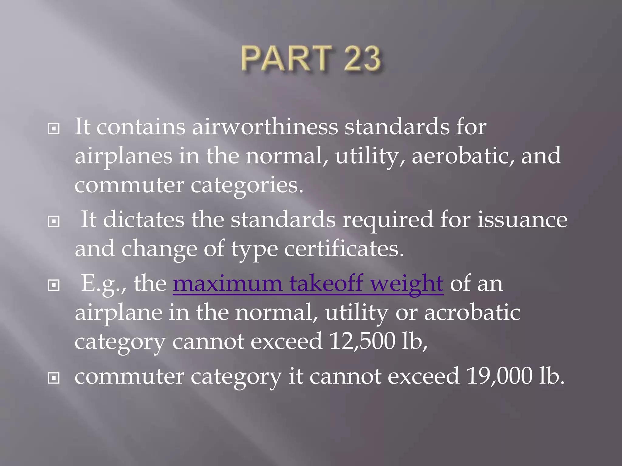
It containsairworthiness standards for
airplanes in the normal, utility, aerobatic, and
commuter categories.
It dictates the standards required for issuance
and change of type certificates.
E.g., the maximum takeoff weight of an
airplane in the normal, utility or acrobatic
category cannot exceed 12,500 lb,
commuter category it cannot exceed 19,000 lb.
4.
This parthas a large number of regulations to ensure
airworthiness in areas such as structural loads, airframe,
performance, stability, controllability, and safety
mechanisms, how the seats must be constructed, oxygen
and air pressurization systems, fire prevention, escape
hatches, flight management procedures, flight control
communications, emergency landing procedures, and other
limitations, as well as testing of all the systems of the
aircraft.
It also determines special aspects of aircraft performance
such as stall speed (e.g., for single engine airplanes – not
more than 61 knots), rate of climb (not less than 300 ft/min),
take-off speed (not less than 1.2 x VS1), and weight of each
pilot and passenger (170 lb for airplanes in the normal and
commuter categories, and 190 lb for airplanes in the
acrobatic and utility categories).
5.
An aircraftengine is the component of
the propulsion system that generates
mechanical power.
Aircraft engines are almost always either
lightweight piston engines or gas turbines.
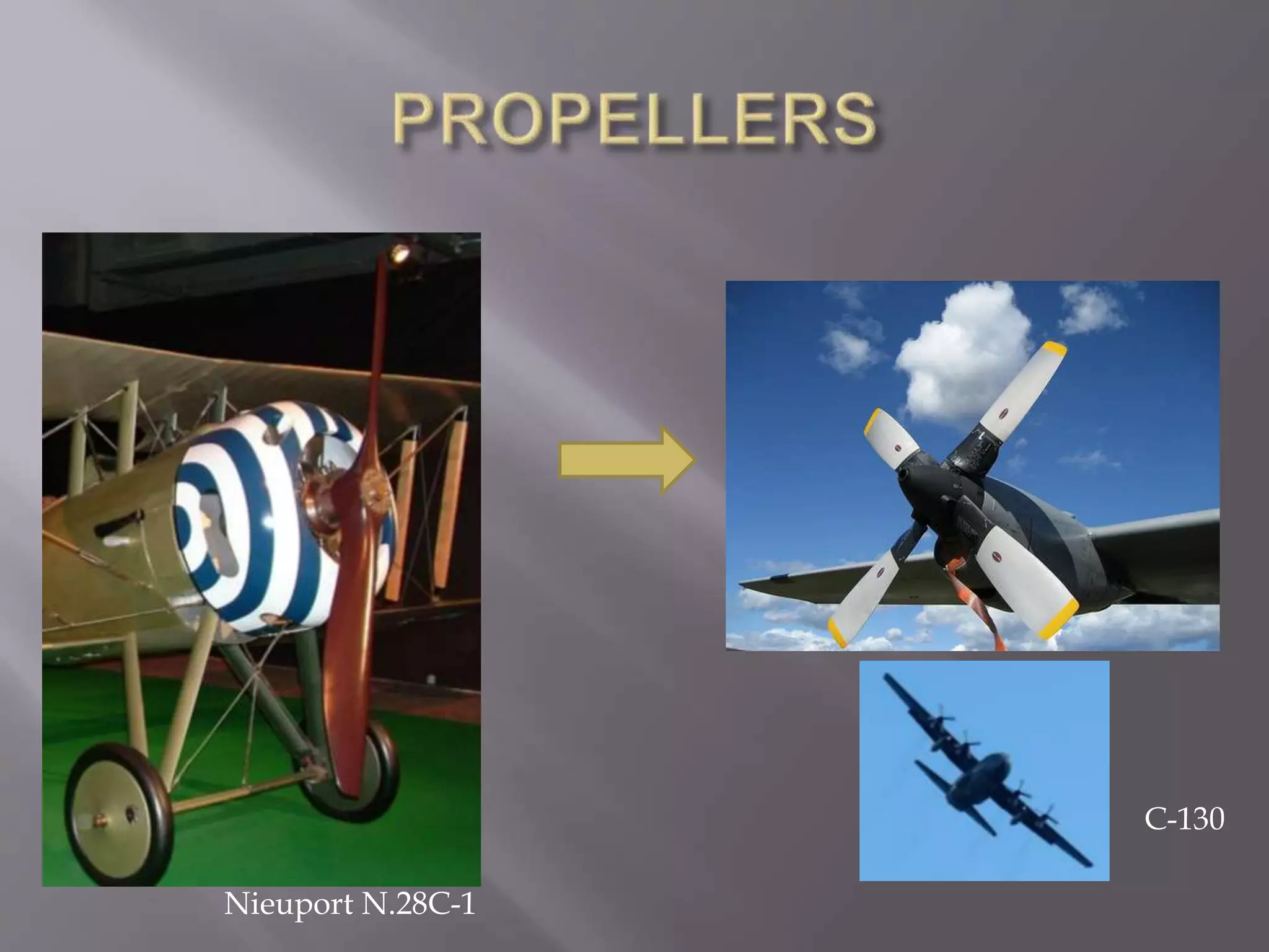
propeller convertsrotary motion from an engine to
provide propulsive force.
It comprises a rotating power-driven hub, to which
are attached several radial airfoil-section
The blade pitch may be fixed, manually variable to
a few set positions, or of the automatically-variable
"constant-speed" type.
Introduction
13.
It attachesto the power source's driveshaft either
directly reduction gearing.
Materials
only suitable for use at subsonic airspeeds up to
around 480 mph (770 kph),
above this speed the blade tip speed begins to go
supersonic, with the consequent shockwaves
causing high drag and other mechanical difficulties.
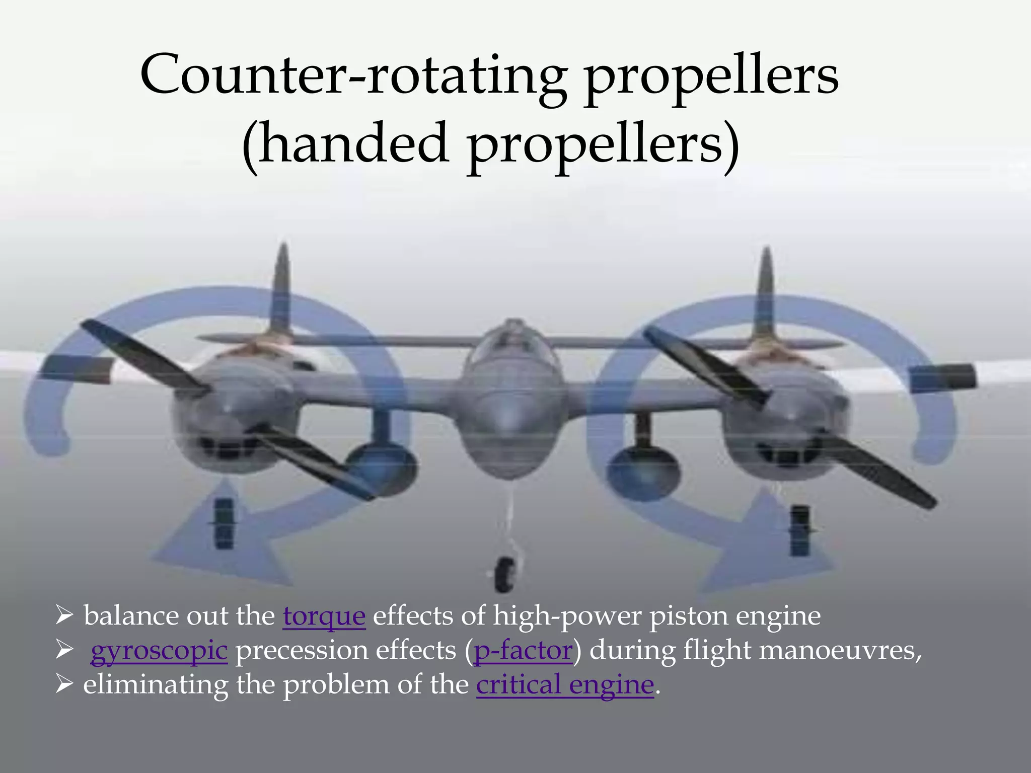
Counter-rotating propellers
(handed propellers)
balance out the torque effects of high-power piston engine
gyroscopic precession effects (p-factor) during flight manoeuvres,
eliminating the problem of the critical engine.
The forwardpropeller provides the majority of
the thrust,
The rear propeller also recovers energy lost in
the swirling motion of the air in the propeller
slipstream.
Provide good circulation strength.
increases the ability of absorb power from
engine, without increasing propeller diameter.
added cost, complexity, weight and noise of the
system
it is only used on high-performance types where
ultimate performance is more important than
efficiency.
22.
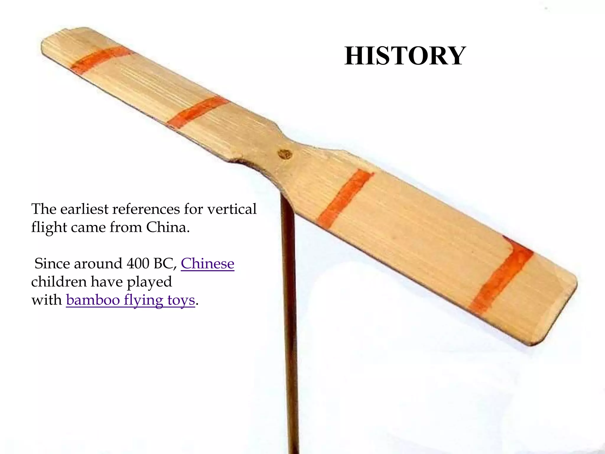
The earliest referencesfor vertical
flight came from China.
Since around 400 BC, Chinese
children have played
with bamboo flying toys.
HISTORY
23.
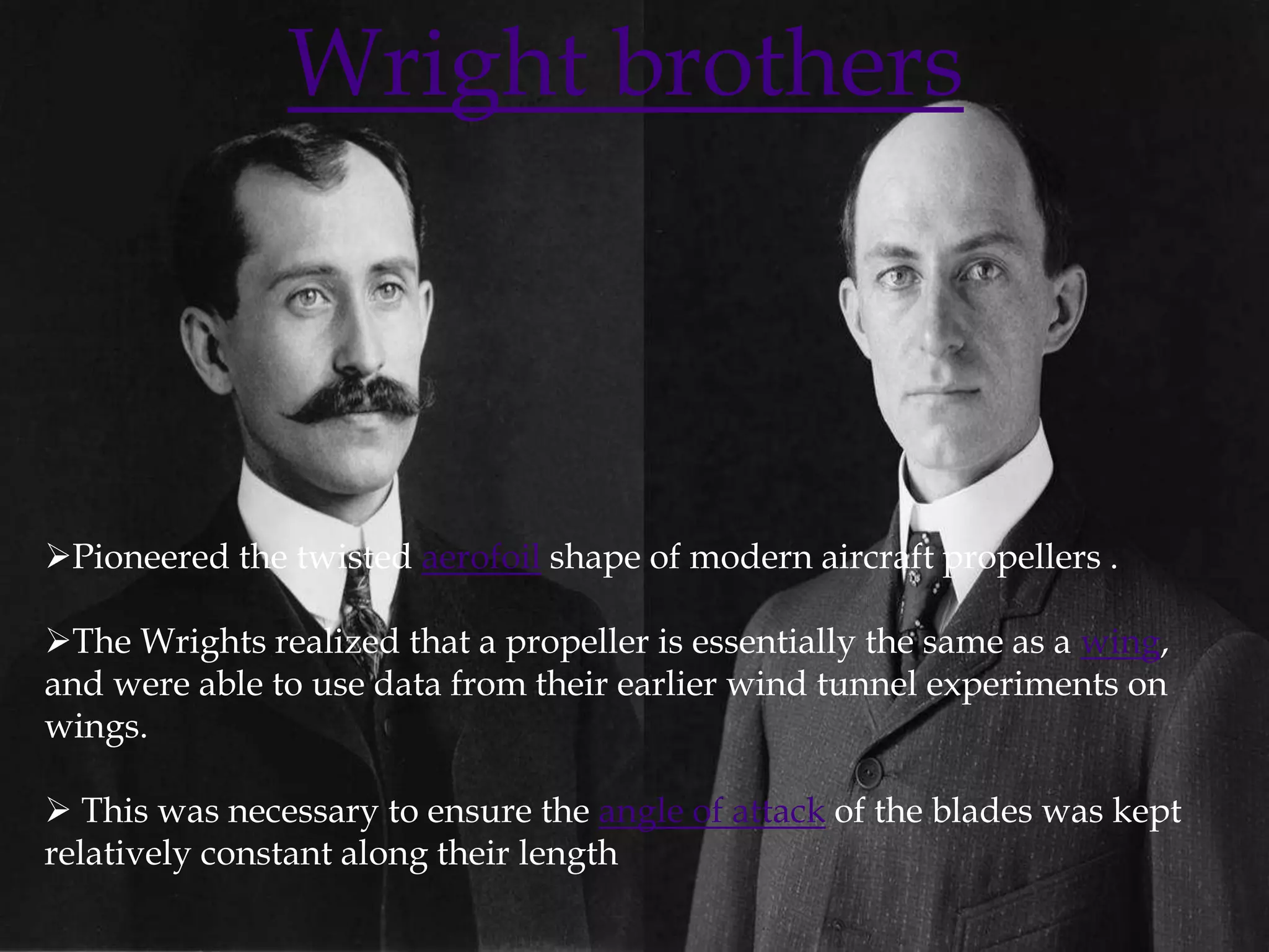
Pioneered the twistedaerofoil shape of modern aircraft propellers .
The Wrights realized that a propeller is essentially the same as a wing,
and were able to use data from their earlier wind tunnel experiments on
wings.
This was necessary to ensure the angle of attack of the blades was kept
relatively constant along their length
Wright brothers
24.
early pioneer,make a propeller with a steel
shaft and aluminium blades for his 14 bis
biplane.
Some of his designs used a bent aluminium
sheet for blades, thus creating an airfoil shape.
They were heavily undercambered, absence of
lengthwise twist made them less efficient than
the Wright propellers.
Alberto Santos Dumont
26.
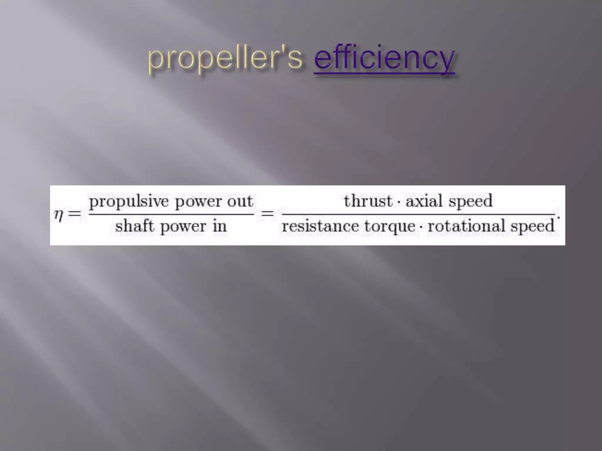
A well-designedpropeller typically has an
efficiency of around 80% when operating in the
best regime.
The efficiency of the propeller is influenced by
the angle of attack (α). This is defined as
α = Φ – θ
where θ is the helix angle (the angle between
the resultant relative velocity and the blade
rotation direction)
Φ is the blade pitch angle.
27.
Propellers aresimilar in aerofoil section to a
low-drag wing
Efficiency is poor in when at other than their
optimum angle of attack.
Therefore, some propellers use a variable
pitch mechanism to alter the blades' pitch angle
as engine speed and aircraft velocity are
changed.
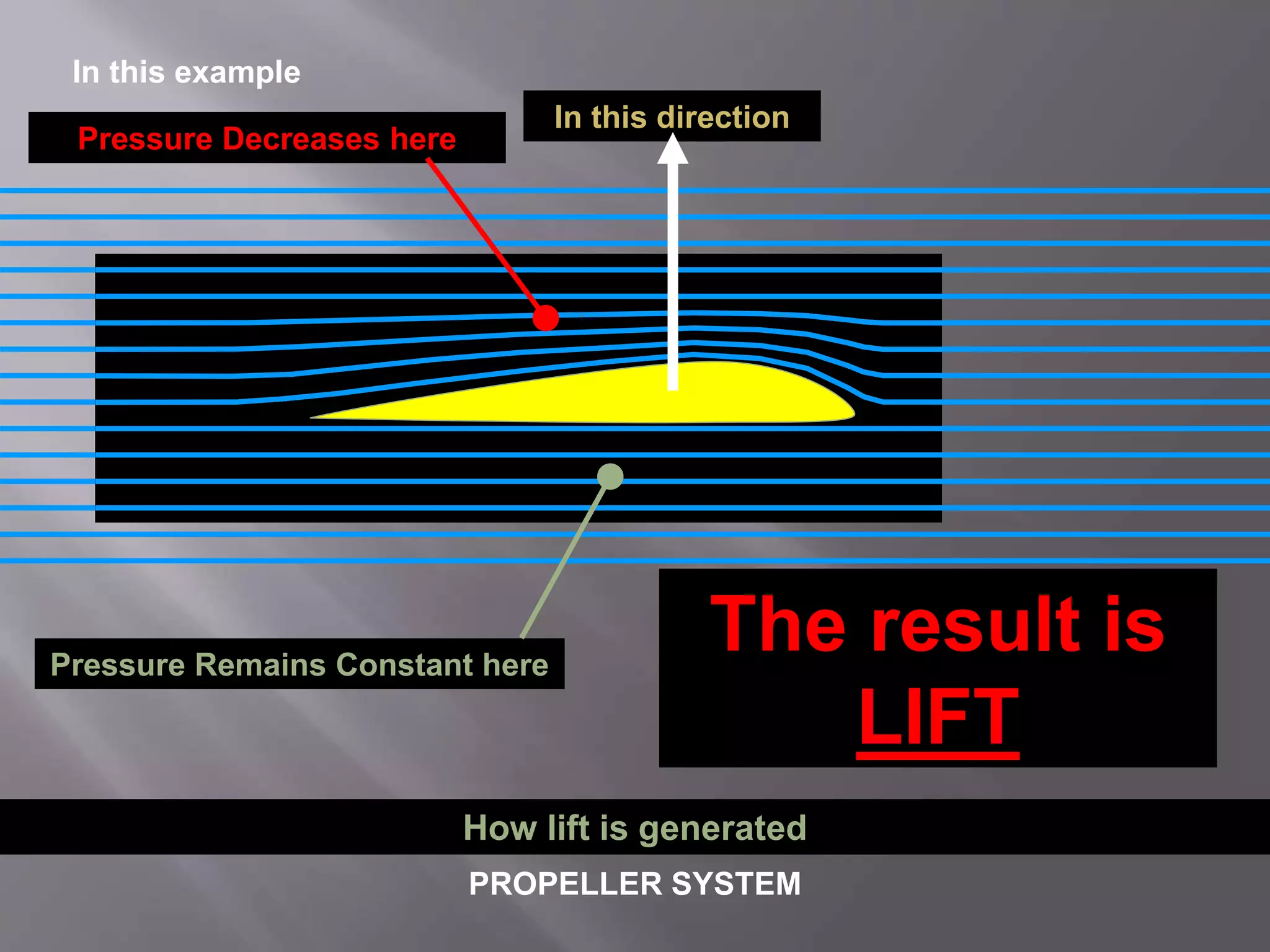
In this example
PressureRemains Constant here
Pressure Decreases here
In this direction
The result is
LIFT
How lift is generated
PROPELLER SYSTEM
30.
Small Pressure Increasehere
Greater Pressure Decrease
here
The result is
MORE LIFT
How lift is increased
PROPELLER SYSTEM
31.
Direction of travel
Thedifference in direction of travel and aerofoil incline is called:-
The ANGLE of ATTACK
How lift is increased
PROPELLER SYSTEM
32.
How does liftapply to PROPELLORS?
On Propellers, LIFT is called THRUST
And propeller Blades work the same way as aircraft wings
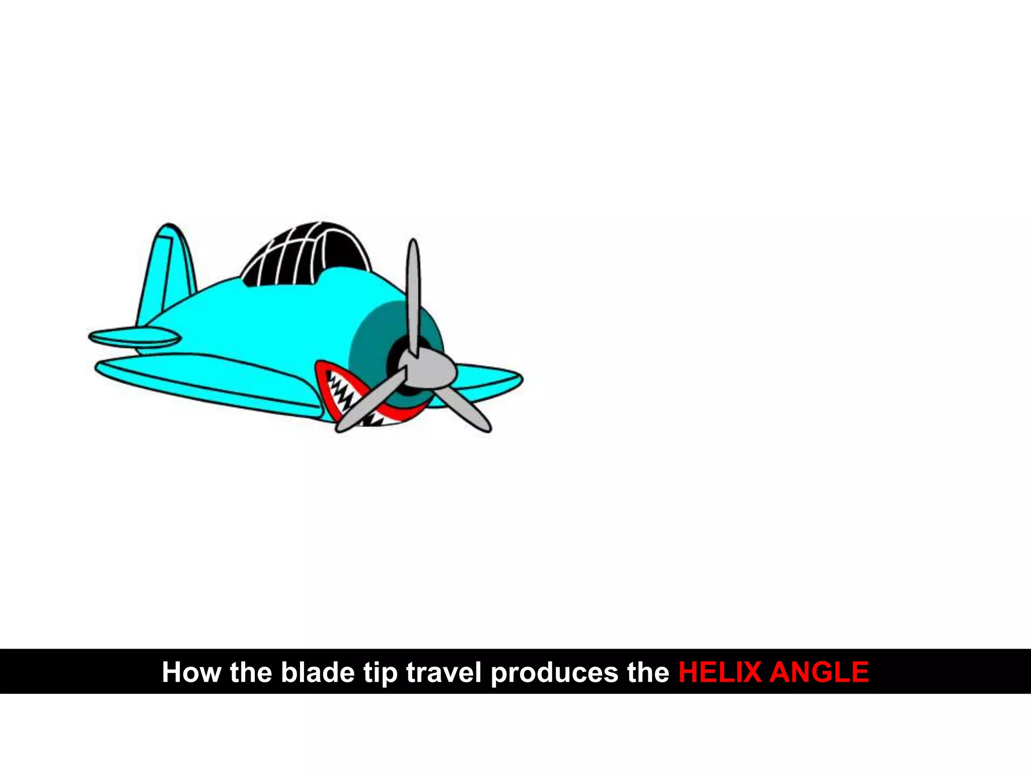
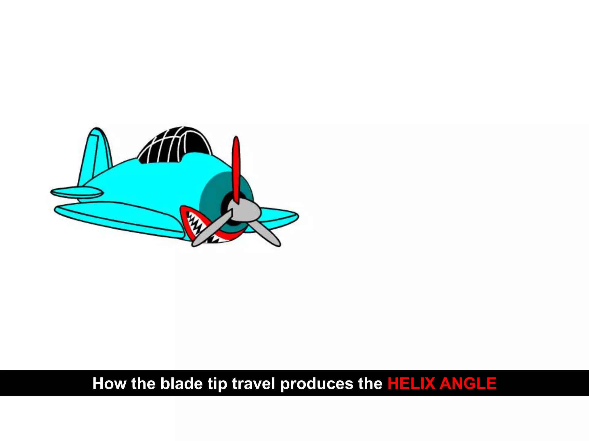
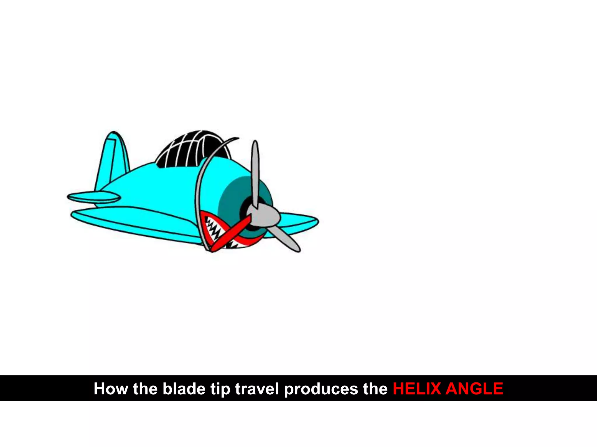
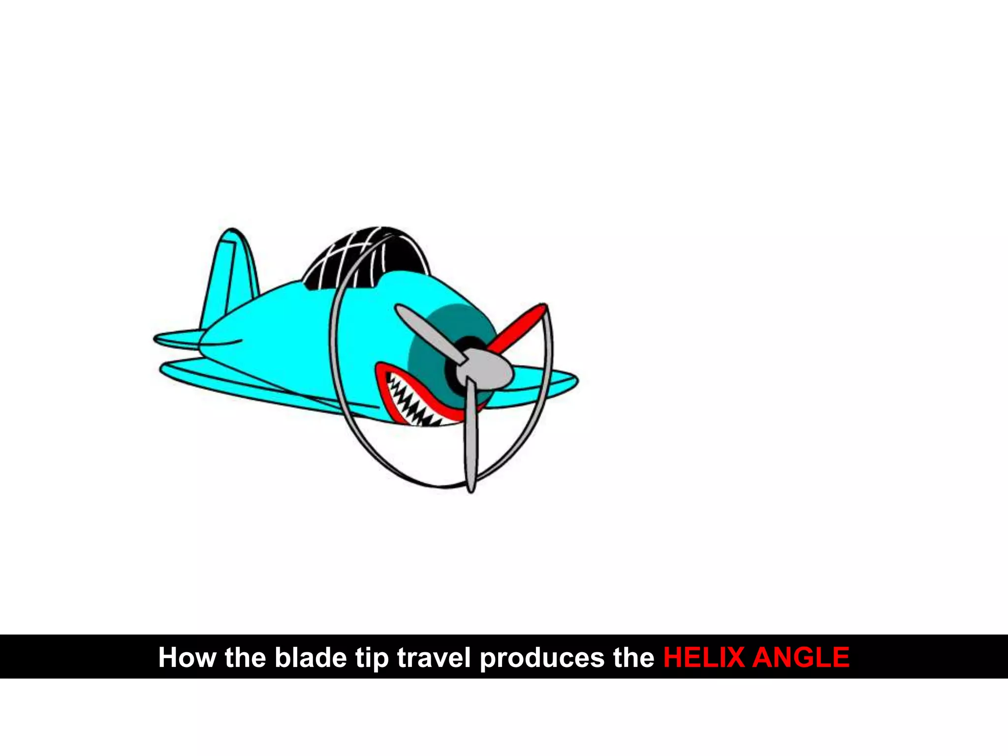
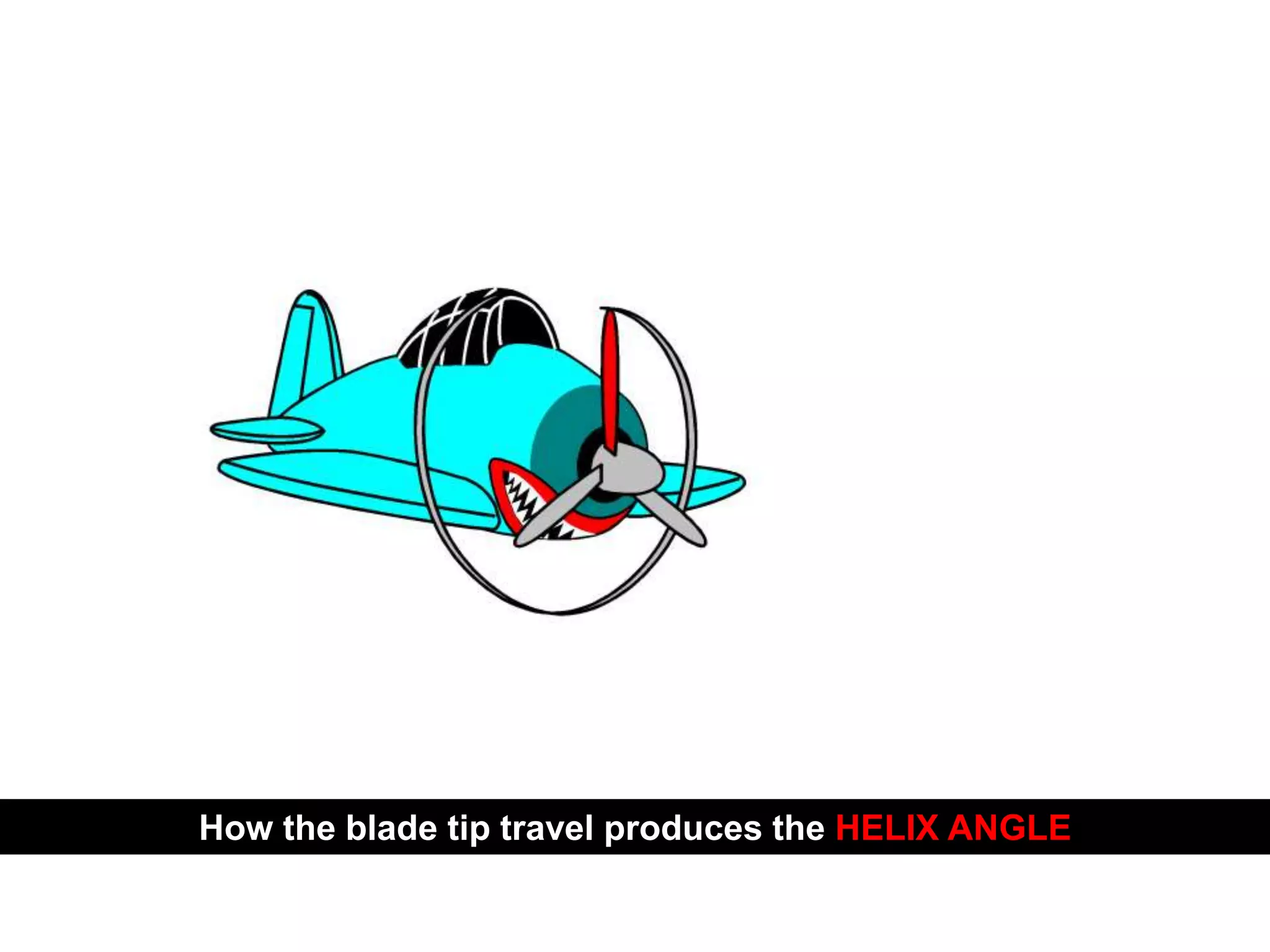
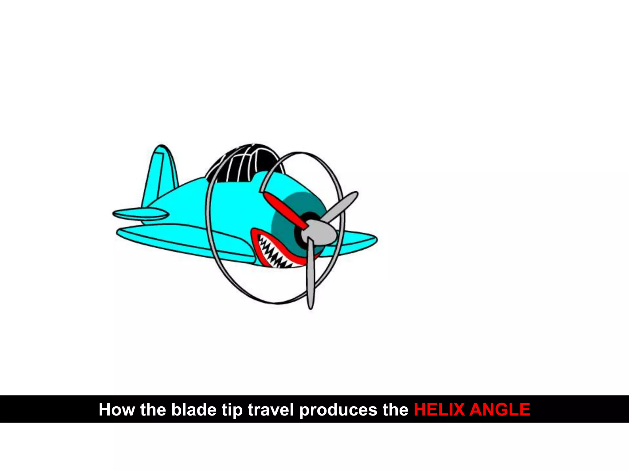
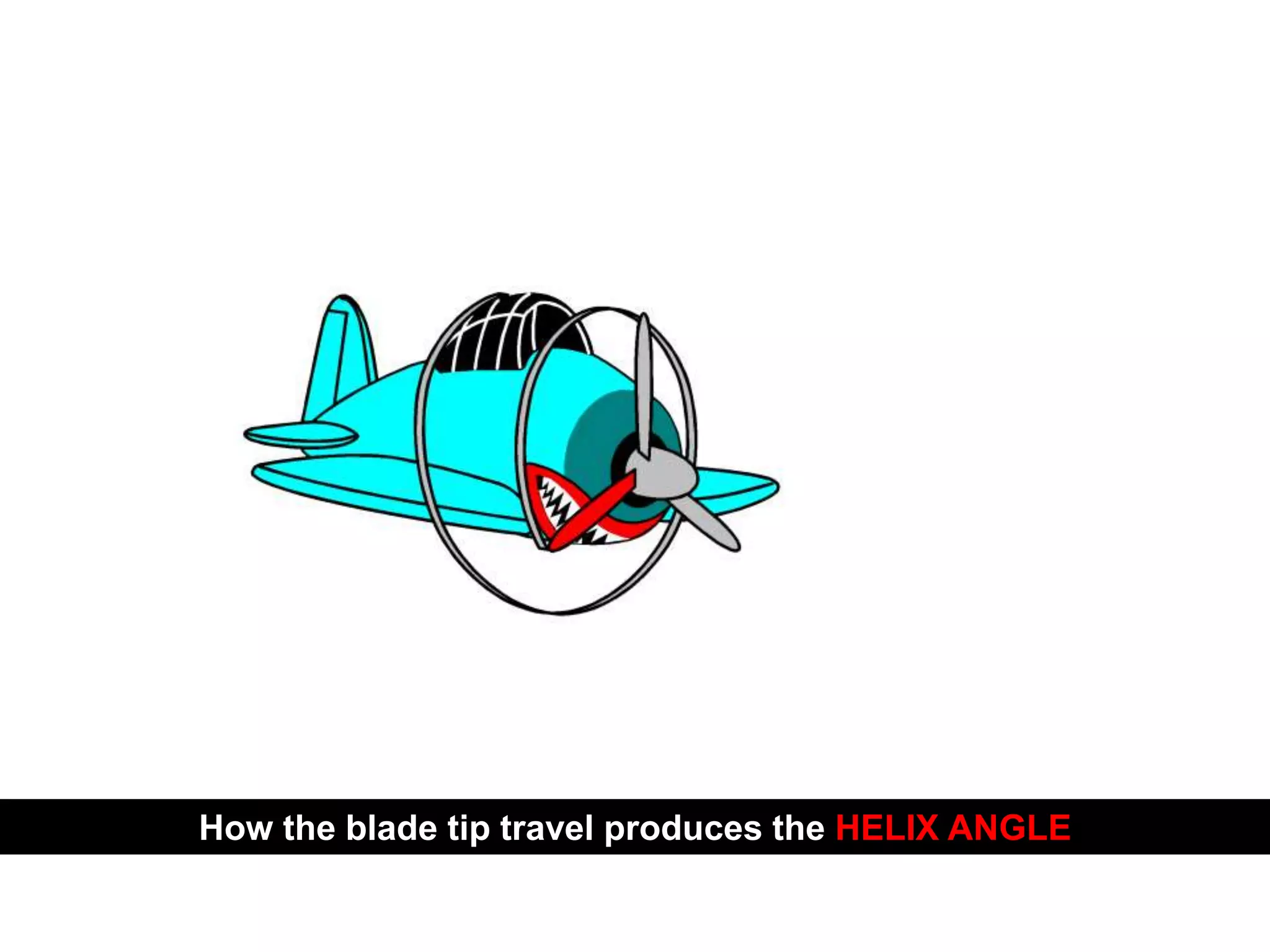
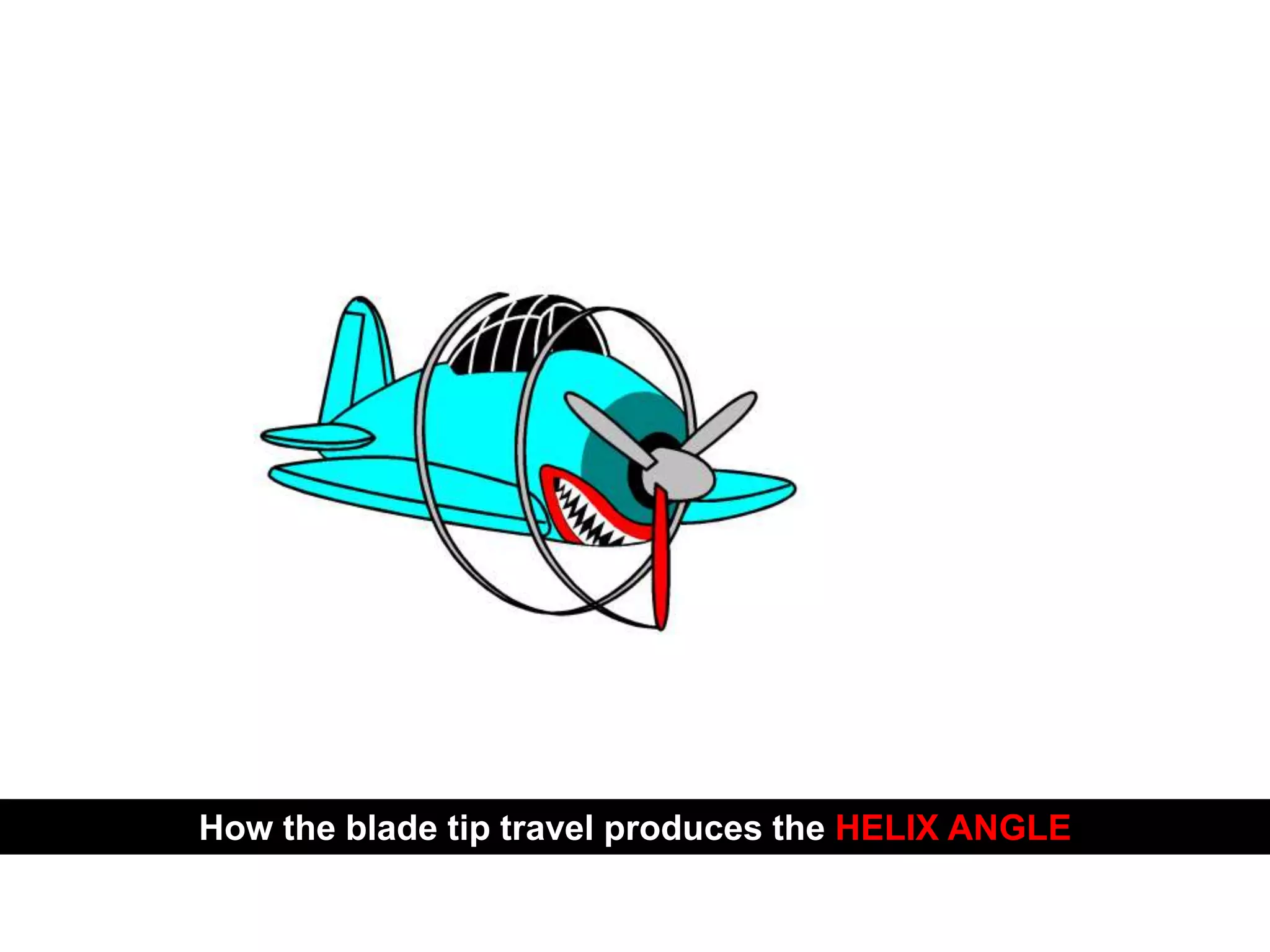
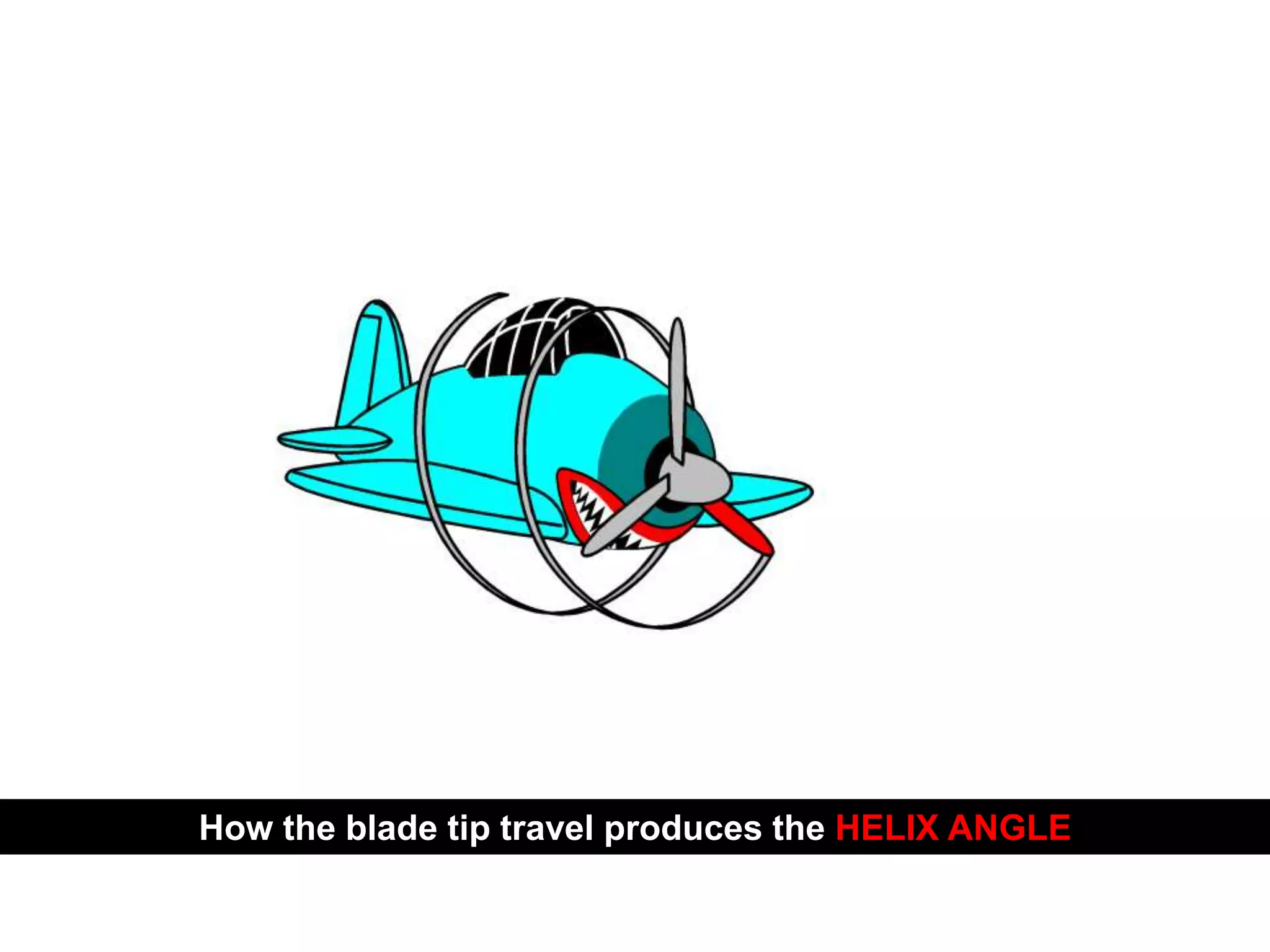
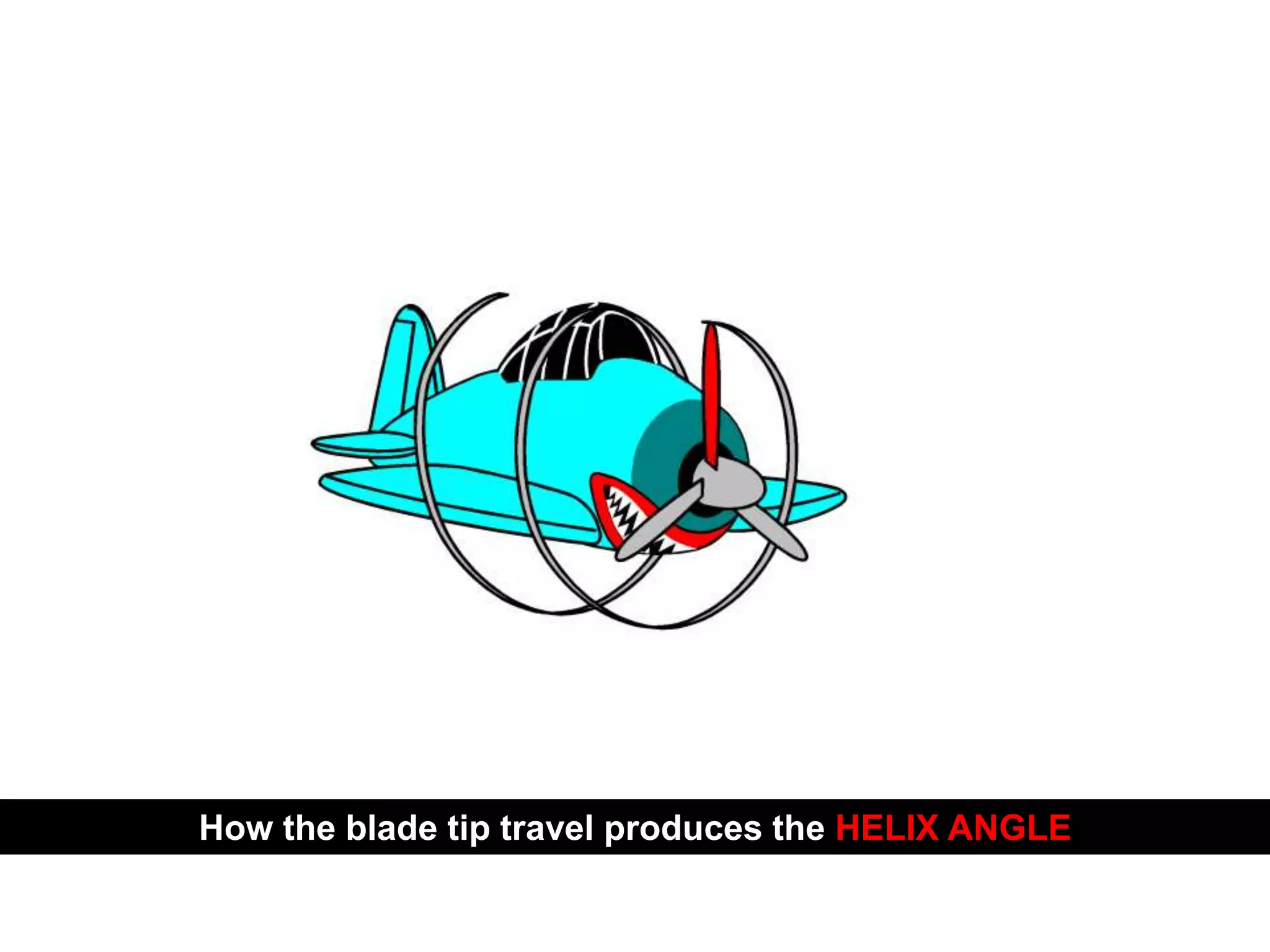
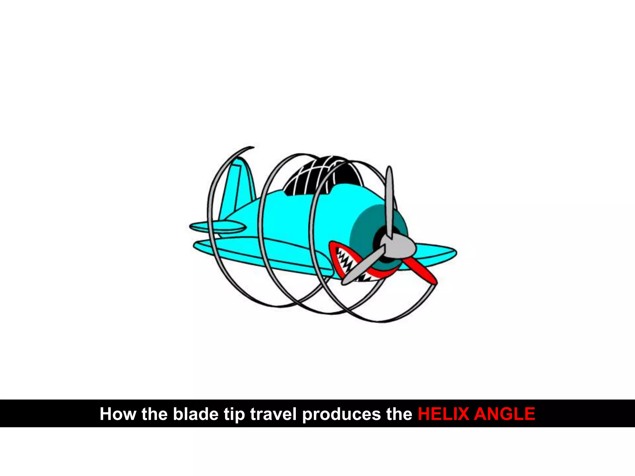
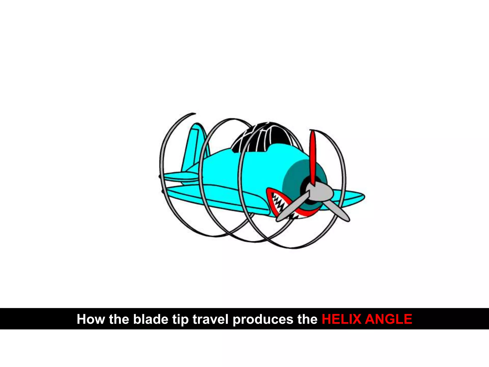
When a propeller spins and the aircraft moves forward, the tips of the
propeller blades move in a ‘corkscrew’ path
This path is called a HELIX
PROPELLER SYSTEM
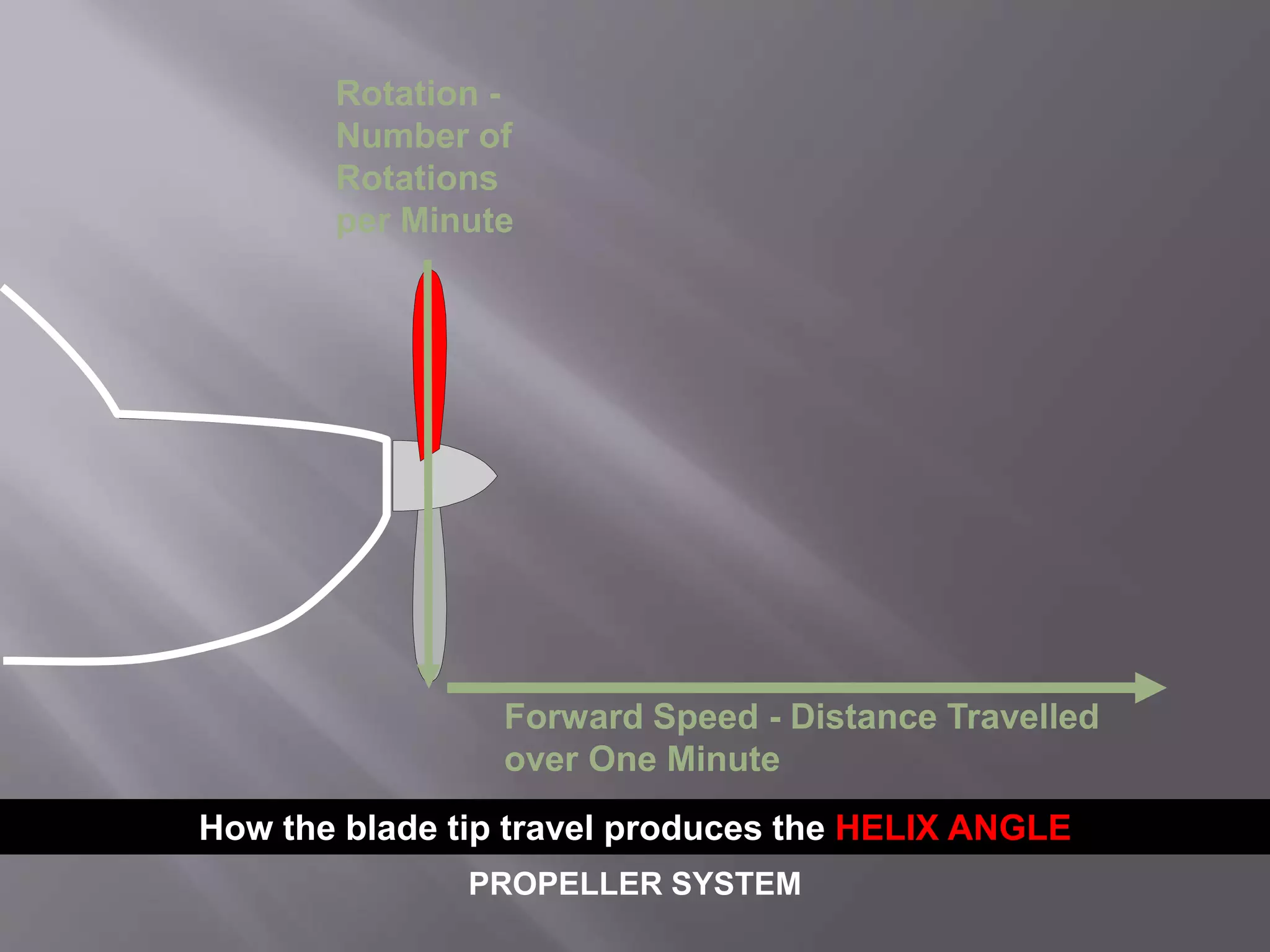
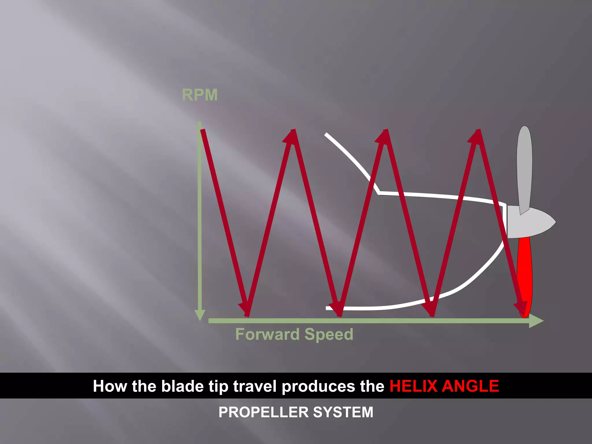
How the bladetip travel produces the HELIX ANGLE
PROPELLER SYSTEM
Forward Speed - Distance Travelled
over One Minute
Rotation -
Number of
Rotations
per Minute
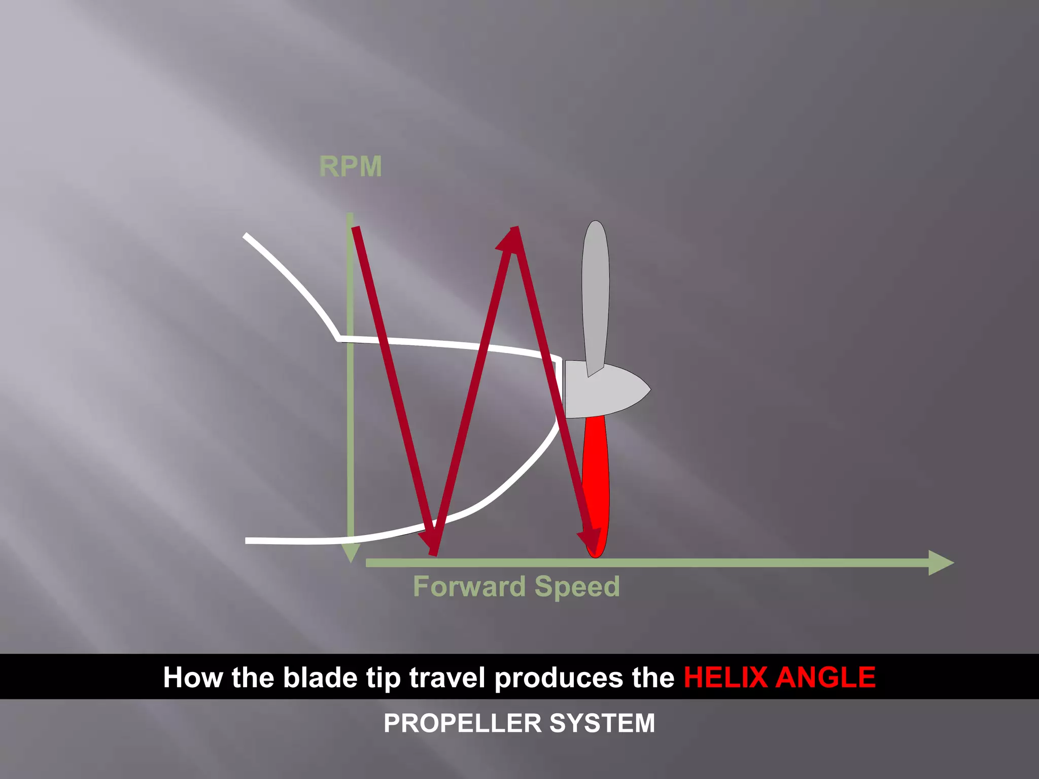
How the HELIXANGLE is changed by engine rpm and forward speed
63.
Forward Speed
RPM
How anincrease in RPM changes the Helix Angle
Changes in FORWARD SPEED and RPM will change the Helix Angle
Faster
RPM
PROPELLER SYSTEM
How the blade tip travel produces the HELIX ANGLE
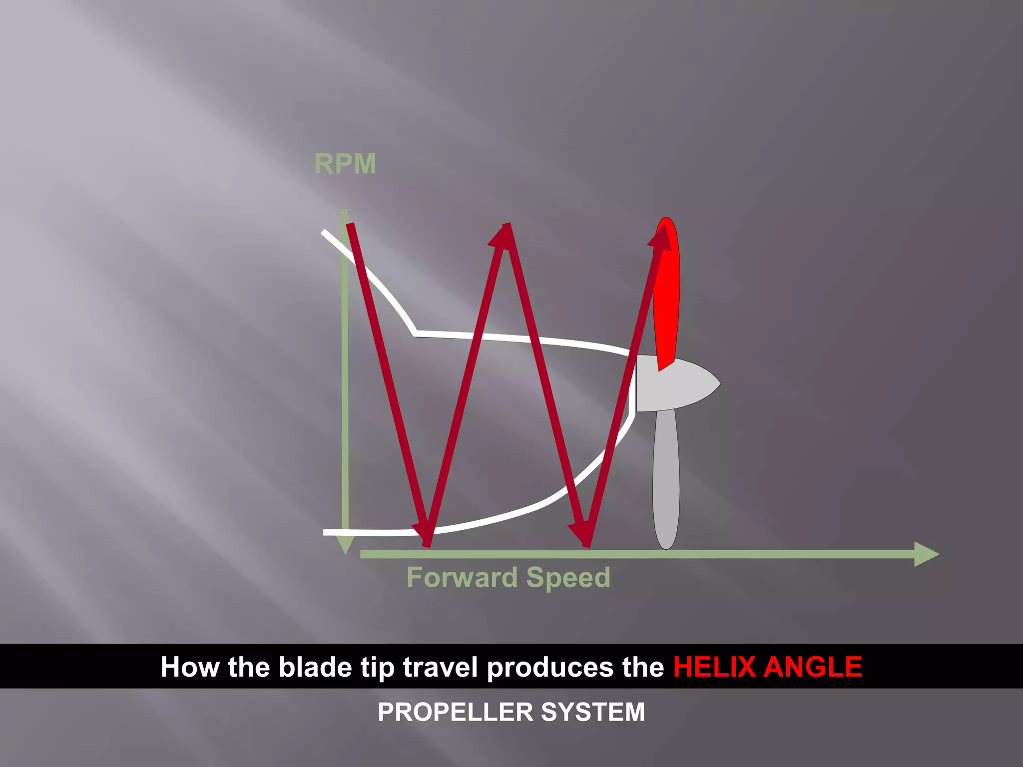
64.
Forward Speed
RPMRPM
Faster ForwardSpeed
Changes in FORWARD SPEED and RPM will change the Helix Angle
How an increase in FORWARD SPEED changes the HELIX ANGLE
PROPELLER SYSTEM
65.
Let’s take acloser look at the blade aerofoil and the Helix Angle and
thrust (lift) generation
If the Helix Angle changes,
then we need to change the
blade angle.
Remember (from the comparison with the aircraft wing), the optimum
Angle of Attack is required to maintain most efficient thrust generation.
This is the Helix Angle
This is the
Angle of
AttackDirection of
rotation
Direction of blade through
the air with forward speed
PROPELLER SYSTEM
All propeller bladesare actuated by the same mechanical linkage
PROPELLER SYSTEM
Sliding Piston
Hard Stops
Fine
Pitch
Coarse
Pitch
Direction
of
Rotation
Direction
of Flight
Propeller
Blade
Actuating
Lever
Actuating
Link
68.
Note: - bladeangle is relative to piston travel
Fine pitch
Coarse pitch
Or
‘Feathered’
Piston travels between ‘hard’ stops
Direction
Of
Rotation
Maximum resistance
to rotation
Minimum
resistance
to forward
speed
Minimum
resistance to
rotation
Maximum
resistance
to forward
speed
The blade angle changes through 90deg
with piston travel
At this hard stop
the blade is in
this position
At this hard stop
the blade is in
this position
PROPELLER SYSTEM
69.
Easier Starting ofengine
Direction of travel
Direction of
Rotation
Good for:-
Running engine with no/minimal thrust
Bad for:-
In-flight – loss of control
High drag – braking effect on ground
Zero pitch – or Ground Fine Pitch
In-flight engine failure – loss of control and
engine disintegration
PROPELLER SYSTEM
Importance of set blade angle
Fine pitch
Minimum
resistance to
rotation
Maximum
resistance
to forward
speed
70.
Maximum resistance
to rotation
Minimum
resistance
toforward
speed
Starting of engine
Direction of travel
Direction of
Rotation
Bad for:-
Could cause engine burn-out if running
Low drag – NO braking effect on ground
Maximum pitch – or Feathered
Good for:-
In-flight – loss of control
In-flight engine failure – control maintained
and engine stops
rotating minimizing
damage
PROPELLER SYSTEM
Importance of set blade angle
71.
Minimal
resistance to
rotation
Air pushed
forwardgiving
reverse thrust
Direction of travel
Direction of
Rotation
Used for:-
Bad for:-
In-flight – loss of forward speed, aircraft stalls
High drag – high braking effect on ground
Reverse Pitch
In-flight engine failure – loss of control and
reverse rotation
increasing
engine disintegration
Usually for military
aircraft only
PROPELLER SYSTEM
Importance of set blade angle
72.
Direction of travel
Directionof
Rotation
Used for:-
Low drag on final approach
Flight Fine and Cruise Pitch
Used for:-
In-flight descent – faster forward speed than
final approach
Flight
Fine
pitch
Cruise
pitch
Both give minimal drag at
low power settings
PROPELLER SYSTEM
Importance of set blade angle
DISTANCE TRAVELLED BY
ROOT,MID-SPAN AND TIP
THICK FOR
STRENGTH
PROPELLER SYSTEM
Blade Twist
ROOT MID-SPAN TIP
THINNER FOR
STRENGTH AND
THRUST
THIN FOR
THRUST
COARSE
ANGLE
MEDIUM
ANGLE
FINE
ANGLE
BLADE ANGLE RELATIVE TO DISTANCE (AND THEREFORE SPEED)
TRAVELLED BY ROOT, MID-SPAN AND TIP
Typical Blade
Typical 3
Blade Prop
75.
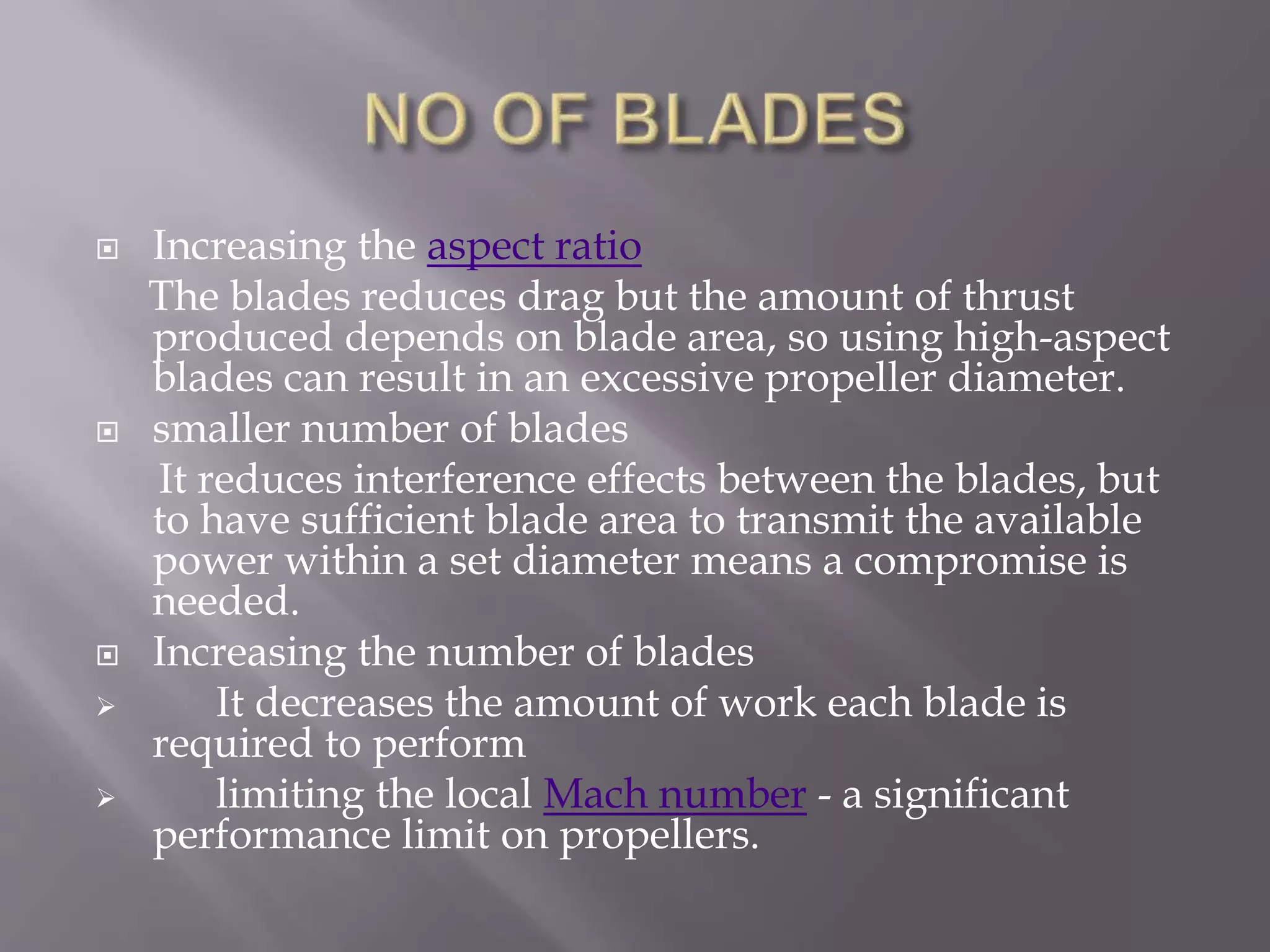
Increasing theaspect ratio
The blades reduces drag but the amount of thrust
produced depends on blade area, so using high-aspect
blades can result in an excessive propeller diameter.
smaller number of blades
It reduces interference effects between the blades, but
to have sufficient blade area to transmit the available
power within a set diameter means a compromise is
needed.
Increasing the number of blades
It decreases the amount of work each blade is
required to perform
limiting the local Mach number - a significant
performance limit on propellers.
76.
A propeller'sperformance suffers as the blade
speed nears the transonic.
As the relative air speed at any section of a
propeller is a vector sum of the aircraft speed
and the tangential speed due to rotation
propeller blade tip will reach transonic speed
well before the aircraft does.
propeller's performance transonic speed
77.
When theairflow over the tip of the blade
reaches its critical speed, drag and torque
resistance increase rapidly and shock waves
form creating a sharp increase in noise.
Aircraft with conventional propellers,
therefore, do not usually fly faster than Mach
0.6.
There have been propeller aircraft which
attained up to the Mach 0.8 range, but the low
propeller efficiency at this speed makes such
applications rare.
78.
The 'fix'is similar to that of transonic wing
design. The maximum relative velocity is kept
as low as possible by careful control of pitch to
allow the blades to have large helix angles; thin
blade sections are used and the blades are swept
back in a scimitar shape (Scimitar propeller).
The propellers designed are more efficient than
turbo-fans and their cruising speed (Mach 0.7–
0.85) is suitable for airliners, but the noise
generated is tremendous (see the Antonov An-
70 and Tupolev Tu-95 for examples of such a
design).
79.
Thrust bendingforce
Centrifugal and aerodynamic twisting forces
Centrifugal force
Torque bending force
80.
Early pitchcontrol settings were pilot operated, either
with a small number of preset positions or
continuously variable.
Following World War I, automatic propellers were
developed to maintain an optimum angle of attack.
This was done by balancing the centripetal twisting
moment on the blades and a set of counterweights
against a spring and the aerodynamic forces on the
blade.
Automatic props had the advantage of being simple,
lightweight, and requiring no external control, but a
particular propeller's performance was difficult to
match with that of the aircraft's powerplant.
81.
On somevariable-pitch propellers, the blades
can be rotated parallel to the airflow to reduce
drag in case of an engine failure. This uses the
term feathering,
On single-engined aircraft, whether a powered
glider or turbine-powered aircraft, the effect is
to increase the gliding distance.
On a multi-engine aircraft, feathering the
propeller on a failed engine helps the aircraft to
maintain altitude with the reduced power from
the remaining engines.
82.
In someaircraft, such as the C-130 Hercules, the
pilot can manually override the constant-speed
mechanism to reverse the blade pitch angle, and
thus the thrust of the engine (although the rotation
of the engine itself does not reverse).
This is used to help slow the plane down after
landing in order to save wear on the brakes and
tires, but in some cases also allows the aircraft to
back up on its own - this is particularly useful for
getting floatplanes out of confined docks. See
also Thrust reversal.
Activity factor(AF) is a design parameter
associated with the propeller blade’s geometry.
The more slender the blade (larger radius,
smaller chord), the lower the AF value:
xx
d
c
AF
hx p
d
16
100000 3
1
pd
c
AF 1563
Typically see higher AF props on turboprop engines.
86.
Each propellermust have a type certificate.
Engine power and propeller shaft rotational
speed may not exceed the limits for which the
propeller is certificated.
Each featherable propeller must have a means
to unfeather it in flight.
The propeller blade pitch control system must
meet the requirements of §§35.21, 35.23, 35.42
and 35.43 of this chapter.
87.
All areasof the airplane forward of the pusher
propeller that are likely to accumulate and
shed ice into the propeller disc during any
operating condition must be suitably protected
to prevent ice formation, or it must be shown
that any ice shed into the propeller disc will not
create a hazardous condition.
Each pusher propeller must be marked so that
the disc is conspicuous under normal daylight
ground conditions.
88.
If theengine exhaust gases are discharged into
the pusher propeller disc, it must be shown by
tests, or analysis supported by tests, that the
propeller is capable of continuous safe
operation.
All engine cowling, access doors, and other
removable items must be designed to ensure
that they will not separate from the airplane
and contact the pusher propeller.
89.
This sectiondoes not apply to fixed-pitch wood
propellers of conventional design.
The applicant must determine the magnitude of the
propeller vibration stresses or loads, including any stress
peaks and resonant conditions, throughout the
operational envelope of the airplane by either:
(1) Measurement of stresses or loads through direct
testing or analysis based on direct testing of the propeller
on the airplane and engine installation for which
approval is sought.
(2) Comparison of the propeller to similar propellers
installed on similar airplane installations
(b) The applicant must demonstrate by tests, analysis
based on tests, or previous experience on similar designs
that the propeller does not experience harmful effects of
flutter throughout the operational envelope of the
airplane.
90.
(c) Theapplicant must perform an evaluation of the
propeller to show that failure due to fatigue will be
avoided throughout the operational life of the propeller
using the fatigue and structural data obtained in
accordance with part 35 of this chapter and the vibration
data obtained from compliance with paragraph (a) of this
section.
The propeller includes the hub, blades, blade retention
component and any other propeller component whose
failure due to fatigue could be catastrophic to the
airplane. This evaluation must include:
(1) The intended loading spectra including all reasonably
foreseeable propeller vibration and cyclic load patterns,
identified emergency conditions, allowable overspeeds
and overtorques, and the effects of temperatures and
humidity expected in service.
(2) The effects of airplane and propeller operating and
airworthiness limitations.
91.
Unless smallerclearances are substantiated, propeller
clearances, with the airplane at the most adverse combination
of weight and center of gravity, and with the propeller in the
most adverse pitch position, may not be less than the
following:
(a) Ground clearance. There must be a clearance of at least seven
inches (for each airplane with nose wheel landing gear) or nine
inches (for each airplane with tail wheel landing gear) between
each propeller and the ground with the landing gear statically
deflected and in the level, normal takeoff, or taxing attitude,
whichever is most critical.
In addition, for each airplane with conventional landing gear
struts using fluid or mechanical means for absorbing landing
shocks, there must be positive clearance between the propeller
and the ground in the level takeoff attitude with the critical tire
completely deflated and the corresponding landing gear strut
bottomed. Positive clearance for airplanes using leaf spring
struts is shown with a deflection corresponding to 1.5g.
92.
(b) Aft-mountedpropellers.
An airplane with an aft mounted propeller
must be designed such that the propeller will
not contact the runway surface when the
airplane is in the maximum pitch attitude
attainable during normal takeoffs and landings.
(c) Water clearance.
There must be a clearance of at least 18 inches
between each propeller and the water, unless
compliance with §23.239 can be shown with a
lesser clearance.
93.
(d) Structuralclearance. There must be—
(1) At least one inch radial clearance between
the blade tips and the airplane structure, plus
any additional radial clearance necessary to
prevent harmful vibration;
(2) At least one-half inch longitudinal clearance
between the propeller blades or cuffs and
stationary parts of the airplane; and
(3) Positive clearance between other rotating
parts of the propeller or spinner and stationary
parts of the airplane.