Download to read offline


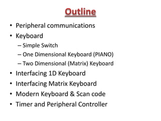
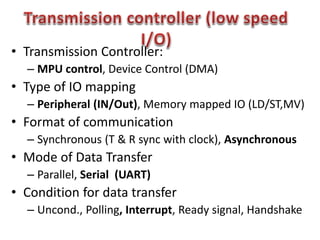
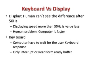
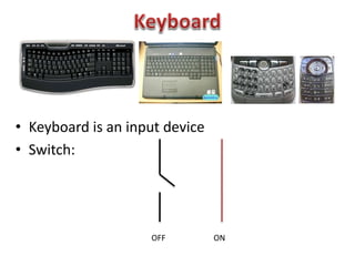
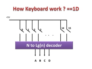
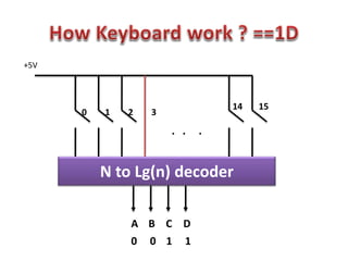
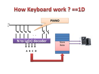
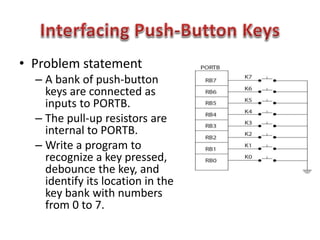
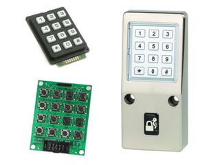
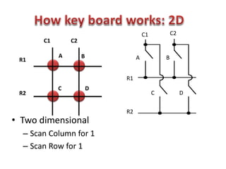
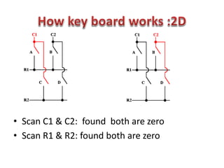
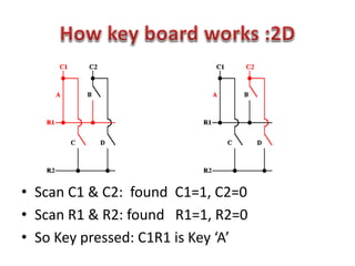
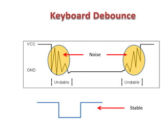
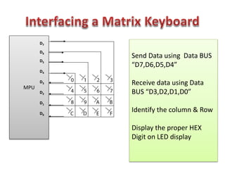
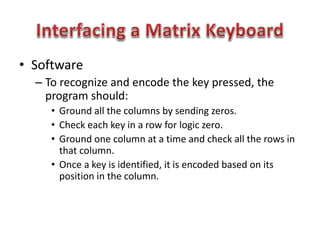
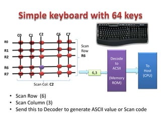
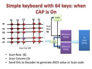
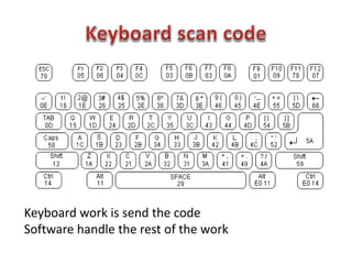
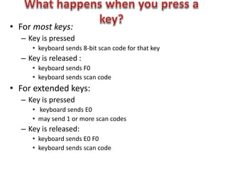
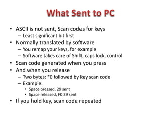
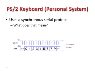
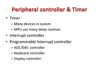


This document discusses keyboard interfacing and scanning techniques. It describes 1D and 2D keyboard layouts and interfacing methods. It discusses asynchronous and synchronous communication, interrupt-driven and polling-based I/O, and different types of I/O mapping such as memory-mapped and peripheral I/O. The document also covers keyboard encoding standards and scan codes, debouncing, and interfacing a basic keyboard matrix to a microprocessor.


![Ece iv-fundamentals of hdl [10 ec45]-notes](https://cdn.slidesharecdn.com/ss_thumbnails/ece-iv-fundamentalsofhdl10ec45-notes-150103114952-conversion-gate02-thumbnail.jpg?width=640&height=640&fit=bounds)


