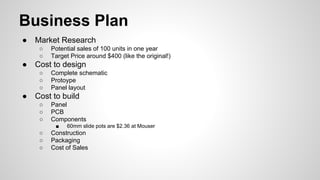
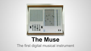
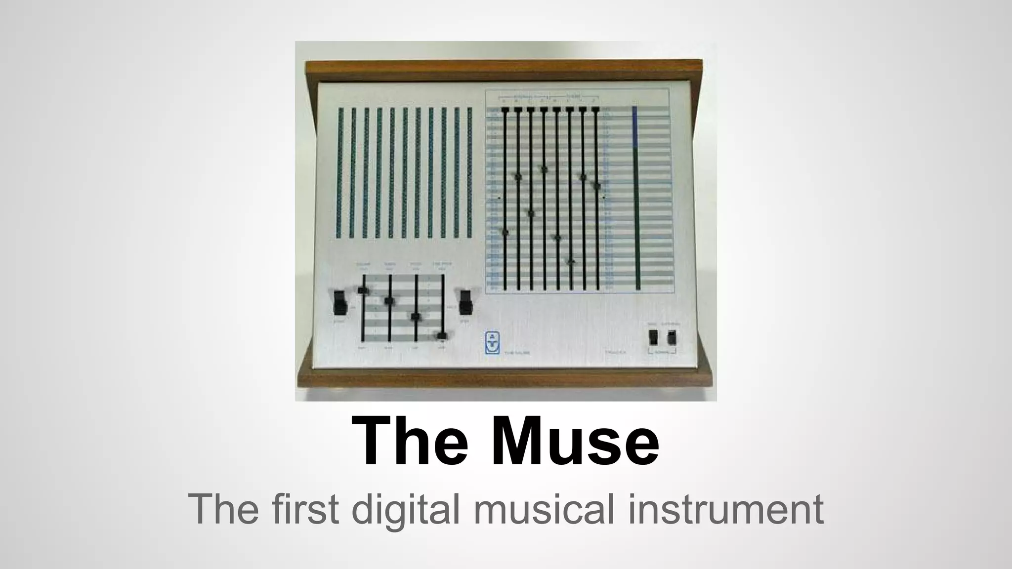
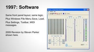
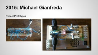
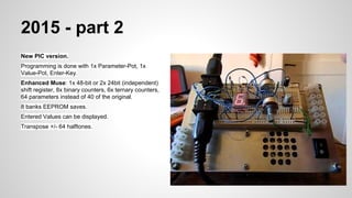
The Muse was the first digital musical instrument created in the 1960s. It used a shift register and counters to deterministically sequence notes based on user-controlled interval and pitch settings. Recent prototypes have updated the Muse concept with a microcontroller, expanded controls and feedback. There is potential to commercialize an Eurorack modular version that faithfully replicates the original hardware design and algorithm using modern components, while adding features like voltage control and digital position feedback. Initial market research estimates sales of 100 units at a target price of $400.
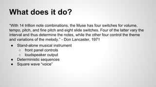
![Eurorack
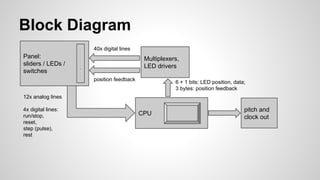
● Panel Inputs
○ Interval / Theme input: Eight 60mm slide pots: Bourns PTL60 series
○ Vol / Tempo / Pitch / Fine: Four 20mm slide pots
○ On / Off / Start: SPDT [On-Off-Momentary]
○ Auto / Hold / Step: SPDT [On-Off-Momentary]
○ Rest
● Panel Display
○ 40 LEDs for counters and shift register
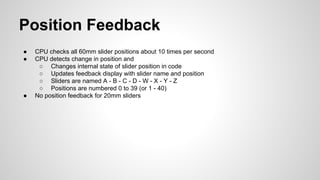
○ New: 3 character alphanumeric display for slider position feedback
● Microcontroller core
○ A to D for Interval / Theme inputs
○ LED drive via multiplex
● Voltage Control
○ Tempo, Pitch, Start, Reset
● Voltage Outputs
○ Pitch encoded as voltage
○ Audio
○ Tempo Clock](https://image.slidesharecdn.com/cee8b834-2c89-41e1-9dd7-52fdd16b87cb-150917130601-lva1-app6891/85/Triadex-Muse-11-320.jpg)