SlideShare a Scribd company logo
1 of 48
Download to read offline
What is One Wire Serial Communication
● Serial data transmission over one wire(duh)
● Great for cheap applications that don't require high speed data transfer
● In theory, all AVR processors can handle One Wire Communication
● Timing is extremely important
○ The only way to discern signals from other signals
How Does it Work?
● Two basic implementations
○ Polled Implementations(software only)
○ Interrupt driven (counter required)
● Dallas 1-Wire Protocol
○ Designed by the Dallas Semiconductor Corporation
○ Can use either interrupt driven or polled implementations
○ Polled requires no external hardware
○ Half Duplex(transmitting or receiving not Both simultaneously)
Dallas 1-Wire
● Signal is idle High, need pull up resistor
● Signaling is divided into time slots of 60µs
● Master initiates every communication
○ Regardless of direction
● 5 basic signals: (Write 1, Write 0, Read, Reset, Presence)
● LSB sent first
Overall Communication process
All 1-Wire devices follow this basic sequence:
1. The Master sends the Reset pulse.
2. The Slave(s) respond with a Presence pulse.
3. Master sends a ROM command
4. Master sends a Memory command
How To Send Bits
● In order to send bits in OW protocol it requires precise timing and precise
waveforms
● Errors in these waveforms, or the timing can deliver corrupt data and
requires digital error checking
Bus Signals
● Write 1
○ The Master pulls the bus low for 15µs then releases for
remainder of 60µs window
Bus Signals Continued
● Write 0
○ The master pulls the bus low for 60µs
● Read
○ Master pulls bus low for 1 to 15µs
○ The slave then releases the line if it wants to write 1 or keeps
the line low for write 0 for remainder of 60 us window.
Timing Diagram of OW Signals
Reset/Presence Signal
● Reset Signal
○ The master pulls the line low for 480µs and then releases it
○ If slave is present then the presence signal should be seen
○ If no presence signal is detected there is no device connected
● Presence Signal
○ After the Reset Signal has been sent it is the slave that must pull the line
low for 60µs
○ Must pull the line low within 60µs
Reset Presence Signal Waveform
Generating Signals through Software
● Define delay values
● Define our BUS pin
● Initialize the bus as an output
Structure of delayMicroseconds function
One Wire Write function
C++ One Wire Write function
One Wire Read Function
C++ One Wire Read Bit Function
One Wire Reset/Presence Signal
C++ One Wire Reset/Presence Signal
Generating the Signals
● Software Only
○ Simply changing the direction and value of a GPIO and generating
required delay is sufficient
● With UART
○ Requires both TXD and RXD pins to be connected to the bus
○ Need tri-state or open-collector buffer so the slave can pull the
line low.
IC for UART Signals
DM74LS126A Tri-state Buffer IC
Generating UART Signals
● Baud rate is equivalent to bits/sec
● In order to transmit 1-wire framed data from UART platform we must
frame the data into the same time slots as in the polled implementation
● One UART data frame is used to generate one waveform bit of 1 wire data
or one RESET/Presence signal
Framing 1-Wire from UART
● To match waveform UART data
frame must match 1-Wire data
frame
● All UART signals initiate with a start
bit “0” or LOW
● To “Write 1” in one wire format all
bits in UART Frame after Start bit
must be HIGH or “1”
● To “Write 0” all bits in UART data
frame are “0” or LOW
● Stop bit is always HIGH or “1”
● “Read 1” Start bit is LOW and slave
writes bit “1” or HIGH in the
remaining data bits in UART frame
● “Read 0” start bit is LOW and the
slave drives the bus low by writing
“0” to the rest of the UART bit
pattern and drives the bus HIGH for
the STOP bit.
Generating One Wire Frame From UART
Reset/Presence Signal with UART
● UART bits 0-3 are LOW, 4 is HIGH, and Slave writes UART bits 5,6,&7
LOW
● Stop bit for this signal is HIGH
Overall Communication process
All 1-Wire devices follow this basic sequence(MUST FOLLOW):
1. The Master sends the Reset pulse.
2. The Slave(s) respond with a Presence pulse.
3. Master sends a ROM command
4. Master sends a Memory command
ROM Commands
● All 1-Wire devices contain a 64 bit identifier stored in ROM
● ROM Commands address those 64 bit identifiers
● After bus master detects a presence pulse it can issue a ROM command to
detect how many slaves are on the bus, and which slave to address.
ROM Commands MAX31820
● Read ROM(33h)-Reads the ROM code of single slave device. If there are
multiple slave devices and the command is issued, data collision will occur.
● Skip ROM(CCh)-Sends data for addressing to all connected slave devices
● Match ROM(55h)-Is used to address individual slave devices on the bus
● Search ROM(F0h)-Is used to get the ID of slave devices if not known
Cyclic Redundancy Check
● CRC is used an every ROM command to check for data integrity.
● CRC - is an error detection code for digital networks.
● It sends a check value along with the data that is transmitted. This value is
determined by dividing the data by a nominal value and returning the
remainder.
● If once the data is received and the remainder value is not the same, after
the received data has been divided by the nominal value, then we know the
data has been corrupted.
How CRC works
● We can think of CRC as an 8 bit shift register with feedback
How CRC Works
● At the beginning of a 64 bit Read ROM command the CRC shift register has
an initial value of zero. CRC = 0x00
● The LSB of the 64 bit identifier is XORd with the LSB of the input data. In the
case of 64 bit identifiers the LSB is a family CRC code(ex: 0xA2). So after the
first byte of data has been processed the CRC register will contain the value
of the CRC code. CRC = 0xA2
● After the entire 64 bit identifier has been shifted into and out of the CRC
register the register should have a final value of 0x00 if no data was
corrupted. If data was corrupted we would have a value inside the CRC shift
register and the data would have to be retransmitted.
CRC Computation of 1-Wire(Look up Table)
1. Dallas Semiconductor Corp. provides a table for CRC calculations. This table
rapidly increase CRC calculations and can process entire bytes of data per
loop run.
2. CRC register is initially zero we then shift in the first byte of 64 bit ID into
register
3. Then we XOR the next byte of data with the CRC register
4. Using pgm_read_byte we point to the index of our table and set our CRC
register to that new value. We are indexing by the XORd value of the CRC
register and the input data.
5. We repeat steps 4 and 5 until we are done with all 64 bits or 8 bytes of our
ID.
6. If CRC is 0 then no data was corrupted else data has been corrupted.
CRC Function Code Example
CRC Look Up Method
This table shows how each byte of data gets shifted into our CRC register and how we
calculate the next index for our CRC value.
Overall Communication process
All 1-Wire devices follow this basic sequence(MUST FOLLOW):
1. The Master sends the Reset pulse.
2. The Slave(s) respond with a Presence pulse.
3. Master sends a ROM command
4. Master sends a Memory command
Memory Commands
● Are commands specific to slave devices or a class of devices
● They deal with the internal memory and registers of slave devices
● Therefore for each device memory commands are specific to that device
MAX31820 Memory Registers
● Memory commands specific to this device would address this device's internal memory
registers
● TH and TL would address BYTE 2 and BYTE 3 of the temperature sensors internal
scratchpad memory
MAX31820 - Ambient Temperature
Sensor
MAX31820 Configuration Registers
● Bits R1 and R0 control the resolution of the temperature reading
● Better resolution slower conversion time, and faster conversion time less
resolution
MAX31820 Function Command Set
Overall Communication process
All 1-Wire devices follow this basic sequence:
1. The Master sends the Reset pulse.
2. The Slave(s) respond with a Presence pulse.
3. Master sends a ROM command
4. Master sends a Memory command
1 Wire Digital Temperature Sensor Implementation
● Assemble this simple circuit, the resistor is needed for the idle state of the
bus(HIGH)
● Also because it will act as a pull up resistor
Step 1
Download Necessary Libraries
Step 2
● Download OneWire Arduino Library
● Download DallasTemperature Arduino
Library
● Place both libraries into your Arduino
library path
● Include both libraries in your C++ code
1 Wire Digital Temperature Sensor Implementation
Step 3 Arduino Code
OneWire and DallasTemperature functions
● OneWire oneWire(ONE_WIRE_BUS) - this is a data structure defined in the one
wire library
● DallasTemperature sensors(&oneWire) - this is another data structure defined in
the DallasTemperature library that is an array of 8 bytes.(that is why the structure
must be passed as a pointer)
OneWire and DallasTemperature functions
● sensors.begin - is a subroutine in the DallasTemperature library that
identifies the type of temperature sensor on the bus and initializes the type
of power supply the temperature sensors requires.
● sensors.requestTemperatures - sends a reset/presence signal to begin
communication with device. Once presence is detected skip ROM command
is sent because only one temperature sensor is on the bus. Then we issue a
memory command that begins to send data of the temperature back to the
master device.
● sensors.getTempCByIndex(0) - This function returns the temperature in
celsius detected by the temperature sensor. If device is disconnected
during process it will return “DEVICE_DISCONNECTED_C”.
OneWire and DallasTemperature functions
References
https://en.wikipedia.org/wiki/1-Wire
http://www.atmel.com/images/Atmel-2579-Dallas-1Wire-Master-on-tinyAVR-and-megaAVR_ApplicationNote_AVR318.pdf
https://www.maximintegrated.com/en/app-notes/index.mvp/id/126
https://forum.pjrc.com/threads/23939-Strange-behavior-on-the-Onewireslave-library?p=33608&viewfull=1#post33608
https://create.arduino.cc/projecthub/TheGadgetBoy/ds18b20-digital-temperature-sensor-and-arduino-9cc806
https://www.hacktronics.com/Tutorials/arduino-1-wire-address-finder.html
https://en.wikipedia.org/wiki/Cyclic_redundancy_check
https://www.maximintegrated.com/en/app-notes/index.mvp/id/27
https://www.maximintegrated.com/en/products/1-wire/flash/overview/
Questions
1. How long are the time divisions of each bit level command?
2. What is the Idle state of the bus line?
3. What are the types of implementations of one wire?
4. Which implementation requires external hardware?
5. How does the master know there is a slave device connected?
6. Where are the 64 bit IDs of connected devices stored?
7. Which signal takes more than 1 time slot to transmit?
8. What device is needed for one wire UART?
9. What is the waveform of the write 1 signal?
10. Can data be both transmitted and received simultaneously by the one wire
protocol?
Answers
1. 60 microseconds
2. HIGH
3. Polled, UART(interrupt driven)
4. UART
5. Presence signal
6. ROM
7. Reset/Presence Signal
8. Tri-state buffer
9. Draw
10. No

More Related Content

What's hot

Introduction to arm processor
Introduction to arm processorIntroduction to arm processor
Introduction to arm processorRAMPRAKASHT1
 
Embedded Systems (18EC62) - ARM Cortex-M3 Instruction Set and Programming (Mo...
Embedded Systems (18EC62) - ARM Cortex-M3 Instruction Set and Programming (Mo...Embedded Systems (18EC62) - ARM Cortex-M3 Instruction Set and Programming (Mo...
Embedded Systems (18EC62) - ARM Cortex-M3 Instruction Set and Programming (Mo...Shrishail Bhat
 
Arm Processors Architectures
Arm Processors ArchitecturesArm Processors Architectures
Arm Processors ArchitecturesMohammed Hilal
 
EEPROM Part-21
EEPROM Part-21EEPROM Part-21
EEPROM Part-21Techvilla
 
counter using 4 master slave flip-flops
counter using 4 master slave flip-flops counter using 4 master slave flip-flops
counter using 4 master slave flip-flops ZunAib Ali
 
Design for Testability DfT Seminar
Design for Testability DfT SeminarDesign for Testability DfT Seminar
Design for Testability DfT SeminarAccendo Reliability
 
Computer organization memory
Computer organization memoryComputer organization memory
Computer organization memoryDeepak John
 
Dual Core Processor
Dual Core ProcessorDual Core Processor
Dual Core Processorfaiza nahin
 
EE6008 MCBSD - Introduction to PIC Micro controller
EE6008 MCBSD - Introduction to PIC Micro controller EE6008 MCBSD - Introduction to PIC Micro controller
EE6008 MCBSD - Introduction to PIC Micro controller pavihari
 
An improvised design implementation of sram
An improvised design implementation of sramAn improvised design implementation of sram
An improvised design implementation of sramIAEME Publication
 
Pipelining and ILP (Instruction Level Parallelism)
Pipelining and ILP (Instruction Level Parallelism) Pipelining and ILP (Instruction Level Parallelism)
Pipelining and ILP (Instruction Level Parallelism) A B Shinde
 
An application of 8085 register interfacing with LED
An application  of 8085 register interfacing with LEDAn application  of 8085 register interfacing with LED
An application of 8085 register interfacing with LEDTaha Malampatti
 
ECEN Academy Embedded Systems Programming Jan2022 batch
ECEN Academy Embedded Systems Programming  Jan2022 batchECEN Academy Embedded Systems Programming  Jan2022 batch
ECEN Academy Embedded Systems Programming Jan2022 batchbalajeeseshadri
 
System on chip architectures
System on chip architecturesSystem on chip architectures
System on chip architecturesA B Shinde
 
Static and Dynamic Read/Write memories
Static and Dynamic Read/Write memoriesStatic and Dynamic Read/Write memories
Static and Dynamic Read/Write memoriesAbhilash Nair
 
Unit 1 Introduction to Embedded computing and ARM processor
Unit 1 Introduction to Embedded computing and ARM processorUnit 1 Introduction to Embedded computing and ARM processor
Unit 1 Introduction to Embedded computing and ARM processorVenkat Ramanan C
 

What's hot (20)

Introduction to arm processor
Introduction to arm processorIntroduction to arm processor
Introduction to arm processor
 
Embedded Systems (18EC62) - ARM Cortex-M3 Instruction Set and Programming (Mo...
Embedded Systems (18EC62) - ARM Cortex-M3 Instruction Set and Programming (Mo...Embedded Systems (18EC62) - ARM Cortex-M3 Instruction Set and Programming (Mo...
Embedded Systems (18EC62) - ARM Cortex-M3 Instruction Set and Programming (Mo...
 
Arm Processors Architectures
Arm Processors ArchitecturesArm Processors Architectures
Arm Processors Architectures
 
EEPROM Part-21
EEPROM Part-21EEPROM Part-21
EEPROM Part-21
 
counter using 4 master slave flip-flops
counter using 4 master slave flip-flops counter using 4 master slave flip-flops
counter using 4 master slave flip-flops
 
Design for Testability DfT Seminar
Design for Testability DfT SeminarDesign for Testability DfT Seminar
Design for Testability DfT Seminar
 
Question Bank Microprocessor 8085
Question Bank Microprocessor 8085Question Bank Microprocessor 8085
Question Bank Microprocessor 8085
 
Computer organization memory
Computer organization memoryComputer organization memory
Computer organization memory
 
Programmable Timer 8253/8254
Programmable Timer 8253/8254Programmable Timer 8253/8254
Programmable Timer 8253/8254
 
DDR2 SDRAM
DDR2 SDRAMDDR2 SDRAM
DDR2 SDRAM
 
Dual Core Processor
Dual Core ProcessorDual Core Processor
Dual Core Processor
 
EE6008 MCBSD - Introduction to PIC Micro controller
EE6008 MCBSD - Introduction to PIC Micro controller EE6008 MCBSD - Introduction to PIC Micro controller
EE6008 MCBSD - Introduction to PIC Micro controller
 
An improvised design implementation of sram
An improvised design implementation of sramAn improvised design implementation of sram
An improvised design implementation of sram
 
Pipelining and ILP (Instruction Level Parallelism)
Pipelining and ILP (Instruction Level Parallelism) Pipelining and ILP (Instruction Level Parallelism)
Pipelining and ILP (Instruction Level Parallelism)
 
presentation on SCB,DEBUG,RESET of Arm Cortex processor
presentation on SCB,DEBUG,RESET of Arm Cortex processorpresentation on SCB,DEBUG,RESET of Arm Cortex processor
presentation on SCB,DEBUG,RESET of Arm Cortex processor
 
An application of 8085 register interfacing with LED
An application  of 8085 register interfacing with LEDAn application  of 8085 register interfacing with LED
An application of 8085 register interfacing with LED
 
ECEN Academy Embedded Systems Programming Jan2022 batch
ECEN Academy Embedded Systems Programming  Jan2022 batchECEN Academy Embedded Systems Programming  Jan2022 batch
ECEN Academy Embedded Systems Programming Jan2022 batch
 
System on chip architectures
System on chip architecturesSystem on chip architectures
System on chip architectures
 
Static and Dynamic Read/Write memories
Static and Dynamic Read/Write memoriesStatic and Dynamic Read/Write memories
Static and Dynamic Read/Write memories
 
Unit 1 Introduction to Embedded computing and ARM processor
Unit 1 Introduction to Embedded computing and ARM processorUnit 1 Introduction to Embedded computing and ARM processor
Unit 1 Introduction to Embedded computing and ARM processor
 

Similar to One-Wire-Serial-Communication.pdf

Embedded systems and robotics by scmandota
Embedded systems and robotics by scmandotaEmbedded systems and robotics by scmandota
Embedded systems and robotics by scmandotascmandota
 
Digital logic-formula-notes-final-1
Digital logic-formula-notes-final-1Digital logic-formula-notes-final-1
Digital logic-formula-notes-final-1Kshitij Singh
 
I2 c and mpu6050 basics
I2 c and mpu6050 basicsI2 c and mpu6050 basics
I2 c and mpu6050 basicsironstein1994
 
Universal synchronous asynchronous receiver transmitter(usart) and AtoD Coverter
Universal synchronous asynchronous receiver transmitter(usart) and AtoD CoverterUniversal synchronous asynchronous receiver transmitter(usart) and AtoD Coverter
Universal synchronous asynchronous receiver transmitter(usart) and AtoD CoverterTejas Shetye
 
Training Report on embedded Systems and Robotics
Training Report on embedded  Systems and RoboticsTraining Report on embedded  Systems and Robotics
Training Report on embedded Systems and RoboticsNIT Raipur
 
communication interfaces-Embedded real time systems
communication interfaces-Embedded real time systemscommunication interfaces-Embedded real time systems
communication interfaces-Embedded real time systemsRaghunath reddy
 
Design and Fabrication of 4-bit processor
Design and Fabrication of  4-bit processorDesign and Fabrication of  4-bit processor
Design and Fabrication of 4-bit processorPriyatham Bollimpalli
 
Raspberry Pi - Lecture 3 Embedded Communication Protocols
Raspberry Pi - Lecture 3 Embedded Communication ProtocolsRaspberry Pi - Lecture 3 Embedded Communication Protocols
Raspberry Pi - Lecture 3 Embedded Communication ProtocolsMohamed Abdallah
 
Lect 3 ARM PROCESSOR ARCHITECTURE
Lect 3  ARM PROCESSOR ARCHITECTURE Lect 3  ARM PROCESSOR ARCHITECTURE
Lect 3 ARM PROCESSOR ARCHITECTURE Dr.YNM
 
Lecture 10 (serial communication)
Lecture 10 (serial communication)Lecture 10 (serial communication)
Lecture 10 (serial communication)cairo university
 
Micro c lab8(serial communication)
Micro c lab8(serial communication)Micro c lab8(serial communication)
Micro c lab8(serial communication)Mashood
 
PIC 16F877 micro controller by Gaurav raikar
PIC 16F877 micro controller by Gaurav raikarPIC 16F877 micro controller by Gaurav raikar
PIC 16F877 micro controller by Gaurav raikarGauravRaikar3
 
Industrial training report of embedded system and robotics
Industrial training report of embedded system and roboticsIndustrial training report of embedded system and robotics
Industrial training report of embedded system and roboticsPallavi Bharti
 
Computer System and Architecture
Computer System and ArchitectureComputer System and Architecture
Computer System and Architecturesarfraz1411
 

Similar to One-Wire-Serial-Communication.pdf (20)

Embedded systems and robotics by scmandota
Embedded systems and robotics by scmandotaEmbedded systems and robotics by scmandota
Embedded systems and robotics by scmandota
 
Assembler4
Assembler4Assembler4
Assembler4
 
Digital logic-formula-notes-final-1
Digital logic-formula-notes-final-1Digital logic-formula-notes-final-1
Digital logic-formula-notes-final-1
 
I2 c and mpu6050 basics
I2 c and mpu6050 basicsI2 c and mpu6050 basics
I2 c and mpu6050 basics
 
Universal synchronous asynchronous receiver transmitter(usart) and AtoD Coverter
Universal synchronous asynchronous receiver transmitter(usart) and AtoD CoverterUniversal synchronous asynchronous receiver transmitter(usart) and AtoD Coverter
Universal synchronous asynchronous receiver transmitter(usart) and AtoD Coverter
 
Training Report on embedded Systems and Robotics
Training Report on embedded  Systems and RoboticsTraining Report on embedded  Systems and Robotics
Training Report on embedded Systems and Robotics
 
communication interfaces-Embedded real time systems
communication interfaces-Embedded real time systemscommunication interfaces-Embedded real time systems
communication interfaces-Embedded real time systems
 
Communication protocols - Embedded Systems
Communication protocols - Embedded SystemsCommunication protocols - Embedded Systems
Communication protocols - Embedded Systems
 
lesson01.ppt
lesson01.pptlesson01.ppt
lesson01.ppt
 
Design and Fabrication of 4-bit processor
Design and Fabrication of  4-bit processorDesign and Fabrication of  4-bit processor
Design and Fabrication of 4-bit processor
 
Raspberry Pi - Lecture 3 Embedded Communication Protocols
Raspberry Pi - Lecture 3 Embedded Communication ProtocolsRaspberry Pi - Lecture 3 Embedded Communication Protocols
Raspberry Pi - Lecture 3 Embedded Communication Protocols
 
Lect 3 ARM PROCESSOR ARCHITECTURE
Lect 3  ARM PROCESSOR ARCHITECTURE Lect 3  ARM PROCESSOR ARCHITECTURE
Lect 3 ARM PROCESSOR ARCHITECTURE
 
Lecture 10 (serial communication)
Lecture 10 (serial communication)Lecture 10 (serial communication)
Lecture 10 (serial communication)
 
Introduction to embedded systems
Introduction to embedded systemsIntroduction to embedded systems
Introduction to embedded systems
 
Micro c lab8(serial communication)
Micro c lab8(serial communication)Micro c lab8(serial communication)
Micro c lab8(serial communication)
 
PIC 16F877 micro controller by Gaurav raikar
PIC 16F877 micro controller by Gaurav raikarPIC 16F877 micro controller by Gaurav raikar
PIC 16F877 micro controller by Gaurav raikar
 
Pentium processor
Pentium processorPentium processor
Pentium processor
 
Industrial training report of embedded system and robotics
Industrial training report of embedded system and roboticsIndustrial training report of embedded system and robotics
Industrial training report of embedded system and robotics
 
Computer System and Architecture
Computer System and ArchitectureComputer System and Architecture
Computer System and Architecture
 
8255.pdf
8255.pdf8255.pdf
8255.pdf
 

Recently uploaded

SIP trunking in Janus @ Kamailio World 2024
SIP trunking in Janus @ Kamailio World 2024SIP trunking in Janus @ Kamailio World 2024
SIP trunking in Janus @ Kamailio World 2024Lorenzo Miniero
 
Advanced Test Driven-Development @ php[tek] 2024
Advanced Test Driven-Development @ php[tek] 2024Advanced Test Driven-Development @ php[tek] 2024
Advanced Test Driven-Development @ php[tek] 2024Scott Keck-Warren
 
Automating Business Process via MuleSoft Composer | Bangalore MuleSoft Meetup...
Automating Business Process via MuleSoft Composer | Bangalore MuleSoft Meetup...Automating Business Process via MuleSoft Composer | Bangalore MuleSoft Meetup...
Automating Business Process via MuleSoft Composer | Bangalore MuleSoft Meetup...shyamraj55
 
CloudStudio User manual (basic edition):
CloudStudio User manual (basic edition):CloudStudio User manual (basic edition):
CloudStudio User manual (basic edition):comworks
 
Unraveling Multimodality with Large Language Models.pdf
Unraveling Multimodality with Large Language Models.pdfUnraveling Multimodality with Large Language Models.pdf
Unraveling Multimodality with Large Language Models.pdfAlex Barbosa Coqueiro
 
SQL Database Design For Developers at php[tek] 2024
SQL Database Design For Developers at php[tek] 2024SQL Database Design For Developers at php[tek] 2024
SQL Database Design For Developers at php[tek] 2024Scott Keck-Warren
 
My INSURER PTE LTD - Insurtech Innovation Award 2024
My INSURER PTE LTD - Insurtech Innovation Award 2024My INSURER PTE LTD - Insurtech Innovation Award 2024
My INSURER PTE LTD - Insurtech Innovation Award 2024The Digital Insurer
 
Beyond Boundaries: Leveraging No-Code Solutions for Industry Innovation
Beyond Boundaries: Leveraging No-Code Solutions for Industry InnovationBeyond Boundaries: Leveraging No-Code Solutions for Industry Innovation
Beyond Boundaries: Leveraging No-Code Solutions for Industry InnovationSafe Software
 
"Federated learning: out of reach no matter how close",Oleksandr Lapshyn
"Federated learning: out of reach no matter how close",Oleksandr Lapshyn"Federated learning: out of reach no matter how close",Oleksandr Lapshyn
"Federated learning: out of reach no matter how close",Oleksandr LapshynFwdays
 
Transcript: New from BookNet Canada for 2024: BNC BiblioShare - Tech Forum 2024
Transcript: New from BookNet Canada for 2024: BNC BiblioShare - Tech Forum 2024Transcript: New from BookNet Canada for 2024: BNC BiblioShare - Tech Forum 2024
Transcript: New from BookNet Canada for 2024: BNC BiblioShare - Tech Forum 2024BookNet Canada
 
Install Stable Diffusion in windows machine
Install Stable Diffusion in windows machineInstall Stable Diffusion in windows machine
Install Stable Diffusion in windows machinePadma Pradeep
 
"Debugging python applications inside k8s environment", Andrii Soldatenko
"Debugging python applications inside k8s environment", Andrii Soldatenko"Debugging python applications inside k8s environment", Andrii Soldatenko
"Debugging python applications inside k8s environment", Andrii SoldatenkoFwdays
 
Dev Dives: Streamline document processing with UiPath Studio Web
Dev Dives: Streamline document processing with UiPath Studio WebDev Dives: Streamline document processing with UiPath Studio Web
Dev Dives: Streamline document processing with UiPath Studio WebUiPathCommunity
 
Connect Wave/ connectwave Pitch Deck Presentation
Connect Wave/ connectwave Pitch Deck PresentationConnect Wave/ connectwave Pitch Deck Presentation
Connect Wave/ connectwave Pitch Deck PresentationSlibray Presentation
 
Bun (KitWorks Team Study 노별마루 발표 2024.4.22)
Bun (KitWorks Team Study 노별마루 발표 2024.4.22)Bun (KitWorks Team Study 노별마루 발표 2024.4.22)
Bun (KitWorks Team Study 노별마루 발표 2024.4.22)Wonjun Hwang
 
Vertex AI Gemini Prompt Engineering Tips
Vertex AI Gemini Prompt Engineering TipsVertex AI Gemini Prompt Engineering Tips
Vertex AI Gemini Prompt Engineering TipsMiki Katsuragi
 
Unleash Your Potential - Namagunga Girls Coding Club
Unleash Your Potential - Namagunga Girls Coding ClubUnleash Your Potential - Namagunga Girls Coding Club
Unleash Your Potential - Namagunga Girls Coding ClubKalema Edgar
 
Designing IA for AI - Information Architecture Conference 2024
Designing IA for AI - Information Architecture Conference 2024Designing IA for AI - Information Architecture Conference 2024
Designing IA for AI - Information Architecture Conference 2024Enterprise Knowledge
 
Science&tech:THE INFORMATION AGE STS.pdf
Science&tech:THE INFORMATION AGE STS.pdfScience&tech:THE INFORMATION AGE STS.pdf
Science&tech:THE INFORMATION AGE STS.pdfjimielynbastida
 

Recently uploaded (20)

SIP trunking in Janus @ Kamailio World 2024
SIP trunking in Janus @ Kamailio World 2024SIP trunking in Janus @ Kamailio World 2024
SIP trunking in Janus @ Kamailio World 2024
 
Advanced Test Driven-Development @ php[tek] 2024
Advanced Test Driven-Development @ php[tek] 2024Advanced Test Driven-Development @ php[tek] 2024
Advanced Test Driven-Development @ php[tek] 2024
 
Automating Business Process via MuleSoft Composer | Bangalore MuleSoft Meetup...
Automating Business Process via MuleSoft Composer | Bangalore MuleSoft Meetup...Automating Business Process via MuleSoft Composer | Bangalore MuleSoft Meetup...
Automating Business Process via MuleSoft Composer | Bangalore MuleSoft Meetup...
 
CloudStudio User manual (basic edition):
CloudStudio User manual (basic edition):CloudStudio User manual (basic edition):
CloudStudio User manual (basic edition):
 
Unraveling Multimodality with Large Language Models.pdf
Unraveling Multimodality with Large Language Models.pdfUnraveling Multimodality with Large Language Models.pdf
Unraveling Multimodality with Large Language Models.pdf
 
SQL Database Design For Developers at php[tek] 2024
SQL Database Design For Developers at php[tek] 2024SQL Database Design For Developers at php[tek] 2024
SQL Database Design For Developers at php[tek] 2024
 
My INSURER PTE LTD - Insurtech Innovation Award 2024
My INSURER PTE LTD - Insurtech Innovation Award 2024My INSURER PTE LTD - Insurtech Innovation Award 2024
My INSURER PTE LTD - Insurtech Innovation Award 2024
 
Beyond Boundaries: Leveraging No-Code Solutions for Industry Innovation
Beyond Boundaries: Leveraging No-Code Solutions for Industry InnovationBeyond Boundaries: Leveraging No-Code Solutions for Industry Innovation
Beyond Boundaries: Leveraging No-Code Solutions for Industry Innovation
 
"Federated learning: out of reach no matter how close",Oleksandr Lapshyn
"Federated learning: out of reach no matter how close",Oleksandr Lapshyn"Federated learning: out of reach no matter how close",Oleksandr Lapshyn
"Federated learning: out of reach no matter how close",Oleksandr Lapshyn
 
Transcript: New from BookNet Canada for 2024: BNC BiblioShare - Tech Forum 2024
Transcript: New from BookNet Canada for 2024: BNC BiblioShare - Tech Forum 2024Transcript: New from BookNet Canada for 2024: BNC BiblioShare - Tech Forum 2024
Transcript: New from BookNet Canada for 2024: BNC BiblioShare - Tech Forum 2024
 
Install Stable Diffusion in windows machine
Install Stable Diffusion in windows machineInstall Stable Diffusion in windows machine
Install Stable Diffusion in windows machine
 
"Debugging python applications inside k8s environment", Andrii Soldatenko
"Debugging python applications inside k8s environment", Andrii Soldatenko"Debugging python applications inside k8s environment", Andrii Soldatenko
"Debugging python applications inside k8s environment", Andrii Soldatenko
 
Dev Dives: Streamline document processing with UiPath Studio Web
Dev Dives: Streamline document processing with UiPath Studio WebDev Dives: Streamline document processing with UiPath Studio Web
Dev Dives: Streamline document processing with UiPath Studio Web
 
Connect Wave/ connectwave Pitch Deck Presentation
Connect Wave/ connectwave Pitch Deck PresentationConnect Wave/ connectwave Pitch Deck Presentation
Connect Wave/ connectwave Pitch Deck Presentation
 
Vulnerability_Management_GRC_by Sohang Sengupta.pptx
Vulnerability_Management_GRC_by Sohang Sengupta.pptxVulnerability_Management_GRC_by Sohang Sengupta.pptx
Vulnerability_Management_GRC_by Sohang Sengupta.pptx
 
Bun (KitWorks Team Study 노별마루 발표 2024.4.22)
Bun (KitWorks Team Study 노별마루 발표 2024.4.22)Bun (KitWorks Team Study 노별마루 발표 2024.4.22)
Bun (KitWorks Team Study 노별마루 발표 2024.4.22)
 
Vertex AI Gemini Prompt Engineering Tips
Vertex AI Gemini Prompt Engineering TipsVertex AI Gemini Prompt Engineering Tips
Vertex AI Gemini Prompt Engineering Tips
 
Unleash Your Potential - Namagunga Girls Coding Club
Unleash Your Potential - Namagunga Girls Coding ClubUnleash Your Potential - Namagunga Girls Coding Club
Unleash Your Potential - Namagunga Girls Coding Club
 
Designing IA for AI - Information Architecture Conference 2024
Designing IA for AI - Information Architecture Conference 2024Designing IA for AI - Information Architecture Conference 2024
Designing IA for AI - Information Architecture Conference 2024
 
Science&tech:THE INFORMATION AGE STS.pdf
Science&tech:THE INFORMATION AGE STS.pdfScience&tech:THE INFORMATION AGE STS.pdf
Science&tech:THE INFORMATION AGE STS.pdf
 

One-Wire-Serial-Communication.pdf

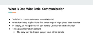
  • 1. What is One Wire Serial Communication ● Serial data transmission over one wire(duh) ● Great for cheap applications that don't require high speed data transfer ● In theory, all AVR processors can handle One Wire Communication ● Timing is extremely important ○ The only way to discern signals from other signals
  • 2. How Does it Work? ● Two basic implementations ○ Polled Implementations(software only) ○ Interrupt driven (counter required) ● Dallas 1-Wire Protocol ○ Designed by the Dallas Semiconductor Corporation ○ Can use either interrupt driven or polled implementations ○ Polled requires no external hardware ○ Half Duplex(transmitting or receiving not Both simultaneously)
  • 3. Dallas 1-Wire ● Signal is idle High, need pull up resistor ● Signaling is divided into time slots of 60µs ● Master initiates every communication ○ Regardless of direction ● 5 basic signals: (Write 1, Write 0, Read, Reset, Presence) ● LSB sent first
  • 4. Overall Communication process All 1-Wire devices follow this basic sequence: 1. The Master sends the Reset pulse. 2. The Slave(s) respond with a Presence pulse. 3. Master sends a ROM command 4. Master sends a Memory command
  • 5. How To Send Bits ● In order to send bits in OW protocol it requires precise timing and precise waveforms ● Errors in these waveforms, or the timing can deliver corrupt data and requires digital error checking
  • 6. Bus Signals ● Write 1 ○ The Master pulls the bus low for 15µs then releases for remainder of 60µs window
  • 7. Bus Signals Continued ● Write 0 ○ The master pulls the bus low for 60µs ● Read ○ Master pulls bus low for 1 to 15µs ○ The slave then releases the line if it wants to write 1 or keeps the line low for write 0 for remainder of 60 us window.
  • 8. Timing Diagram of OW Signals
  • 9. Reset/Presence Signal ● Reset Signal ○ The master pulls the line low for 480µs and then releases it ○ If slave is present then the presence signal should be seen ○ If no presence signal is detected there is no device connected ● Presence Signal ○ After the Reset Signal has been sent it is the slave that must pull the line low for 60µs ○ Must pull the line low within 60µs
  • 11. Generating Signals through Software ● Define delay values ● Define our BUS pin ● Initialize the bus as an output
  • 13. One Wire Write function
  • 14. C++ One Wire Write function
  • 15. One Wire Read Function
  • 16. C++ One Wire Read Bit Function
  • 18. C++ One Wire Reset/Presence Signal
  • 19. Generating the Signals ● Software Only ○ Simply changing the direction and value of a GPIO and generating required delay is sufficient ● With UART ○ Requires both TXD and RXD pins to be connected to the bus ○ Need tri-state or open-collector buffer so the slave can pull the line low.
  • 20. IC for UART Signals DM74LS126A Tri-state Buffer IC
  • 21. Generating UART Signals ● Baud rate is equivalent to bits/sec ● In order to transmit 1-wire framed data from UART platform we must frame the data into the same time slots as in the polled implementation ● One UART data frame is used to generate one waveform bit of 1 wire data or one RESET/Presence signal
  • 22. Framing 1-Wire from UART ● To match waveform UART data frame must match 1-Wire data frame ● All UART signals initiate with a start bit “0” or LOW ● To “Write 1” in one wire format all bits in UART Frame after Start bit must be HIGH or “1” ● To “Write 0” all bits in UART data frame are “0” or LOW ● Stop bit is always HIGH or “1”
  • 23. ● “Read 1” Start bit is LOW and slave writes bit “1” or HIGH in the remaining data bits in UART frame ● “Read 0” start bit is LOW and the slave drives the bus low by writing “0” to the rest of the UART bit pattern and drives the bus HIGH for the STOP bit. Generating One Wire Frame From UART
  • 24. Reset/Presence Signal with UART ● UART bits 0-3 are LOW, 4 is HIGH, and Slave writes UART bits 5,6,&7 LOW ● Stop bit for this signal is HIGH
  • 25. Overall Communication process All 1-Wire devices follow this basic sequence(MUST FOLLOW): 1. The Master sends the Reset pulse. 2. The Slave(s) respond with a Presence pulse. 3. Master sends a ROM command 4. Master sends a Memory command
  • 26. ROM Commands ● All 1-Wire devices contain a 64 bit identifier stored in ROM ● ROM Commands address those 64 bit identifiers ● After bus master detects a presence pulse it can issue a ROM command to detect how many slaves are on the bus, and which slave to address.
  • 27. ROM Commands MAX31820 ● Read ROM(33h)-Reads the ROM code of single slave device. If there are multiple slave devices and the command is issued, data collision will occur. ● Skip ROM(CCh)-Sends data for addressing to all connected slave devices ● Match ROM(55h)-Is used to address individual slave devices on the bus ● Search ROM(F0h)-Is used to get the ID of slave devices if not known
  • 28. Cyclic Redundancy Check ● CRC is used an every ROM command to check for data integrity. ● CRC - is an error detection code for digital networks. ● It sends a check value along with the data that is transmitted. This value is determined by dividing the data by a nominal value and returning the remainder. ● If once the data is received and the remainder value is not the same, after the received data has been divided by the nominal value, then we know the data has been corrupted.
  • 29. How CRC works ● We can think of CRC as an 8 bit shift register with feedback
  • 30. How CRC Works ● At the beginning of a 64 bit Read ROM command the CRC shift register has an initial value of zero. CRC = 0x00 ● The LSB of the 64 bit identifier is XORd with the LSB of the input data. In the case of 64 bit identifiers the LSB is a family CRC code(ex: 0xA2). So after the first byte of data has been processed the CRC register will contain the value of the CRC code. CRC = 0xA2 ● After the entire 64 bit identifier has been shifted into and out of the CRC register the register should have a final value of 0x00 if no data was corrupted. If data was corrupted we would have a value inside the CRC shift register and the data would have to be retransmitted.
  • 31. CRC Computation of 1-Wire(Look up Table) 1. Dallas Semiconductor Corp. provides a table for CRC calculations. This table rapidly increase CRC calculations and can process entire bytes of data per loop run. 2. CRC register is initially zero we then shift in the first byte of 64 bit ID into register 3. Then we XOR the next byte of data with the CRC register 4. Using pgm_read_byte we point to the index of our table and set our CRC register to that new value. We are indexing by the XORd value of the CRC register and the input data. 5. We repeat steps 4 and 5 until we are done with all 64 bits or 8 bytes of our ID. 6. If CRC is 0 then no data was corrupted else data has been corrupted.
  • 32. CRC Function Code Example
  • 33. CRC Look Up Method This table shows how each byte of data gets shifted into our CRC register and how we calculate the next index for our CRC value.
  • 34. Overall Communication process All 1-Wire devices follow this basic sequence(MUST FOLLOW): 1. The Master sends the Reset pulse. 2. The Slave(s) respond with a Presence pulse. 3. Master sends a ROM command 4. Master sends a Memory command
  • 35. Memory Commands ● Are commands specific to slave devices or a class of devices ● They deal with the internal memory and registers of slave devices ● Therefore for each device memory commands are specific to that device
  • 36. MAX31820 Memory Registers ● Memory commands specific to this device would address this device's internal memory registers ● TH and TL would address BYTE 2 and BYTE 3 of the temperature sensors internal scratchpad memory MAX31820 - Ambient Temperature Sensor
  • 37. MAX31820 Configuration Registers ● Bits R1 and R0 control the resolution of the temperature reading ● Better resolution slower conversion time, and faster conversion time less resolution
  • 39. Overall Communication process All 1-Wire devices follow this basic sequence: 1. The Master sends the Reset pulse. 2. The Slave(s) respond with a Presence pulse. 3. Master sends a ROM command 4. Master sends a Memory command
  • 40. 1 Wire Digital Temperature Sensor Implementation ● Assemble this simple circuit, the resistor is needed for the idle state of the bus(HIGH) ● Also because it will act as a pull up resistor Step 1
  • 41. Download Necessary Libraries Step 2 ● Download OneWire Arduino Library ● Download DallasTemperature Arduino Library ● Place both libraries into your Arduino library path ● Include both libraries in your C++ code 1 Wire Digital Temperature Sensor Implementation
  • 42. 1 Wire Digital Temperature Sensor Implementation Step 3 Arduino Code
  • 43. OneWire and DallasTemperature functions ● OneWire oneWire(ONE_WIRE_BUS) - this is a data structure defined in the one wire library ● DallasTemperature sensors(&oneWire) - this is another data structure defined in the DallasTemperature library that is an array of 8 bytes.(that is why the structure must be passed as a pointer)
  • 44. OneWire and DallasTemperature functions ● sensors.begin - is a subroutine in the DallasTemperature library that identifies the type of temperature sensor on the bus and initializes the type of power supply the temperature sensors requires. ● sensors.requestTemperatures - sends a reset/presence signal to begin communication with device. Once presence is detected skip ROM command is sent because only one temperature sensor is on the bus. Then we issue a memory command that begins to send data of the temperature back to the master device.
  • 45. ● sensors.getTempCByIndex(0) - This function returns the temperature in celsius detected by the temperature sensor. If device is disconnected during process it will return “DEVICE_DISCONNECTED_C”. OneWire and DallasTemperature functions
  • 47. Questions 1. How long are the time divisions of each bit level command? 2. What is the Idle state of the bus line? 3. What are the types of implementations of one wire? 4. Which implementation requires external hardware? 5. How does the master know there is a slave device connected? 6. Where are the 64 bit IDs of connected devices stored? 7. Which signal takes more than 1 time slot to transmit? 8. What device is needed for one wire UART? 9. What is the waveform of the write 1 signal? 10. Can data be both transmitted and received simultaneously by the one wire protocol?
  • 48. Answers 1. 60 microseconds 2. HIGH 3. Polled, UART(interrupt driven) 4. UART 5. Presence signal 6. ROM 7. Reset/Presence Signal 8. Tri-state buffer 9. Draw 10. No