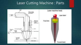
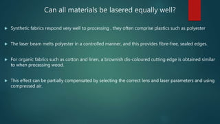
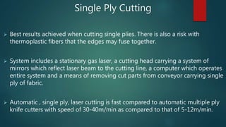
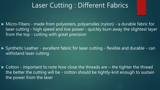
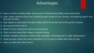
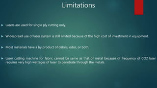
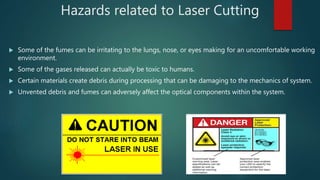
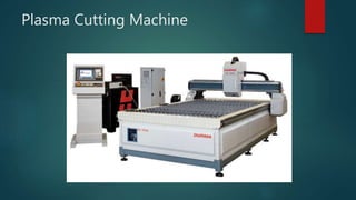
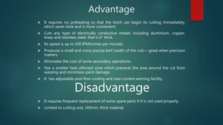
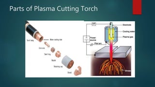
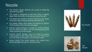
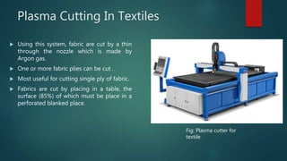
Sewn Products, Machinery & Equipments-II
Laser Cutting & Plasma Cutting
By :- Bittu Singh &
Shubham Singh;
Semester IV, B.F.Tech;
NIFT Gandhinagar
Laser Cutting Machine : Introduction
 Laser - optical device that emits coherent light (electromagnetic
radiation)
 LASER - acronym for Light Amplification by Stimulated Emission of
Radiation
 Lasers - emit light in a narrow, low-divergence beam, with a narrow
wavelength spectrum (monochromatic light)
 Cutting fabric with a laser - produces “sealed” seams without fraying
 Spatial coherence - allows laser to be focused to a very small
spot(0.25mm) - this enables applications like laser cutting
 Cutting - takes place by burning, melting and vaporisation
 Fabrics – can be laser engraved to produce unique effects
 Power output of laser - can be controlled depending upon the intended
end use
Laser Development Process
Carried out in 4 steps :
1.) Pumping- In Laser, lasing medium is “pumped” to get
atoms to an excited state(higher energy levels).
2.) Stimulated Emission of atoms- This creates a large
collection of excited state atoms, thus degree of
population inversion increases.
3.) Reflection- The lasing process is enriched by multiple
reflection between mirrors.
4.) Production of Laser Beam- Laser beam exists, the emitted
energy comes in the form of photons which has very
specific wavelength(depends upon the state of electron
energy).
Types of Laser Cutting
 3 types of laser cutting machines :
1. CO2 lasers
2. Nd (Neodymium)
3. Nd-YAG (Neodymium-doped Yttrium Aluminum Garnet; Nd:Y3Al5O12)
 The CO2 (wavelength -10600 nm) laser cutting machines - used in garment industry -
easily absorbed by organic materials
 Nd and Nd-YAG lasers – solid state lasers that rely on a crystal to create the light
beam – high powered methods – well suited for engraving, welding, cutting and
drilling metals
 3 different configurations of industrial laser cutting machines -
moving material, hybrid, flying optic system
 Refer to the way that the laser beam is moved over the material to be cut - Axes of
motion are typically designated “x” and “y” axis - If cutting head may be controlled, it
is designated as “z” axis
Laser Cutting Machines : Working
 Design made on the computer - it is read by a computer that uses the
information to automatically guide a laser - makes all the necessary
cuts, producing an exact physical replica of the design
 Laser optics and CNC (Computer Numerical Control) - used to direct the
material or the laser beam generated - motion control system follows
a G-code of the pattern to be cut onto the material
 Laser energy - generated by passing a current through a chamber of
CO2 - it continues to reflect until it achieves sufficient energy to escape
as a stream of monochromatic coherent light
 Series of mirrors - direct the coherent light to a lens - focuses light to a
powerful beam
 System - includes a stationary gas laser, a cutting head carrying mirrors
which reflect laser beam to the cutting line, a computer which operates
the entire system, and a means of removing cut parts from the
conveyor carrying the single ply of fabric
Quality & Tolerance
 Fiber cutting lasers - permit controlled heat entry which is optimum for fine
cutting
 Peak performance of laser - maximum cut depth up to 10mm
 Laser beam can be focused on a very small diameter for high precision -
minimum cut width of up to 15 µm (0.0006 in)
 Smallest possible cut width - dependent on beam characteristics and material
strength
 Cutting fine contours - precision and dynamics of the cutting machine are
important
Quality & Tolerance
• Heat-affected zone along the cut - very small (upto 2µm)
• Deformations of the parts to be processed can be avoided
• High energy depth in the focus point of the laser beam - causes
material to melt and evaporate
• Active or neutral process gas - Oxygen, nitrogen, or argon –
melted material is blown out
Laser Cutting Machine : Parts
Laser cutting machine head
 Laser machine head
 Laser cutting head
 Mirror mounts
 Focal lens and reflecting mirror
 CO2 laser tube
 Nozzle
 Gas inlet
 Pressure gauge
 Laser beam
 Attached Water coolant
 Software requirement- The default Control Software is
used.
 AutoCAD or Corel Draw can also be used.
Laser Cutting Machine : Parts
Laser Cutting : Textile Materials
 Cotton Felt Silk Linen Lace Polyester
 Fleece Soft shell Denim Alcantara Neoprene
Laser : Applications in the Garment Industry
1. Cloth Cut & Hollow
2. Cutting Engraving & Hole Drilling
3. Engrave & Punch
4. Jeans Engraving
5. Fur Coat Engraving
Can all materials be lasered equally well?
 Synthetic fabrics respond very well to processing , they often comprise plastics such as polyester
 The laser beam melts polyester in a controlled manner, and this provides fibre-free, sealed edges.
 For organic fabrics such as cotton and linen, a brownish dis-coloured cutting edge is obtained similar
to when processing wood.
 This effect can be partially compensated by selecting the correct lens and laser parameters and using
compressed air.
 Best results achieved when cutting single plies. There is also a risk with
thermoplastic fibers that the edges may fuse together.
 System includes a stationary gas laser, a cutting head carrying a system of
mirrors which reflect laser beam to the cutting line, a computer which operates
entire system and a means of removing cut parts from conveyor carrying single
ply of fabric.
 Automatic , single ply, laser cutting is fast compared to automatic multiple ply
knife cutters with speed of 30-40m/min as compared to that of 5-12m/min.
Single Ply Cutting
Laser Cutting Machine : Configurations
Generally, there are 3 different configurations of industrial laser cutting machines :
1. Moving material
2. Hybrid
3. Flying optic system.
These refer to the way that the laser beam is moved over the material to be cut.
 The axes of motion are typically designated “x” and “y” axis. If the cutting head
may be controlled it is designated as the “z” axis.
 Speed of Laser cutting machine- 30-40m/min
 Gas used in Laser Cutting machine- CO2 (wavelength- 10600nm)
Laser Cutting : Different Fabrics
 Micro-Fibers - made from polyesters, polyamides (nylon) - a durable fabric for
laser cutting - high speed and low power - quickly burn away the slightest layer
from the top - cutting with great precision
 Synthetic Leather - excellent fabric for laser cutting - flexible and durable - can
withstand laser cutting.
 Cotton - important to note how close the threads are – the tighter the thread
the better the cutting will be - cotton should be tightly-knit enough to sustain
the power from the laser
Advantages
 Lasers cut with incredible speed. Accuracy and multidirectional ability is also appreciated.
 Laser cutters operate without any mechanical parts except for the conveyor and plotting system, thus
less wear and tear.
 High degree of automation has been widely used in the leather and textile garment industry.
 No warping of the material
 Doesn't thrusts mechanical stress to the work piece
 Clean cuts and sealed fabric edges to prevent fraying
 Enables complete utilization of fabric width, regardless of discrepancies in width measurement.
 Single ply laser cutters also make it possible to cut by color or shade rather than by style.
 Laser can work with stretch fabrics.
Limitations
 Lasers are used for single ply cutting only.
 Widespread use of laser system is still limited because of the high cost of investment in equipment.
 Most materials have a by product of debris, odor, or both.
 Laser cutting machine for fabric cannot be same as that of metal because of frequency of CO2 laser
requires very high wattages of laser to penetrate through the metals.
Hazards related to Laser Cutting
 Some of the fumes can be irritating to the lungs, nose, or eyes making for an uncomfortable working
environment.
 Some of the gases released can actually be toxic to humans.
 Certain materials create debris during processing that can be damaging to the mechanics of system.
 Unvented debris and fumes can adversely affect the optical components within the system.
Latest Developments
 Gerber Technology – developed work-piece supporting bed for
Laser cutter to minimize snagging in fabric
 New type of supporting bed :–
• Series of thin bands arranged parallel in a plane to form an even
support surface
• Bands are tensioned between two braces
• One brace is fixed
• Other brace is secured via a tensioning screw to an opposite end
frame – tension can be adjusted
• Bands engage a work-sheet and transport it to or from the bed
• Upper edges of the band are smooth – fabric sheets slide along
easily without snagging
Factors that should be considered before buying Laser
cutting machine
 Laser power
 Laser type
 Cutting speed
 Movement of laser (x,y,z)
 Maximum width that can be cut.
 Laser cutting depth
 Materials that can be cut.
 Cooling mode
 Working area/ Processing area
 Working voltage
 Life hours of laser tube.
 Power supply
 Slope Engraving
 Resetting Positioning Accuracy
 Graphic format supported and controlling software, etc.
General Specifications
Parameter Description
Working Area 2000mm X 3000mm
Laser Source CO2
Working Table Conveyor Working Table
Speed 1-1414 mm/sec
Positioning Accuracy ±0.1 mm
Material Clearance 60-80 mm
Laser Power 60 to 600 Watts
Acceleration 9 m/s²
Motion System Servo motor motion system; 5” LCD screen; CNC system
Cooling System Constant temperature water chiller
Power Supply AC 220V; 60 Hz
Format Supported AI, BMP, PLT, DXF, DST etc.
Plasma Cutting
Plasma
 Plasma can be defined as a partially or wholly ionized gas with a roughly
equal number of positively and negatively charged particles.
 Plasma is considered as the “fourth state of matter” because while plasma
is neither gas nor liquid, its properties are similar to those of both gases
and liquids
 Plasma can flow like a liquid or it can contain areas that are like clumps of
atoms sticking together.
 Usually helium, argon, oxygen, nitrogen, air and mixtures of
nitrogen/hydrogen and argon/hydrogen are used.
Plasma Cutting Machine
Plasma Cutting
 Process used to cut steel and other metals using a plasma torch.
 In this process, an inert gas (in some cases, compressed air) is blown at
high speed out of a nozzle.
 At the same time an electrical arc is formed through that gas from the
nozzle to the surface being cut, turning some of that gas to plasma.
 Computer-controlled torches can pierce and cut steel up to 150mm thick.
 The plasma is sufficiently hot to melt the metal being cut and moves
sufficiently fast to blow molten metal away from the cut.
 It is an effective means of cutting thin and thick materials alike.
 Plasma cutting is used to cut
 ferrous (stainless steel, cast iron, pig steel, etc.)
 non-ferrous metal (aluminum, copper, tool steel, die steel, lead,
nickel, tin, titanium and zinc, and alloys such as brass, etc).
 The plasma arc cutting (PAC) torches are available in various
current ranges:
(a) Low power (operating at 30A or less)
(b) Medium power level (30-100A), and
(c) High power (100-1000A).
Working
 Plasma cutters work by sending a
pressurized gas (nitrogen, argon, or
oxygen) through a small channel.
 In the middle of this channel, a
negatively charged electrode exists.
 When applying power to the negative
electrode, and connecting the tip of the
nozzle to the metal, the bond creates a
circuit.
 This will generate a powerful spark,
created through the electrode and
metal bond.
 As the gas passes through the channel,
the spark boosts the temperature of the
gas until it reaches the fourth state of
matter called plasma.
Advantage
 It requires no preheating so that the torch can begin its cutting immediately,
which saves time and is more convenient.
 Cuts any type of electrically conductive metals including aluminium, copper,
brass and stainless steel, that is 6” thick.
 Its speed is up to 500 IPM(inches per minute).
 Produces a small and more precise kerf (width of the cut)— great when precision
matters.
 Eliminates the cost of some secondary operations.
 Has a smaller heat affected zone which prevents the area around the cut from
warping and minimizes paint damage.
 It has adjustable post flow cooling and over current warning facility.
Disadvantage
 It requires frequent replacement of some spare parts if it is not used properly.
 Limited to cutting only 160mm. thick material.
Parts of Plasma Cutting Torch
Nozzle
 The nozzle's design features are crucial to obtaining
optimal cut quality.
 The nozzle is designed so that the orifice is slightly
larger than the vortex of ionized gas being focused.
 This allows the nozzle to contain and focus the vortex
of plasma without being adversely affected by it.
 Cut quality suffers when either the exterior or interior
of the nozzle orifice becomes damaged.
 Internal nozzle damage is caused by current settings
that are either too high or too low (overpowering and
under powering of the nozzle).
 External nozzle damage may be caused by excess
metal spatter on the nozzle that may occur if the torch
cuts too close to the plate or pierces thick metal.
 Nozzle Shield: The shield protects the nozzle from
being damaged during the cutting process.
Fig: Nozzle
Fig:
Nozzle
Cut Quality
Factors to consider in evaluating the quality of a cut include:
 surface smoothness
 kerf width
 dross adherence and sharpness of the top edge
 the type of material being cut
 the equipment being used and
 the cutting conditions.
The process variants, have principally been designed to improve cut
quality and arc stability, reduce the noise and fume or to increase
cutting speed are:
(a) Dual Gas (b) Water Injection (c) Water Shroud
Dual Gas
 A secondary gas shield is introduced
around the nozzle.
 The beneficial effects of the secondary gas
are increased arc constriction and more
effective 'blowing away' of the dross.
 The plasma forming gas is normally argon,
argon-H2 or nitrogen and the secondary
gas is selected according to the metal
being cut.
The advantages compared with conventional
plasma are:
 Reduced risk of 'double arcing‘
 Higher cutting speeds
 Reduction in top edge rounding
Plasma Gas Selection
 Plasma Gas Selection for Plasma Arc Cutting
 Air Plasma
 Nitrogen Plasma
 Argon(65%) / Hydrogen(35%) Plasma
 Oxygen Plasma
 Secondary Gas Selection for Plasma Cutting
 Air Secondary
 CO2 Secondary
 Nitrogen Secondary
Water Injection
 Nitrogen is normally used as the
plasma gas.
 Water is injected radially into the
plasma arc to induce a greater degree
of constriction.
 The temperature is also considerably
increased, to as high as 30,000°C.
 The advantages compared with
conventional plasma are:
 Improvement in cut quality and
squareness of cut
 Increased cutting speeds
 Less risk of 'double arcing‘
 Reduction in nozzle erosion
Water Shroud
 The plasma can be operated either with a water
shroud or even with the workpiece submerged
some 50 to 75mm below the surface of the water.
 Compared with conventional plasma, the water
acts as a barrier to provide the following
advantages:
 Fume reduction
 Reduction in noise levels
 Improved nozzle life
 As the water shroud does not increase the degree
of constriction, squareness of the cut edge and the
cutting speed are not noticeably improved.
Plasma Cutting In Textiles
 Using this system, fabric are cut by a thin
through the nozzle which is made by
Argon gas.
 One or more fabric plies can be cut .
 Most useful for cutting single ply of fabric.
 Fabrics are cut by placing in a table, the
surface (85%) of which must be place in a
perforated blanked place.
Fig: Plasma cutter for
textile
Advantage
 Automatic torch height control system
 Automatic oxy-fuel gas control system
 Automatic torch explosion system
 Pneumatic band clamping
 Standard auto-nesting package
 Easily networked
Disadvantage
 Synthetic fiber not cut
 Higher number of fabric lay is not cut
 Need higher skill operator
 Costly
Technical Specification
JCUT MODEL JCUT-1325A
 X,Y working area: 1500×3000mm
 Lathe bed: Steel structure with water sink
 Industrial fabric cutting table: steel plate
 Working surroundings: temperature range of 0℃--60℃, humidity range of 0-85%
 Processing accuracy: 0.01mm
 Repositioning accuracy: 0.1mm
 Spindle: power 100A(optional:60A/160A/200A)
 Max Moving Speed: 17m/min
 Cutting speed: 0-8m/min
 Travelling speed: 0-50m/min
 Guideway: linear guideway
 Voltage: 380V/50HZ, 65A / 100A / 130A /200A for different thickness cutting
 Feeding Height: 150mm
 Drive motor: Stepper
 Driving mode: Wheel gear
 Command: G code
 Compatible Software: ARTCUT, Type3, ArtCAM. Beihang Haier
 Pack dimensions: 3.1x2.2x1.6m wooden trunk
 Net weight: 900 kg
References
 Nayak, R. & Padhye, R. The use of Laser in Garment Manufacturing : An Overview. Fashion & Textiles
(December 2016). Retrieved from : Link.springer.com
 Rahman K.M. Fabric Laser Cutting Machine. 9 November, 2013. Retrieved from : Autogarment.com
 Garment Fabric Laser Cutting Machine. Retrieved from : Goldenlaser.cc
 Laser systems for Textiles. Retrieved from : Eurolaser.com
 Laser cutting & Engraving textiles. Retrieved from : Troteclaser.com
 Laser cutting machine for garment. Retrieved from : Hsglaser.com
 Laser Machines. Retrieved from : Richpeace.com
 Garment & Textile cutting machines. Retrieved from : Goldenlaserindia.com
 Horton N. & Bell J.K. Computer controlled Laser cutter. 25 March, 1997. Retrieved from : Google Patents
 Pearl D.R. Work-piece supporting bed for Laser cutter. Gerber Garment Technology Inc. 9 June, 1987.
Retrieved from : Google Patents
 Tyler D. J. Carr & Latham’s Technology of Clothing Manufacture. Laser Cutting & Plasma Cutting. Pg. Nos. 44-
45. Fourth Edition. Blackwell Publishing.
References
 Plasma Equipments. Retrieved from : Arcraftplasma.com
 What happens inside a Plasma cutter ? Retrieved from : Multicam.ca
 Plasma arc cutting. Retrieved from : Twi-global.com
 CNC Plasma cutting machines. Retrieved from : Hornetcs.com
 Plasma cutting table. Retrieved from : Murgesi.com
 Using a Plasma cutter. Retrieved from : TheFabricator.com
 Plasma treatment of textile fibers. Retrieved from : Fibre2Fashion.com
Laser cutting & Plasma cutting machines for textiles

Laser cutting & Plasma cutting machines for textiles

  • 1.
    Sewn Products, Machinery& Equipments-II Laser Cutting & Plasma Cutting By :- Bittu Singh & Shubham Singh; Semester IV, B.F.Tech; NIFT Gandhinagar
  • 2.
    Laser Cutting Machine: Introduction  Laser - optical device that emits coherent light (electromagnetic radiation)  LASER - acronym for Light Amplification by Stimulated Emission of Radiation  Lasers - emit light in a narrow, low-divergence beam, with a narrow wavelength spectrum (monochromatic light)  Cutting fabric with a laser - produces “sealed” seams without fraying  Spatial coherence - allows laser to be focused to a very small spot(0.25mm) - this enables applications like laser cutting  Cutting - takes place by burning, melting and vaporisation  Fabrics – can be laser engraved to produce unique effects  Power output of laser - can be controlled depending upon the intended end use
  • 3.
    Laser Development Process Carriedout in 4 steps : 1.) Pumping- In Laser, lasing medium is “pumped” to get atoms to an excited state(higher energy levels). 2.) Stimulated Emission of atoms- This creates a large collection of excited state atoms, thus degree of population inversion increases. 3.) Reflection- The lasing process is enriched by multiple reflection between mirrors. 4.) Production of Laser Beam- Laser beam exists, the emitted energy comes in the form of photons which has very specific wavelength(depends upon the state of electron energy).
  • 4.
    Types of LaserCutting  3 types of laser cutting machines : 1. CO2 lasers 2. Nd (Neodymium) 3. Nd-YAG (Neodymium-doped Yttrium Aluminum Garnet; Nd:Y3Al5O12)  The CO2 (wavelength -10600 nm) laser cutting machines - used in garment industry - easily absorbed by organic materials  Nd and Nd-YAG lasers – solid state lasers that rely on a crystal to create the light beam – high powered methods – well suited for engraving, welding, cutting and drilling metals  3 different configurations of industrial laser cutting machines - moving material, hybrid, flying optic system  Refer to the way that the laser beam is moved over the material to be cut - Axes of motion are typically designated “x” and “y” axis - If cutting head may be controlled, it is designated as “z” axis
  • 5.
    Laser Cutting Machines: Working  Design made on the computer - it is read by a computer that uses the information to automatically guide a laser - makes all the necessary cuts, producing an exact physical replica of the design  Laser optics and CNC (Computer Numerical Control) - used to direct the material or the laser beam generated - motion control system follows a G-code of the pattern to be cut onto the material  Laser energy - generated by passing a current through a chamber of CO2 - it continues to reflect until it achieves sufficient energy to escape as a stream of monochromatic coherent light  Series of mirrors - direct the coherent light to a lens - focuses light to a powerful beam  System - includes a stationary gas laser, a cutting head carrying mirrors which reflect laser beam to the cutting line, a computer which operates the entire system, and a means of removing cut parts from the conveyor carrying the single ply of fabric
  • 6.
    Quality & Tolerance Fiber cutting lasers - permit controlled heat entry which is optimum for fine cutting  Peak performance of laser - maximum cut depth up to 10mm  Laser beam can be focused on a very small diameter for high precision - minimum cut width of up to 15 µm (0.0006 in)  Smallest possible cut width - dependent on beam characteristics and material strength  Cutting fine contours - precision and dynamics of the cutting machine are important
  • 7.
    Quality & Tolerance •Heat-affected zone along the cut - very small (upto 2µm) • Deformations of the parts to be processed can be avoided • High energy depth in the focus point of the laser beam - causes material to melt and evaporate • Active or neutral process gas - Oxygen, nitrogen, or argon – melted material is blown out
  • 8.
    Laser Cutting Machine: Parts Laser cutting machine head  Laser machine head  Laser cutting head  Mirror mounts  Focal lens and reflecting mirror  CO2 laser tube  Nozzle  Gas inlet  Pressure gauge  Laser beam  Attached Water coolant  Software requirement- The default Control Software is used.  AutoCAD or Corel Draw can also be used.
  • 9.
  • 10.
    Laser Cutting :Textile Materials  Cotton Felt Silk Linen Lace Polyester  Fleece Soft shell Denim Alcantara Neoprene Laser : Applications in the Garment Industry 1. Cloth Cut & Hollow 2. Cutting Engraving & Hole Drilling 3. Engrave & Punch 4. Jeans Engraving 5. Fur Coat Engraving
  • 11.
    Can all materialsbe lasered equally well?  Synthetic fabrics respond very well to processing , they often comprise plastics such as polyester  The laser beam melts polyester in a controlled manner, and this provides fibre-free, sealed edges.  For organic fabrics such as cotton and linen, a brownish dis-coloured cutting edge is obtained similar to when processing wood.  This effect can be partially compensated by selecting the correct lens and laser parameters and using compressed air.
  • 12.
     Best resultsachieved when cutting single plies. There is also a risk with thermoplastic fibers that the edges may fuse together.  System includes a stationary gas laser, a cutting head carrying a system of mirrors which reflect laser beam to the cutting line, a computer which operates entire system and a means of removing cut parts from conveyor carrying single ply of fabric.  Automatic , single ply, laser cutting is fast compared to automatic multiple ply knife cutters with speed of 30-40m/min as compared to that of 5-12m/min. Single Ply Cutting
  • 13.
    Laser Cutting Machine: Configurations Generally, there are 3 different configurations of industrial laser cutting machines : 1. Moving material 2. Hybrid 3. Flying optic system. These refer to the way that the laser beam is moved over the material to be cut.  The axes of motion are typically designated “x” and “y” axis. If the cutting head may be controlled it is designated as the “z” axis.  Speed of Laser cutting machine- 30-40m/min  Gas used in Laser Cutting machine- CO2 (wavelength- 10600nm)
  • 14.
    Laser Cutting :Different Fabrics  Micro-Fibers - made from polyesters, polyamides (nylon) - a durable fabric for laser cutting - high speed and low power - quickly burn away the slightest layer from the top - cutting with great precision  Synthetic Leather - excellent fabric for laser cutting - flexible and durable - can withstand laser cutting.  Cotton - important to note how close the threads are – the tighter the thread the better the cutting will be - cotton should be tightly-knit enough to sustain the power from the laser
  • 15.
    Advantages  Lasers cutwith incredible speed. Accuracy and multidirectional ability is also appreciated.  Laser cutters operate without any mechanical parts except for the conveyor and plotting system, thus less wear and tear.  High degree of automation has been widely used in the leather and textile garment industry.  No warping of the material  Doesn't thrusts mechanical stress to the work piece  Clean cuts and sealed fabric edges to prevent fraying  Enables complete utilization of fabric width, regardless of discrepancies in width measurement.  Single ply laser cutters also make it possible to cut by color or shade rather than by style.  Laser can work with stretch fabrics.
  • 16.
    Limitations  Lasers areused for single ply cutting only.  Widespread use of laser system is still limited because of the high cost of investment in equipment.  Most materials have a by product of debris, odor, or both.  Laser cutting machine for fabric cannot be same as that of metal because of frequency of CO2 laser requires very high wattages of laser to penetrate through the metals.
  • 17.
    Hazards related toLaser Cutting  Some of the fumes can be irritating to the lungs, nose, or eyes making for an uncomfortable working environment.  Some of the gases released can actually be toxic to humans.  Certain materials create debris during processing that can be damaging to the mechanics of system.  Unvented debris and fumes can adversely affect the optical components within the system.
  • 18.
    Latest Developments  GerberTechnology – developed work-piece supporting bed for Laser cutter to minimize snagging in fabric  New type of supporting bed :– • Series of thin bands arranged parallel in a plane to form an even support surface • Bands are tensioned between two braces • One brace is fixed • Other brace is secured via a tensioning screw to an opposite end frame – tension can be adjusted • Bands engage a work-sheet and transport it to or from the bed • Upper edges of the band are smooth – fabric sheets slide along easily without snagging
  • 19.
    Factors that shouldbe considered before buying Laser cutting machine  Laser power  Laser type  Cutting speed  Movement of laser (x,y,z)  Maximum width that can be cut.  Laser cutting depth  Materials that can be cut.  Cooling mode  Working area/ Processing area  Working voltage  Life hours of laser tube.  Power supply  Slope Engraving  Resetting Positioning Accuracy  Graphic format supported and controlling software, etc.
  • 20.
    General Specifications Parameter Description WorkingArea 2000mm X 3000mm Laser Source CO2 Working Table Conveyor Working Table Speed 1-1414 mm/sec Positioning Accuracy ±0.1 mm Material Clearance 60-80 mm Laser Power 60 to 600 Watts Acceleration 9 m/s² Motion System Servo motor motion system; 5” LCD screen; CNC system Cooling System Constant temperature water chiller Power Supply AC 220V; 60 Hz Format Supported AI, BMP, PLT, DXF, DST etc.
  • 21.
  • 22.
    Plasma  Plasma canbe defined as a partially or wholly ionized gas with a roughly equal number of positively and negatively charged particles.  Plasma is considered as the “fourth state of matter” because while plasma is neither gas nor liquid, its properties are similar to those of both gases and liquids  Plasma can flow like a liquid or it can contain areas that are like clumps of atoms sticking together.  Usually helium, argon, oxygen, nitrogen, air and mixtures of nitrogen/hydrogen and argon/hydrogen are used.
  • 23.
  • 24.
    Plasma Cutting  Processused to cut steel and other metals using a plasma torch.  In this process, an inert gas (in some cases, compressed air) is blown at high speed out of a nozzle.  At the same time an electrical arc is formed through that gas from the nozzle to the surface being cut, turning some of that gas to plasma.  Computer-controlled torches can pierce and cut steel up to 150mm thick.
  • 25.
     The plasmais sufficiently hot to melt the metal being cut and moves sufficiently fast to blow molten metal away from the cut.  It is an effective means of cutting thin and thick materials alike.  Plasma cutting is used to cut  ferrous (stainless steel, cast iron, pig steel, etc.)  non-ferrous metal (aluminum, copper, tool steel, die steel, lead, nickel, tin, titanium and zinc, and alloys such as brass, etc).  The plasma arc cutting (PAC) torches are available in various current ranges: (a) Low power (operating at 30A or less) (b) Medium power level (30-100A), and (c) High power (100-1000A).
  • 26.
    Working  Plasma cutterswork by sending a pressurized gas (nitrogen, argon, or oxygen) through a small channel.  In the middle of this channel, a negatively charged electrode exists.  When applying power to the negative electrode, and connecting the tip of the nozzle to the metal, the bond creates a circuit.  This will generate a powerful spark, created through the electrode and metal bond.  As the gas passes through the channel, the spark boosts the temperature of the gas until it reaches the fourth state of matter called plasma.
  • 27.
    Advantage  It requiresno preheating so that the torch can begin its cutting immediately, which saves time and is more convenient.  Cuts any type of electrically conductive metals including aluminium, copper, brass and stainless steel, that is 6” thick.  Its speed is up to 500 IPM(inches per minute).  Produces a small and more precise kerf (width of the cut)— great when precision matters.  Eliminates the cost of some secondary operations.  Has a smaller heat affected zone which prevents the area around the cut from warping and minimizes paint damage.  It has adjustable post flow cooling and over current warning facility. Disadvantage  It requires frequent replacement of some spare parts if it is not used properly.  Limited to cutting only 160mm. thick material.
  • 28.
    Parts of PlasmaCutting Torch
  • 29.
    Nozzle  The nozzle'sdesign features are crucial to obtaining optimal cut quality.  The nozzle is designed so that the orifice is slightly larger than the vortex of ionized gas being focused.  This allows the nozzle to contain and focus the vortex of plasma without being adversely affected by it.  Cut quality suffers when either the exterior or interior of the nozzle orifice becomes damaged.  Internal nozzle damage is caused by current settings that are either too high or too low (overpowering and under powering of the nozzle).  External nozzle damage may be caused by excess metal spatter on the nozzle that may occur if the torch cuts too close to the plate or pierces thick metal.  Nozzle Shield: The shield protects the nozzle from being damaged during the cutting process. Fig: Nozzle Fig: Nozzle
  • 30.
    Cut Quality Factors toconsider in evaluating the quality of a cut include:  surface smoothness  kerf width  dross adherence and sharpness of the top edge  the type of material being cut  the equipment being used and  the cutting conditions. The process variants, have principally been designed to improve cut quality and arc stability, reduce the noise and fume or to increase cutting speed are: (a) Dual Gas (b) Water Injection (c) Water Shroud
  • 31.
    Dual Gas  Asecondary gas shield is introduced around the nozzle.  The beneficial effects of the secondary gas are increased arc constriction and more effective 'blowing away' of the dross.  The plasma forming gas is normally argon, argon-H2 or nitrogen and the secondary gas is selected according to the metal being cut. The advantages compared with conventional plasma are:  Reduced risk of 'double arcing‘  Higher cutting speeds  Reduction in top edge rounding
  • 32.
    Plasma Gas Selection Plasma Gas Selection for Plasma Arc Cutting  Air Plasma  Nitrogen Plasma  Argon(65%) / Hydrogen(35%) Plasma  Oxygen Plasma  Secondary Gas Selection for Plasma Cutting  Air Secondary  CO2 Secondary  Nitrogen Secondary
  • 33.
    Water Injection  Nitrogenis normally used as the plasma gas.  Water is injected radially into the plasma arc to induce a greater degree of constriction.  The temperature is also considerably increased, to as high as 30,000°C.  The advantages compared with conventional plasma are:  Improvement in cut quality and squareness of cut  Increased cutting speeds  Less risk of 'double arcing‘  Reduction in nozzle erosion
  • 34.
    Water Shroud  Theplasma can be operated either with a water shroud or even with the workpiece submerged some 50 to 75mm below the surface of the water.  Compared with conventional plasma, the water acts as a barrier to provide the following advantages:  Fume reduction  Reduction in noise levels  Improved nozzle life  As the water shroud does not increase the degree of constriction, squareness of the cut edge and the cutting speed are not noticeably improved.
  • 35.
    Plasma Cutting InTextiles  Using this system, fabric are cut by a thin through the nozzle which is made by Argon gas.  One or more fabric plies can be cut .  Most useful for cutting single ply of fabric.  Fabrics are cut by placing in a table, the surface (85%) of which must be place in a perforated blanked place. Fig: Plasma cutter for textile
  • 36.
    Advantage  Automatic torchheight control system  Automatic oxy-fuel gas control system  Automatic torch explosion system  Pneumatic band clamping  Standard auto-nesting package  Easily networked Disadvantage  Synthetic fiber not cut  Higher number of fabric lay is not cut  Need higher skill operator  Costly
  • 37.
    Technical Specification JCUT MODELJCUT-1325A  X,Y working area: 1500×3000mm  Lathe bed: Steel structure with water sink  Industrial fabric cutting table: steel plate  Working surroundings: temperature range of 0℃--60℃, humidity range of 0-85%  Processing accuracy: 0.01mm  Repositioning accuracy: 0.1mm  Spindle: power 100A(optional:60A/160A/200A)  Max Moving Speed: 17m/min  Cutting speed: 0-8m/min  Travelling speed: 0-50m/min  Guideway: linear guideway  Voltage: 380V/50HZ, 65A / 100A / 130A /200A for different thickness cutting  Feeding Height: 150mm  Drive motor: Stepper  Driving mode: Wheel gear  Command: G code  Compatible Software: ARTCUT, Type3, ArtCAM. Beihang Haier  Pack dimensions: 3.1x2.2x1.6m wooden trunk  Net weight: 900 kg
  • 38.
    References  Nayak, R.& Padhye, R. The use of Laser in Garment Manufacturing : An Overview. Fashion & Textiles (December 2016). Retrieved from : Link.springer.com  Rahman K.M. Fabric Laser Cutting Machine. 9 November, 2013. Retrieved from : Autogarment.com  Garment Fabric Laser Cutting Machine. Retrieved from : Goldenlaser.cc  Laser systems for Textiles. Retrieved from : Eurolaser.com  Laser cutting & Engraving textiles. Retrieved from : Troteclaser.com  Laser cutting machine for garment. Retrieved from : Hsglaser.com  Laser Machines. Retrieved from : Richpeace.com  Garment & Textile cutting machines. Retrieved from : Goldenlaserindia.com  Horton N. & Bell J.K. Computer controlled Laser cutter. 25 March, 1997. Retrieved from : Google Patents  Pearl D.R. Work-piece supporting bed for Laser cutter. Gerber Garment Technology Inc. 9 June, 1987. Retrieved from : Google Patents  Tyler D. J. Carr & Latham’s Technology of Clothing Manufacture. Laser Cutting & Plasma Cutting. Pg. Nos. 44- 45. Fourth Edition. Blackwell Publishing.
  • 39.
    References  Plasma Equipments.Retrieved from : Arcraftplasma.com  What happens inside a Plasma cutter ? Retrieved from : Multicam.ca  Plasma arc cutting. Retrieved from : Twi-global.com  CNC Plasma cutting machines. Retrieved from : Hornetcs.com  Plasma cutting table. Retrieved from : Murgesi.com  Using a Plasma cutter. Retrieved from : TheFabricator.com  Plasma treatment of textile fibers. Retrieved from : Fibre2Fashion.com