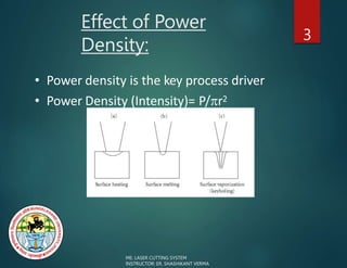
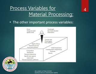
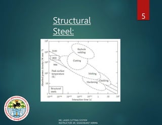
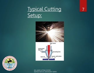
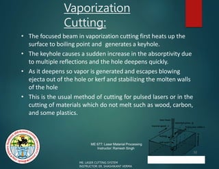
SUBMITTED BY: SUBMITTED TO :
MOHD. KASHIF SIDDIQUI ER. SHASHIKANT VERMA
COURSE: BACHELOR OF TECHNOLOGY SUBMISSION DATE: 24/05/2022
BRANCH: MECHANICAL ENGINEERING
YEAR: 3rd YEAR
BUNDELKHAND UNIVERSITY
, JHANSI​
SEMINAR PRESENTATION ON
LASER CUTTING SYSTEM
Outline: 2
• Materials Processing Parameters
• Process Description
• Mechanisms of Laser Cutting
ME: LASER CUTTING SYSTEM
INSTRUCTOR: ER. SHASHIKANT VERMA
Effect of Power
Density:
3
• Power density is the key process driver
• Power Density (Intensity)= P/r2
ME: LASER CUTTING SYSTEM
INSTRUCTOR: ER. SHASHIKANT VERMA
Process Variables for
Material Processing:
4
• The other important process variables:
ME: LASER CUTTING SYSTEM
INSTRUCTOR: ER. SHASHIKANT VERMA
Structural
Steel:
5
ME: LASER CUTTING SYSTEM
INSTRUCTOR: ER. SHASHIKANT VERMA
Cutting:
6
ME: LASER CUTTING SYSTEM
INSTRUCTOR: ER. SHASHIKANT VERMA
• Laser cutting is able to cut faster and with a higher quality
than competing process:
- punch ,plasma, abrasive water jet, ultrasonic, Oxyflame, sawing
and milling.
• Can be automated.
• 80% industrial layers in Japan are used for metal cutting
Typical Cutting
Setup:
7
ME: LASER CUTTING SYSTEM
INSTRUCTOR: ER. SHASHIKANT VERMA
Process
Characteristics: 8
• It is one of the faster cutting processes.
• The work piece does not need clamping but workholding is advisable to
avoid shifting with the table acceleration and for locating when using a
CNC program
• Tool wear is zero since the process is a non contact cutting process.
• Cuts can be made in any direction polarization may affect process
efficiency
• The noise level is low.
• The process can be easily automated with good prospects for adaptive
control in the future.
• No expensive tooling changes are mainly "soft". That is they are only
programming changes. Thus the process is highly flexible.
• Some materials can be stack cut, but there may be a problem with
welding between layers.
• Nearly all engineering materials can be cut. They can be friable, brittle,
electric conductors or non conductors, hard or soft.
– Only highly reflective materials such as aluminium and copper can pose a
problem but with proper beam control these can be cut satisfactorily.
ME: LASER CUTTING SYSTEM
INSTRUCTOR: ER. SHASHIKANT VERMA
Process
Mechanisms: 9
• The beam is traversed over a programmed path and material
removal occurs due to multiple mechanisms
• Melting
– Material exhibiting molten phase of low viscosity, notably metals and
alloys, and thermoplastics, are cut by the heating action of a beam of
power density on the order of 104 Wmm−2
– The melt is assisted by shearing action of a stream of inert or active
assist gas, results in formation of a molten channel through the
material called a kerf (slot).
• Vaporisation
– Suitable for materials that are not readily melted (some glasses,
ceramics and composites)
– Materials can be cut by vaporization that is induced by a higher beam
power density (>104 Wmm−2)
• Chemical Degradation
– A kerf can be formed in many organic materials by chemical
degradation caused by the heating action of the beam.
ME: LASER CUTTING SYSTEM
INSTRUCTOR: ER. SHASHIKANT VERMA
Process
Response: 10
• The cut can have a very narrow kerf width giving a substantial saving in
material. (Kerf is the width of the cut opening)
• The cut edges can be square and not rounded as with most hot jet
processes or other thermal cutting techniques.
• The cut edge can be smooth and clean. It is a finished cut, requiring no further
cleaning or treatment.
• The cut edge can be directly re-welded with little to no surface
preparation.
• There is no edge burr as with mechanical cutting techniques. Dross
adhesion can usually be avoided.
• There is a very narrow HAZ (Heat Affected Zone) and very thin re-
solidified layer of few m, particularly on dross free cuts. There is
negligible distortion.
• Blind cuts can be made in some materials, particularly those which
volatilise, such as wood or acrylic.
• Cut depth depends on the laser power. 10-20mm is the current range for high
quality cuts. Some very high power fiber lasers could cut 50 mm.
ME: LASER CUTTING SYSTEM
INSTRUCTOR: ER. SHASHIKANT VERMA
Cutting
Action:
11
• The beam is incident on the surface
– Most of the beam passes into the hole
or kerf
– some is reflected off the unmelted
surface
– some may pass straight through.
• At slow speeds the melt starts at the
leading edge of the beam and much
of the beam passes clean through the
kerf without touching if the material
is sufficiently thin
ME: LASER CUTTING SYSTEM
INSTRUCTOR: ER. SHASHIKANT VERMA
Material Removal Mechanism
in Different Materials: 12
ME: LASER CUTTING SYSTEM
INSTRUCTOR: ER. SHASHIKANT VERMA
Inert Gas Melt Shearing or Melt and
Blow
13
Viewed from Top
ME: LASER CUTTING SYSTEM
INSTRUCTOR: ER. SHASHIKANT VERMA
14
• Once a penetration hole is made or the cut is
started from the edge, then
• A sufficiently strong gas jet could blow the
molten material out of the cut kerf to prevent the
temperature rise to the boiling point any further
• Cutting with inert gas jet requires only one tenth
of the power required for vaporization
• Note that the ratio latent heat of melting to
vaporization is 1:20.
MELT AND BLOW:
ME: LASER CUTTING SYSTEM
INSTRUCTOR: ER. SHASHIKANT VERMA
Formation of
Striations:
15
• As the cut rate is increased the beam is automatically coupled to the work piece
more efficiently due to reduced losses through the kerf .
• Also the beam tends to ride ahead onto the unmelted material. When this occurs
the power density increases since the surface is not sloped
• The melt proceeds faster and is swept down into the kerf as a step. As the step is
swept down it leaves behind a mark on the cut edge called a striation.
• The cause of striations is disputed, there are many theories:
– The step theory
– critical droplet size causing the melt to pulsate in size before it can be blown free
– The sideways burning theory.
• There are conditions under which no striations occur. These are governed by gas
flow or by pulsing at the frequency of the natural striation
ME: LASER CUTTING SYSTEM
INSTRUCTOR: ER. SHASHIKANT VERMA
ME: LASER CUTTING SYSTEM
Striations: 16
ME: LASER CUTTING SYSTEM
INSTRUCTOR: ER. SHASHIKANT VERMA
Reactive Fusion:
17
• The amount of energy supplied by the burning reaction
varies with the material
– with mild/stainless steel it is 60%
– with a reactive metal like titanium it is around 90%.
• Cutting speeds could be doubled using this technique.
• Typically, the faster the cut, the less heat penetration and the
better the quality.
• A chemical change in the workpiece may happen due to
reactive fusion.
– With titanium this can be critical since the edge will have
some oxygen in it and will be harder and more liable to
cracking.
– With mild steel there is no noticeable effect except a very thin
re-solidified layer of oxide on the surface of the
ME: LASER CUTTING SYSTEM
INSTRUCTOR: ER. SHASHIKANT VERMA
Striations in Reactive Fusion
Cutting: 18
ME: LASER CUTTING SYSTEM
INSTRUCTOR: ER. SHASHIKANT VERMA
Controlled Fracture
Process: 19
• Brittle material are vulnerable to thermal fracture can be
quickly and neatly severed by guiding a crack with a fine
spot heated by a laser
• The laser heats a small volume of the surface causing it to
expand and hence to cause tensile stresses all around it
• If there is a crack in this space, it will act as a stress raiser
and the cracking will continue in direction of the hot spot
• The speed at which a crack can be guided is of the
order of m/s
• When the crack approaches an edge, the stress fields
become more complex
ME: LASER CUTTING SYSTEM
INSTRUCTOR: ER. SHASHIKANT VERMA
Scribing:
20
• This is a process for making a groove or line of holes either
fully or partially penetrating
• This sufficiently weakens the structure so that it can be
mechanically broken
• Typically materials processed are silicon chips and alumina
substrates
• Quality is measured by the lack of debris and low heat
affected zone
• Thus low energy, high power density pulses are used to
remove the material principally as vapor
ME: LASER CUTTING SYSTEM
INSTRUCTOR: ER. SHASHIKANT VERMA
ME 677: Laser Material Processing
Instructor: Ramesh Singh
Vaporization
Cutting:
• The focused beam in vaporization cutting first heats up the
surface to boiling point and generates a keyhole.
• The keyhole causes a sudden increase in the absorptivity due
to multiple reflections and the hole deepens quickly.
• As it deepens so vapor is generated and escapes blowing
ejecta out of the hole or kerf and stabilizing the molten walls
of the hole
• This is the usual method of cutting for pulsed lasers or in the
cutting of materials which do not melt such as wood, carbon,
and some plastics.
32
ME: LASER CUTTING SYSTEM
INSTRUCTOR: ER. SHASHIKANT VERMA
Spot size
and
Effect of Spot Size:
22
• The principle parameters are laser power, traverse speed,
spot size and material thickness .
• Spot size acts in two ways:
– Firstly, a decrease in spot size will increase the power density which
affects the absorption and
– Secondly, it will decrease the cut width.
ME: LASER CUTTING SYSTEM
INSTRUCTOR: ER. SHASHIKANT VERMA
Wavelength: 23
ME: LASER CUTTING SYSTEM
INSTRUCTOR: ER. SHASHIKANT VERMA
• Shorter the wavelength the higher the absorptivity for most metals .
• Thus YAG radiation is preferred to CO2 radiation but the poor mood
structure of most YAG laser the benefit is offset.
• Fiber laser with good beam mode could have an advantage.
Summary:
24
• Basics of laser cutting
• Mechanisms
• Factors affecting laser cutting
ME: LASER CUTTING SYSTEM
INSTRUCTOR: ER. SHASHIKANT VERMA

lasercutting (1) (1).pptx

  • 1.
    SUBMITTED BY: SUBMITTEDTO : MOHD. KASHIF SIDDIQUI ER. SHASHIKANT VERMA COURSE: BACHELOR OF TECHNOLOGY SUBMISSION DATE: 24/05/2022 BRANCH: MECHANICAL ENGINEERING YEAR: 3rd YEAR BUNDELKHAND UNIVERSITY , JHANSI​ SEMINAR PRESENTATION ON LASER CUTTING SYSTEM
  • 2.
    Outline: 2 • MaterialsProcessing Parameters • Process Description • Mechanisms of Laser Cutting ME: LASER CUTTING SYSTEM INSTRUCTOR: ER. SHASHIKANT VERMA
  • 3.
    Effect of Power Density: 3 •Power density is the key process driver • Power Density (Intensity)= P/r2 ME: LASER CUTTING SYSTEM INSTRUCTOR: ER. SHASHIKANT VERMA
  • 4.
    Process Variables for MaterialProcessing: 4 • The other important process variables: ME: LASER CUTTING SYSTEM INSTRUCTOR: ER. SHASHIKANT VERMA
  • 5.
    Structural Steel: 5 ME: LASER CUTTINGSYSTEM INSTRUCTOR: ER. SHASHIKANT VERMA
  • 6.
    Cutting: 6 ME: LASER CUTTINGSYSTEM INSTRUCTOR: ER. SHASHIKANT VERMA • Laser cutting is able to cut faster and with a higher quality than competing process: - punch ,plasma, abrasive water jet, ultrasonic, Oxyflame, sawing and milling. • Can be automated. • 80% industrial layers in Japan are used for metal cutting
  • 7.
    Typical Cutting Setup: 7 ME: LASERCUTTING SYSTEM INSTRUCTOR: ER. SHASHIKANT VERMA
  • 8.
    Process Characteristics: 8 • Itis one of the faster cutting processes. • The work piece does not need clamping but workholding is advisable to avoid shifting with the table acceleration and for locating when using a CNC program • Tool wear is zero since the process is a non contact cutting process. • Cuts can be made in any direction polarization may affect process efficiency • The noise level is low. • The process can be easily automated with good prospects for adaptive control in the future. • No expensive tooling changes are mainly "soft". That is they are only programming changes. Thus the process is highly flexible. • Some materials can be stack cut, but there may be a problem with welding between layers. • Nearly all engineering materials can be cut. They can be friable, brittle, electric conductors or non conductors, hard or soft. – Only highly reflective materials such as aluminium and copper can pose a problem but with proper beam control these can be cut satisfactorily. ME: LASER CUTTING SYSTEM INSTRUCTOR: ER. SHASHIKANT VERMA
  • 9.
    Process Mechanisms: 9 • Thebeam is traversed over a programmed path and material removal occurs due to multiple mechanisms • Melting – Material exhibiting molten phase of low viscosity, notably metals and alloys, and thermoplastics, are cut by the heating action of a beam of power density on the order of 104 Wmm−2 – The melt is assisted by shearing action of a stream of inert or active assist gas, results in formation of a molten channel through the material called a kerf (slot). • Vaporisation – Suitable for materials that are not readily melted (some glasses, ceramics and composites) – Materials can be cut by vaporization that is induced by a higher beam power density (>104 Wmm−2) • Chemical Degradation – A kerf can be formed in many organic materials by chemical degradation caused by the heating action of the beam. ME: LASER CUTTING SYSTEM INSTRUCTOR: ER. SHASHIKANT VERMA
  • 10.
    Process Response: 10 • Thecut can have a very narrow kerf width giving a substantial saving in material. (Kerf is the width of the cut opening) • The cut edges can be square and not rounded as with most hot jet processes or other thermal cutting techniques. • The cut edge can be smooth and clean. It is a finished cut, requiring no further cleaning or treatment. • The cut edge can be directly re-welded with little to no surface preparation. • There is no edge burr as with mechanical cutting techniques. Dross adhesion can usually be avoided. • There is a very narrow HAZ (Heat Affected Zone) and very thin re- solidified layer of few m, particularly on dross free cuts. There is negligible distortion. • Blind cuts can be made in some materials, particularly those which volatilise, such as wood or acrylic. • Cut depth depends on the laser power. 10-20mm is the current range for high quality cuts. Some very high power fiber lasers could cut 50 mm. ME: LASER CUTTING SYSTEM INSTRUCTOR: ER. SHASHIKANT VERMA
  • 11.
    Cutting Action: 11 • The beamis incident on the surface – Most of the beam passes into the hole or kerf – some is reflected off the unmelted surface – some may pass straight through. • At slow speeds the melt starts at the leading edge of the beam and much of the beam passes clean through the kerf without touching if the material is sufficiently thin ME: LASER CUTTING SYSTEM INSTRUCTOR: ER. SHASHIKANT VERMA
  • 12.
    Material Removal Mechanism inDifferent Materials: 12 ME: LASER CUTTING SYSTEM INSTRUCTOR: ER. SHASHIKANT VERMA
  • 13.
    Inert Gas MeltShearing or Melt and Blow 13 Viewed from Top ME: LASER CUTTING SYSTEM INSTRUCTOR: ER. SHASHIKANT VERMA
  • 14.
    14 • Once apenetration hole is made or the cut is started from the edge, then • A sufficiently strong gas jet could blow the molten material out of the cut kerf to prevent the temperature rise to the boiling point any further • Cutting with inert gas jet requires only one tenth of the power required for vaporization • Note that the ratio latent heat of melting to vaporization is 1:20. MELT AND BLOW: ME: LASER CUTTING SYSTEM INSTRUCTOR: ER. SHASHIKANT VERMA
  • 15.
    Formation of Striations: 15 • Asthe cut rate is increased the beam is automatically coupled to the work piece more efficiently due to reduced losses through the kerf . • Also the beam tends to ride ahead onto the unmelted material. When this occurs the power density increases since the surface is not sloped • The melt proceeds faster and is swept down into the kerf as a step. As the step is swept down it leaves behind a mark on the cut edge called a striation. • The cause of striations is disputed, there are many theories: – The step theory – critical droplet size causing the melt to pulsate in size before it can be blown free – The sideways burning theory. • There are conditions under which no striations occur. These are governed by gas flow or by pulsing at the frequency of the natural striation ME: LASER CUTTING SYSTEM INSTRUCTOR: ER. SHASHIKANT VERMA ME: LASER CUTTING SYSTEM
  • 16.
    Striations: 16 ME: LASERCUTTING SYSTEM INSTRUCTOR: ER. SHASHIKANT VERMA
  • 17.
    Reactive Fusion: 17 • Theamount of energy supplied by the burning reaction varies with the material – with mild/stainless steel it is 60% – with a reactive metal like titanium it is around 90%. • Cutting speeds could be doubled using this technique. • Typically, the faster the cut, the less heat penetration and the better the quality. • A chemical change in the workpiece may happen due to reactive fusion. – With titanium this can be critical since the edge will have some oxygen in it and will be harder and more liable to cracking. – With mild steel there is no noticeable effect except a very thin re-solidified layer of oxide on the surface of the ME: LASER CUTTING SYSTEM INSTRUCTOR: ER. SHASHIKANT VERMA
  • 18.
    Striations in ReactiveFusion Cutting: 18 ME: LASER CUTTING SYSTEM INSTRUCTOR: ER. SHASHIKANT VERMA
  • 19.
    Controlled Fracture Process: 19 •Brittle material are vulnerable to thermal fracture can be quickly and neatly severed by guiding a crack with a fine spot heated by a laser • The laser heats a small volume of the surface causing it to expand and hence to cause tensile stresses all around it • If there is a crack in this space, it will act as a stress raiser and the cracking will continue in direction of the hot spot • The speed at which a crack can be guided is of the order of m/s • When the crack approaches an edge, the stress fields become more complex ME: LASER CUTTING SYSTEM INSTRUCTOR: ER. SHASHIKANT VERMA
  • 20.
    Scribing: 20 • This isa process for making a groove or line of holes either fully or partially penetrating • This sufficiently weakens the structure so that it can be mechanically broken • Typically materials processed are silicon chips and alumina substrates • Quality is measured by the lack of debris and low heat affected zone • Thus low energy, high power density pulses are used to remove the material principally as vapor ME: LASER CUTTING SYSTEM INSTRUCTOR: ER. SHASHIKANT VERMA
  • 21.
    ME 677: LaserMaterial Processing Instructor: Ramesh Singh Vaporization Cutting: • The focused beam in vaporization cutting first heats up the surface to boiling point and generates a keyhole. • The keyhole causes a sudden increase in the absorptivity due to multiple reflections and the hole deepens quickly. • As it deepens so vapor is generated and escapes blowing ejecta out of the hole or kerf and stabilizing the molten walls of the hole • This is the usual method of cutting for pulsed lasers or in the cutting of materials which do not melt such as wood, carbon, and some plastics. 32 ME: LASER CUTTING SYSTEM INSTRUCTOR: ER. SHASHIKANT VERMA
  • 22.
    Spot size and Effect ofSpot Size: 22 • The principle parameters are laser power, traverse speed, spot size and material thickness . • Spot size acts in two ways: – Firstly, a decrease in spot size will increase the power density which affects the absorption and – Secondly, it will decrease the cut width. ME: LASER CUTTING SYSTEM INSTRUCTOR: ER. SHASHIKANT VERMA
  • 23.
    Wavelength: 23 ME: LASERCUTTING SYSTEM INSTRUCTOR: ER. SHASHIKANT VERMA • Shorter the wavelength the higher the absorptivity for most metals . • Thus YAG radiation is preferred to CO2 radiation but the poor mood structure of most YAG laser the benefit is offset. • Fiber laser with good beam mode could have an advantage.
  • 24.
    Summary: 24 • Basics oflaser cutting • Mechanisms • Factors affecting laser cutting ME: LASER CUTTING SYSTEM INSTRUCTOR: ER. SHASHIKANT VERMA