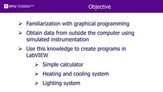
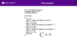
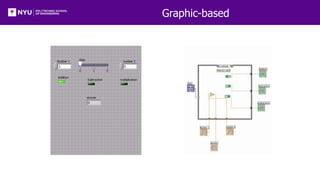
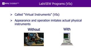
EG1003: Introduction to Engineering and Design
Introduction to LabVIEW
Overview
 Objective
 Background
 Materials
 Procedure
 Report / Presentation
 Closing
Objective
 Familiarization with graphical programming
 Obtain data from outside the computer using
simulated instrumentation
 Use this knowledge to create programs in
LabVIEW
 Simple calculator
 Heating and cooling system
 Lighting system
What is LabVIEW?
 Laboratory Virtual Instrument Engineering
Workbench
 Graphical programming language
 Used for data acquisition, instrument control,
and signal processing
 Based on G programming language
Text-based
Graphic-based
LabVIEW Programs (VIs)
 Called “Virtual Instruments” (VIs)
 Appearance and operation imitates actual physical
instruments
Without With
Applications in EG1003
 Heat Transfer and Thermal Insulation Lab
 Temperature Recording
 Electronic Filters Lab
 Oscilloscope (SignalExpress)
 Semester Long Project – Supermarket, Train
 Lighting system and heater/AC
 Security system
 Light sensors
 Switches rail paths
LabVIEW Interface
Front Panel - User Interface (UI),
where the program is controlled
and executed
Back Panel (Block Diagram) -
The internal circuit where the
program code is written
Controls and Indicators
Icon in back panel represents object in front panel
Color Representation
LabVIEW Tools
LabVIEW Functions (View > Functions)
Structures
 Allow programmer to produce conditional
statements or multiple outputs, based on input
 Example
 Case Structure
 Executes code based
on input value
NI-ELVIS Board
 National Instruments’ Educational Laboratory
Virtual Instrumentation Suite Board
 Interface that exchanges data (sends/receives)
between the computer and the outside world
References: See EG1003 Online Manual, National Instruments
documentation, and other LabVIEW oriented
websites (i.e. IIT’s LabVIEW for Dummies©)
Pattern and Pin activation
 Activate multiple pins
 Use compound arithmetic operator
 Add as many inputs as needed
 Click and drag the bottom to add inputs
 Link sum to Build Array
Materials
 Computer with LabVIEW
 NI-ELVIS Board
 Wires
Procedure
• Program 1:
Simple
Calculator
• Program 2:
Thermal
Control
• Program 3:
Lighting
System
Program 1: Simple Calculator VI
Create program simulating basic calculator
Able to add, subtract, and multiply
Procedure
• Program 1:
Simple
Calculator
• Program 2:
Thermal
Control
• Program 3:
Lighting
System
Program 1: Simple Calculator VI
Front panel of program must have:
 1 slide to control 3 different arithmetic operations
(add +; subtract -; multiply *)
 3 LED (Boolean) indicators to show which
arithmetic operation is selected
 Two numeric controls for inputting numbers
 One numeric indicator to display results
Back panel should have:
 A case statement to control arithmetic operations
Procedure
• Program 1:
Simple
Calculator
• Program 2:
Thermal
Control
• Program 3:
Lighting
System
Program 2: Thermal Control VI
 Home heating/cooling system
 Program requirements- Automatic Mode
 Regulate house air temperature
 AC is ON when temperature is greater than 80oF
 Heater is ON when the temperature is less than
60oF
 Heater and AC are OFF when temperature is
between 60oF and 80oF
 Program requirements- Manual Mode
Heater and AC power are controlled directly by user
(overrides automatic mode)
Procedure
• Program 1:
Simple
Calculator
• Program 2:
Thermal
Control
• Program 3:
Lighting
System
Program 2: Thermal Control VI
Front panel must have:
 3 LEDs
 AC on/off indicator
 Heater on/off indicator
 Manual operation on/off indicator
 3 switches for AC, heater and system operation
(automatic/manual)
 A temperature control represented by a
thermometer
Back panel should have:
 A Boolean case statement to control manual and
automatic operations
Procedure
• Program 1:
Simple
Calculator
• Program 2:
Thermal
Control
• Program 3:
Lighting
System
Program 3: Lighting System VI
 Simulate typical household lighting system
 Use Boolean indicators in conjunction with real
LEDs to illustrate operation
Procedure
• Program 1:
Simple
Calculator
• Program 2:
Thermal
Control
• Program 3:
Lighting
System
Program 3: Lighting System VI
Front panel must have:
 Main power on/off switch for all lights
 4 lights, each representing a different room
 Each light should have a separate on/off switch
Back panel should have:
 A “NI ELVISmx Digital Writer node” setup to
control LEDs through board
 A Boolean case for each LED
Real world
 Functional LED assembly (depict real lights)
Assignment: Report/Presentation
 Submit a Zip file with all LabVIEW programs (.vi)
 No Presentation for this Lab
 Individual report
 Title page
 Discussion topics in the manual
 Scan in data and lab notes (ask TA for assistance)
Closing
 Have all lab notes signed by TA
 Each team member should have turn using
software
 Save Heating and Cooling VI – to be used in a
future lab session
 Submit all work electronically
 Return all unused materials to TA

LabVIEW.pptx

  • 1.
    EG1003: Introduction toEngineering and Design Introduction to LabVIEW
  • 2.
    Overview  Objective  Background Materials  Procedure  Report / Presentation  Closing
  • 3.
    Objective  Familiarization withgraphical programming  Obtain data from outside the computer using simulated instrumentation  Use this knowledge to create programs in LabVIEW  Simple calculator  Heating and cooling system  Lighting system
  • 4.
    What is LabVIEW? Laboratory Virtual Instrument Engineering Workbench  Graphical programming language  Used for data acquisition, instrument control, and signal processing  Based on G programming language
  • 5.
  • 6.
  • 7.
    LabVIEW Programs (VIs) Called “Virtual Instruments” (VIs)  Appearance and operation imitates actual physical instruments Without With
  • 8.
    Applications in EG1003 Heat Transfer and Thermal Insulation Lab  Temperature Recording  Electronic Filters Lab  Oscilloscope (SignalExpress)  Semester Long Project – Supermarket, Train  Lighting system and heater/AC  Security system  Light sensors  Switches rail paths
  • 9.
    LabVIEW Interface Front Panel- User Interface (UI), where the program is controlled and executed Back Panel (Block Diagram) - The internal circuit where the program code is written
  • 10.
    Controls and Indicators Iconin back panel represents object in front panel
  • 11.
  • 12.
  • 13.
  • 14.
    Structures  Allow programmerto produce conditional statements or multiple outputs, based on input  Example  Case Structure  Executes code based on input value
  • 15.
    NI-ELVIS Board  NationalInstruments’ Educational Laboratory Virtual Instrumentation Suite Board  Interface that exchanges data (sends/receives) between the computer and the outside world References: See EG1003 Online Manual, National Instruments documentation, and other LabVIEW oriented websites (i.e. IIT’s LabVIEW for Dummies©)
  • 16.
    Pattern and Pinactivation  Activate multiple pins  Use compound arithmetic operator  Add as many inputs as needed  Click and drag the bottom to add inputs  Link sum to Build Array
  • 17.
    Materials  Computer withLabVIEW  NI-ELVIS Board  Wires
  • 18.
    Procedure • Program 1: Simple Calculator •Program 2: Thermal Control • Program 3: Lighting System Program 1: Simple Calculator VI Create program simulating basic calculator Able to add, subtract, and multiply
  • 19.
    Procedure • Program 1: Simple Calculator •Program 2: Thermal Control • Program 3: Lighting System Program 1: Simple Calculator VI Front panel of program must have:  1 slide to control 3 different arithmetic operations (add +; subtract -; multiply *)  3 LED (Boolean) indicators to show which arithmetic operation is selected  Two numeric controls for inputting numbers  One numeric indicator to display results Back panel should have:  A case statement to control arithmetic operations
  • 20.
    Procedure • Program 1: Simple Calculator •Program 2: Thermal Control • Program 3: Lighting System Program 2: Thermal Control VI  Home heating/cooling system  Program requirements- Automatic Mode  Regulate house air temperature  AC is ON when temperature is greater than 80oF  Heater is ON when the temperature is less than 60oF  Heater and AC are OFF when temperature is between 60oF and 80oF  Program requirements- Manual Mode Heater and AC power are controlled directly by user (overrides automatic mode)
  • 21.
    Procedure • Program 1: Simple Calculator •Program 2: Thermal Control • Program 3: Lighting System Program 2: Thermal Control VI Front panel must have:  3 LEDs  AC on/off indicator  Heater on/off indicator  Manual operation on/off indicator  3 switches for AC, heater and system operation (automatic/manual)  A temperature control represented by a thermometer Back panel should have:  A Boolean case statement to control manual and automatic operations
  • 22.
    Procedure • Program 1: Simple Calculator •Program 2: Thermal Control • Program 3: Lighting System Program 3: Lighting System VI  Simulate typical household lighting system  Use Boolean indicators in conjunction with real LEDs to illustrate operation
  • 23.
    Procedure • Program 1: Simple Calculator •Program 2: Thermal Control • Program 3: Lighting System Program 3: Lighting System VI Front panel must have:  Main power on/off switch for all lights  4 lights, each representing a different room  Each light should have a separate on/off switch Back panel should have:  A “NI ELVISmx Digital Writer node” setup to control LEDs through board  A Boolean case for each LED Real world  Functional LED assembly (depict real lights)
  • 24.
    Assignment: Report/Presentation  Submita Zip file with all LabVIEW programs (.vi)  No Presentation for this Lab  Individual report  Title page  Discussion topics in the manual  Scan in data and lab notes (ask TA for assistance)
  • 25.
    Closing  Have alllab notes signed by TA  Each team member should have turn using software  Save Heating and Cooling VI – to be used in a future lab session  Submit all work electronically  Return all unused materials to TA