Downloaded 881 times
![COLLEGE OF ENGINEERING AND TECHNOLOGY , AKOLA
Sant Gadge Baba Amravati University, Amravati
[2015-2016]
DEPARTMENT OF MECHANICAL ENGINEERING
Presented By…
Nivrati A. Malve
Guided By..
Prof. Y. P. Tidke](https://image.slidesharecdn.com/kersmalveppt-151020052935-lva1-app6891/85/Kinetic-energy-recovery-system-ppt-1-320.jpg)
![COLLEGE OF ENGINEERING AND TECHNOLOGY , AKOLA
Sant Gadge Baba Amravati University, Amravati
[2015-2016]
DEPARTMENT OF MECHANICAL ENGINEERING
Presented By…
Nivrati A. Malve
Guided By..
Prof. Y. P. Tidke](https://image.slidesharecdn.com/kersmalveppt-151020052935-lva1-app6891/75/Kinetic-energy-recovery-system-ppt-1-2048.jpg)

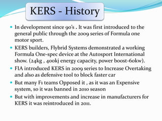
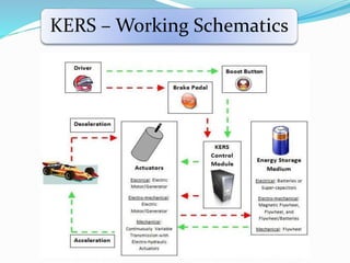
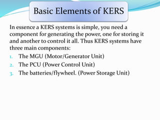
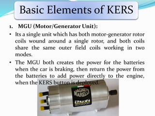
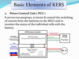
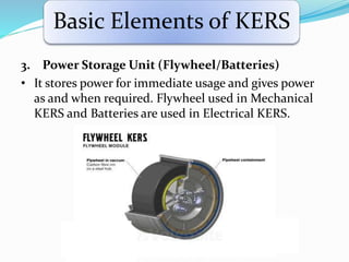
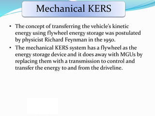
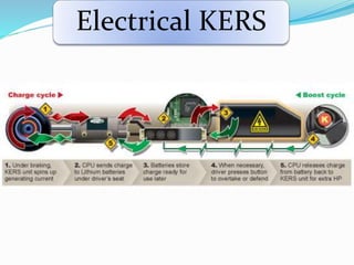
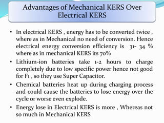
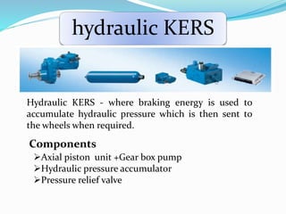
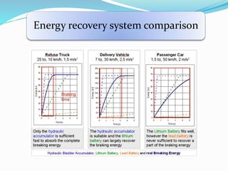
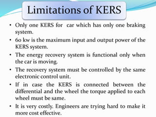


This document discusses Kinetic Energy Recovery Systems (KERS) used in vehicles. It begins with an introduction to KERS, explaining that it recovers kinetic energy lost during braking and stores it to provide an acceleration boost. It then covers the history, working schematics, basic elements, types (mechanical, electrical, hydraulic), advantages, and applications of KERS. The basic elements include a motor/generator unit, power control unit, and energy storage component like batteries or a flywheel. Mechanical KERS stores energy in a flywheel while electrical KERS uses batteries. KERS provides benefits like reduced emissions and improved performance but also has limitations regarding costs, power capacity, and applicability only during vehicle movement.


