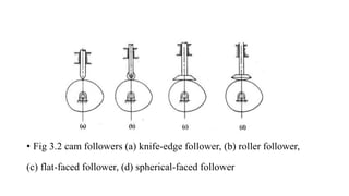
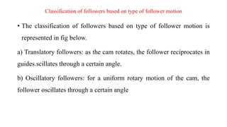
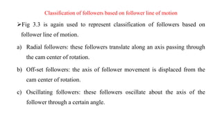
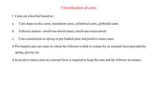
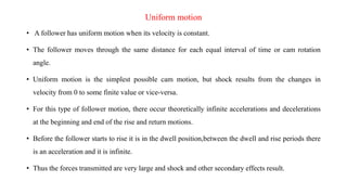
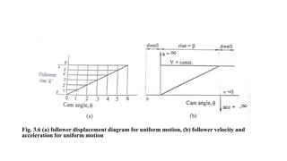
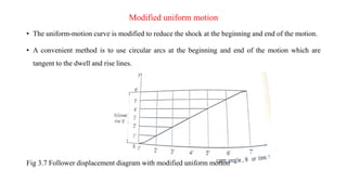
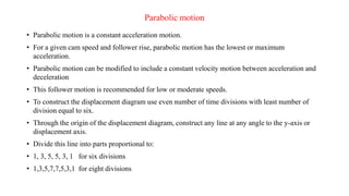
A cam is a mechanical device used to convert rotational motion into linear or oscillating motion. It works through direct contact with a follower. Cams can be classified based on the follower's surface, type of motion, and position relative to the cam's center. Common follower surfaces include knife-edge, roller, and flat or spherical faces. Follower motion may be translatory, oscillatory, or a combination. The document provides examples of displacement diagrams and motions including uniform, modified uniform, parabolic, simple harmonic, and cycloidal. It also defines cam nomenclature and describes the process for designing a cam profile based on a given follower motion specification.
Cosmetic shop management system project report.pdfKamal Acharya
Buying new cosmetic products is difficult. It can even be scary for those who have sensitive skin and are prone to skin trouble. The information needed to alleviate this problem is on the back of each product, but it's thought to interpret those ingredient lists unless you have a background in chemistry.
Instead of buying and hoping for the best, we can use data science to help us predict which products may be good fits for us. It includes various function programs to do the above mentioned tasks.
Data file handling has been effectively used in the program.
The automated cosmetic shop management system should deal with the automation of general workflow and administration process of the shop. The main processes of the system focus on customer's request where the system is able to search the most appropriate products and deliver it to the customers. It should help the employees to quickly identify the list of cosmetic product that have reached the minimum quantity and also keep a track of expired date for each cosmetic product. It should help the employees to find the rack number in which the product is placed.It is also Faster and more efficient way.
Quality defects in TMT Bars, Possible causes and Potential Solutions.PrashantGoswami42
Maintaining high-quality standards in the production of TMT bars is crucial for ensuring structural integrity in construction. Addressing common defects through careful monitoring, standardized processes, and advanced technology can significantly improve the quality of TMT bars. Continuous training and adherence to quality control measures will also play a pivotal role in minimizing these defects.
NO1 Uk best vashikaran specialist in delhi vashikaran baba near me online vas...Amil Baba Dawood bangali
Contact with Dawood Bhai Just call on +92322-6382012 and we'll help you. We'll solve all your problems within 12 to 24 hours and with 101% guarantee and with astrology systematic. If you want to take any personal or professional advice then also you can call us on +92322-6382012 , ONLINE LOVE PROBLEM & Other all types of Daily Life Problem's.Then CALL or WHATSAPP us on +92322-6382012 and Get all these problems solutions here by Amil Baba DAWOOD BANGALI
#vashikaranspecialist #astrologer #palmistry #amliyaat #taweez #manpasandshadi #horoscope #spiritual #lovelife #lovespell #marriagespell#aamilbabainpakistan #amilbabainkarachi #powerfullblackmagicspell #kalajadumantarspecialist #realamilbaba #AmilbabainPakistan #astrologerincanada #astrologerindubai #lovespellsmaster #kalajaduspecialist #lovespellsthatwork #aamilbabainlahore#blackmagicformarriage #aamilbaba #kalajadu #kalailam #taweez #wazifaexpert #jadumantar #vashikaranspecialist #astrologer #palmistry #amliyaat #taweez #manpasandshadi #horoscope #spiritual #lovelife #lovespell #marriagespell#aamilbabainpakistan #amilbabainkarachi #powerfullblackmagicspell #kalajadumantarspecialist #realamilbaba #AmilbabainPakistan #astrologerincanada #astrologerindubai #lovespellsmaster #kalajaduspecialist #lovespellsthatwork #aamilbabainlahore #blackmagicforlove #blackmagicformarriage #aamilbaba #kalajadu #kalailam #taweez #wazifaexpert #jadumantar #vashikaranspecialist #astrologer #palmistry #amliyaat #taweez #manpasandshadi #horoscope #spiritual #lovelife #lovespell #marriagespell#aamilbabainpakistan #amilbabainkarachi #powerfullblackmagicspell #kalajadumantarspecialist #realamilbaba #AmilbabainPakistan #astrologerincanada #astrologerindubai #lovespellsmaster #kalajaduspecialist #lovespellsthatwork #aamilbabainlahore #Amilbabainuk #amilbabainspain #amilbabaindubai #Amilbabainnorway #amilbabainkrachi #amilbabainlahore #amilbabaingujranwalan #amilbabainislamabad
Overview of the fundamental roles in Hydropower generation and the components involved in wider Electrical Engineering.
This paper presents the design and construction of hydroelectric dams from the hydrologist’s survey of the valley before construction, all aspects and involved disciplines, fluid dynamics, structural engineering, generation and mains frequency regulation to the very transmission of power through the network in the United Kingdom.
Author: Robbie Edward Sayers
Collaborators and co editors: Charlie Sims and Connor Healey.
(C) 2024 Robbie E. Sayers
Explore the innovative world of trenchless pipe repair with our comprehensive guide, "The Benefits and Techniques of Trenchless Pipe Repair." This document delves into the modern methods of repairing underground pipes without the need for extensive excavation, highlighting the numerous advantages and the latest techniques used in the industry.
Learn about the cost savings, reduced environmental impact, and minimal disruption associated with trenchless technology. Discover detailed explanations of popular techniques such as pipe bursting, cured-in-place pipe (CIPP) lining, and directional drilling. Understand how these methods can be applied to various types of infrastructure, from residential plumbing to large-scale municipal systems.
Ideal for homeowners, contractors, engineers, and anyone interested in modern plumbing solutions, this guide provides valuable insights into why trenchless pipe repair is becoming the preferred choice for pipe rehabilitation. Stay informed about the latest advancements and best practices in the field.
Immunizing Image Classifiers Against Localized Adversary Attacksgerogepatton
This paper addresses the vulnerability of deep learning models, particularly convolutional neural networks
(CNN)s, to adversarial attacks and presents a proactive training technique designed to counter them. We
introduce a novel volumization algorithm, which transforms 2D images into 3D volumetric representations.
When combined with 3D convolution and deep curriculum learning optimization (CLO), itsignificantly improves
the immunity of models against localized universal attacks by up to 40%. We evaluate our proposed approach
using contemporary CNN architectures and the modified Canadian Institute for Advanced Research (CIFAR-10
and CIFAR-100) and ImageNet Large Scale Visual Recognition Challenge (ILSVRC12) datasets, showcasing
accuracy improvements over previous techniques. The results indicate that the combination of the volumetric
input and curriculum learning holds significant promise for mitigating adversarial attacks without necessitating
adversary training.
TECHNICAL TRAINING MANUAL GENERAL FAMILIARIZATION COURSEDuvanRamosGarzon1
AIRCRAFT GENERAL
The Single Aisle is the most advanced family aircraft in service today, with fly-by-wire flight controls.
The A318, A319, A320 and A321 are twin-engine subsonic medium range aircraft.
The family offers a choice of engines
Student information management system project report ii.pdfKamal Acharya
Our project explains about the student management. This project mainly explains the various actions related to student details. This project shows some ease in adding, editing and deleting the student details. It also provides a less time consuming process for viewing, adding, editing and deleting the marks of the students.
Industrial Training at Shahjalal Fertilizer Company Limited (SFCL)MdTanvirMahtab2
This presentation is about the working procedure of Shahjalal Fertilizer Company Limited (SFCL). A Govt. owned Company of Bangladesh Chemical Industries Corporation under Ministry of Industries.
CFD Simulation of By-pass Flow in a HRSG module by R&R Consult.pptxR&R Consult
CFD analysis is incredibly effective at solving mysteries and improving the performance of complex systems!
Here's a great example: At a large natural gas-fired power plant, where they use waste heat to generate steam and energy, they were puzzled that their boiler wasn't producing as much steam as expected.
R&R and Tetra Engineering Group Inc. were asked to solve the issue with reduced steam production.
An inspection had shown that a significant amount of hot flue gas was bypassing the boiler tubes, where the heat was supposed to be transferred.
R&R Consult conducted a CFD analysis, which revealed that 6.3% of the flue gas was bypassing the boiler tubes without transferring heat. The analysis also showed that the flue gas was instead being directed along the sides of the boiler and between the modules that were supposed to capture the heat. This was the cause of the reduced performance.
Based on our results, Tetra Engineering installed covering plates to reduce the bypass flow. This improved the boiler's performance and increased electricity production.
It is always satisfying when we can help solve complex challenges like this. Do your systems also need a check-up or optimization? Give us a call!
Work done in cooperation with James Malloy and David Moelling from Tetra Engineering.
More examples of our work https://www.r-r-consult.dk/en/cases-en/
CFD Simulation of By-pass Flow in a HRSG module by R&R Consult.pptx
ch3 cams and follower.pdf
1. Cams
• A cam is an irregular-shaped mechanical member for transmitting a desired motion to another
element, known as the follower, by direct contact.
• The cam and the follower have a line contact and constitute a higher pair.
• A cam may remain stationary, translate or rotate while the follower may translate or oscillate.
• Usually cams rotate at constant angular speed.
• Cams provide a means of achieving any desired follower motion and are used in many
machine.
• They are widely used for operating the inlet and exhaust valves of internal combustion
engines, and are extensively used in machine tools, mechanical computers, instruments and
many other applications.
2. Classification of Followers
• Followers may be classified based on the following
1. Construction of the surface of contact
2. Type of follower motion
3. Location of line of motion with respect to center of cam
3. classification of followers based on surface of contact
• The classification of followers based on follower surface of contact
a) A knife-edge follower: in such a follower a sharp, knife-edge is in contact with the
cam. Such followers produce excessive cam wear, so they are of little practical use.
b) A roller follower: A cylindrical roller, held by a pin to the follower assembly, is in
contact with the cam. At low speeds pure rolling contact is possible but at high speeds
some sliding can also occur. These types of followers reduce wear of the cam surface at
high peripheral speeds.
c) A flat-faced follower: as the name implies, flat face is in contact with the cam. These
types of followers cause high surface stress and reduce and reduce this stress, the flat
face is modified to a spherical surface with a large radius.
5. Classification of followers based on type of follower motion
• The classification of followers based on type of follower motion is
represented in fig below.
a) Translatory followers: as the cam rotates, the follower reciprocates in
guides.scillates through a certain angle.
b) Oscillatory followers: for a uniform rotary motion of the cam, the
follower oscillates through a certain angle
6. Classification of followers based on follower line of motion
Fig 3.3 is again used to represent classification of followers based on
follower line of motion.
a) Radial followers: these followers translate along an axis passing through
the cam center of rotation.
b) Off-set followers: the axis of follower movement is displaced from the
cam center of rotation.
c) Oscillating followers: these followers oscillate about the axis of the
follower through a certain angle.
7. Classification of cams
• Cams are classified based on:
a. Cam shape as disc cams, translation cams, cylindrical cams, globoidal cams
b. Follower motion:- dwell-rise-dwell-return, dwell-rise-return-dwell
c. Cam construction as spring or pre-loaded cams and positive return cams.
Pre-loaded cams are cams in which the follower is held in contact by an external force provided by
spring, gravity etc.
In positive return cams no external force is required to keep the cam and the follower in contact.
8. Cam Nomenclature
• Base circle is the smallest circle that can be drawn about the center of cam rotation and through the
cam surface. Its size determines the size of the cam.
• Cam profile: The outer surface of the disc cam.
• Trace point: It is a point on the follower, and its motion describes the movement of the follower. It
is used to generate the pitch curve.
• Pitch curve : The path generated by the trace point as the follower is rotated about a stationery
cam.
• Prime circle: The smallest circle from the cam center through the pitch curve
9. • Pressure angle: The angle between the direction of the follower movement and the normal to the
pitch curve.
• Pitch point: Pitch point corresponds to the point of maximum pressure angle.
• Pitch circle: A circle drawn from the cam center and passes through the pitch point is called Pitch
circle
• Stroke: The greatest distance or angle through which the follower moves or rotates
• Lift or Rise is the maximum travel of the follower from the lowest position to the top most
position.
11. Displacement Diagram
• Before a cam profile is determined, the motion of the follower in
accordance to the requirements of the system must be selected.
• The follower motion is indicated on the displacement diagram.
• The displacement diagram has as an abscissa the cam rotation angle, and the
ordinate is the follower travel in millimeters.
• The divisions of the abscissa are identified by the station point numbers.
• These divisions can be in degrees or in seconds.
12. The displacement diagram identifies the following motion characteristics:
The rise: motion of the follower away from the cam center
The dwells: those periods during which the follower is at rest, and
The return: motion of the follower toward the cam center.
13. Types of follower motion
• The first step in the design of a cam curve consists in constructing the associated displacement
diagram.
• The follower motion might be a standard or a custom type.
• Some of the standard motions are : uniform, modified uniform, simple harmonic, parabolic and
cycloidal.
• Ordinarily, a cam will have one or more rises and, generally, as many returns as rises.
• Dwell periods might not be necessary.
• The rises, dwells and returns must suitably be distributed around the periphery of the cam.
• The periods of these occupy the time of one rotation of the cam.
14. Uniform motion
• A follower has uniform motion when its velocity is constant.
• The follower moves through the same distance for each equal interval of time or cam rotation
angle.
• Uniform motion is the simplest possible cam motion, but shock results from the changes in
velocity from 0 to some finite value or vice-versa.
• For this type of follower motion, there occur theoretically infinite accelerations and decelerations
at the beginning and end of the rise and return motions.
• Before the follower starts to rise it is in the dwell position,between the dwell and rise periods there
is an acceleration and it is infinite.
• Thus the forces transmitted are very large and shock and other secondary effects result.
15. Fig. 3.6 (a) follower displacement diagram for uniform motion, (b) follower velocity and
acceleration for uniform motion
16. Modified uniform motion
• The uniform-motion curve is modified to reduce the shock at the beginning and end of the motion.
• A convenient method is to use circular arcs at the beginning and end of the motion which are
tangent to the dwell and rise lines.
Fig 3.7 Follower displacement diagram with modified uniform motion
17. Parabolic motion
• Parabolic motion is a constant acceleration motion.
• For a given cam speed and follower rise, parabolic motion has the lowest or maximum
acceleration.
• Parabolic motion can be modified to include a constant velocity motion between acceleration and
deceleration
• This follower motion is recommended for low or moderate speeds.
• To construct the displacement diagram use even number of time divisions with least number of
division equal to six.
• Through the origin of the displacement diagram, construct any line at any angle to the y-axis or
displacement axis.
• Divide this line into parts proportional to:
• 1, 3, 5, 5, 3, 1 for six divisions
• 1,3,5,7,7,5,3,1 for eight divisions
18. • Connect the last division with the point marked on the displacement axis corresponding to the rise.
• Through the other divisions draw lines parallel to this line to obtain the follower displacement for each
divisions of cam rotation.
• Fig 3.9. (a) Follower displacement with parabolic motion. (b) follower parabolic motion characteristics
19. Simple Harmonic motion
• The simple harmonic motion is obtained graphically by construction a semi-circle on the rise of the
displacement diagram and then dividing the semi circle into as many equal parts as are used for
the time axis (or cam angle).
• Fig 3.9 (a) Follower displacement for parabolic motion
• (b) follower motion characteristics for parabolic motion
20. Cycloidal Motion
• In order to avoid infinite jerk between rise , return and dwell motions, cycloidal motion is often
employed.
• Cycloidal motion is a motion which has a zero acceleration at the beginning and end of the rise.
• A cycloid is defined as the locus of a point on a circle that rolls on a straight line.
• For cam rotation angle the displacement of the cycloidal motion is the rise AC=d, which must be
equal to the circumference of the rolling circle. Thus
2𝜋𝑟 = 𝑑
From which the radius of the rolling circle r is obtained to be
𝑟 =
𝑑
2𝜋
21. • To construct the displacement diagram for the cycloidal motion.
1. Draw a circle with center B
2. The circle is then divided into as many equal parts as used for the cam angle axis.
3. The points on the circle are projected to a vertical line through B as shown on the figure.
Through these points lines are drawn parallel to AB which intersect with vertical lines drawn
through the divisions on the cam angle axis.
4. The intersection points are joined by a smooth curve to give the cycloidal motion displacement.
22. Example 1
1. Draw the displacement diagram for a radial roller follower that rises 50mm from its lowest
position with a simple harmonic motion in 1/3 of a revolution, dwells for 1/12 of a revolution
and then returns to its lowest position in 1/6 of a revolution with simple harmonic motion to
remain at rest for the rest of the revolution. Assume of roller diameter of 20mm, and minimum
cam radius of 25mm. For the above motion of the follower, lay out the cam profile that would
produce the required motion.
Solution
Follower rise d=50mm
Cam angle for the rise motion 𝛽 =
2𝜋
3
rad =1200
Dwell angle =
𝜋
6
=300
23. Cam angle for the return motion 𝛽′
=
𝜋
3
rad =600
Dwell angle after the return motion =
5𝜋
12
rad=1500
The displacement diagram is drawn to a convenient scale. The procedure of construction is as followers.
1) Draw the horizontal straight line OPQRS with a convenient length. Preferably OS= development of
the prime circle. OPQRS= 3600
Divide the line OS into segments where
OP=1200
, cam angle corresponding to the rise of the follower.
PQ=300
, cam angle Corresponding to the dwell of the follower in its lifted position.
QR= 600
, cam angle corresponding to the return of the follower.
RS= 1500
, cam angle corresponding to the dwell of the follower in its lowest position
24. 2) Draw a Vertical line through O equal to the follower rise.
𝑂𝑓′=50mm
3) Divide the cam angle corresponding to the rise and return motions into equal even number of
divisions, in this case six divisions.
We obtain 0,1,2,3,4,5,6 for the rise and 0′
, 1′
, 2′
, 3′
, 4′
, 5′
, 6′
for the return.
4) With 𝑂𝑓′
as diameter draw a semi-circle and divide it into equal divisions, the number being equal
to that in step 3. this locates a, b,c,d,e, and f. project these points on to the vertical lines through 0, 1,
2, etc and 0′, 1′, 2′, etc. the projections give points A,B,C,D,E,F on the rise and 𝐴′, 𝐵′, 𝐶′, 𝐷′, 𝐸′, 𝐹′
on the return.
5) Join points A,B,C,D,E,F by a smooth curve and so also 𝐴′, 𝐵′, 𝐶′, 𝐷′, 𝐸′, 𝐹′ to obtain the
displacement diagram.
25. The cam curve is laid out according to the following procedure of construction.
1) Draw the prime circle with center C and radius CO.
CO is set equal to minimum radius of cam plus radius of roller.
CO= 25+10mm=35mm
2) Draw
Angle OCP =1200 to represent the follower rise,
Angle PCQ= 300 to represent the dwell of the follower in the outermost position
Angle=QCR=600 to represent the return of the follower to its lowest position
Angles OCP and QCR are divide into even number of division to match the number of divisions in
the displacement diagram. In this case there are six divisions.
26. 3) From the displacement diagram, o, 𝑎′
, 𝑏′
, 𝑐′
, 𝑑′
,and 𝑓′
are transferred to a vertical line through
the trace point o and the cam center C. these points are rotated to intersect with the rise divisions and
return divisions at 1′, 2′, 3′, 4′, 5′, 6′ and 7′, 8′, 9′, 10′, 11′, respectively. With these points as
center, draw the position of the roller.
4) Join points 0, 1′, 2′,…. 11′ to obtain the pitch curve. Draw tangent to the roller position of the
roller.