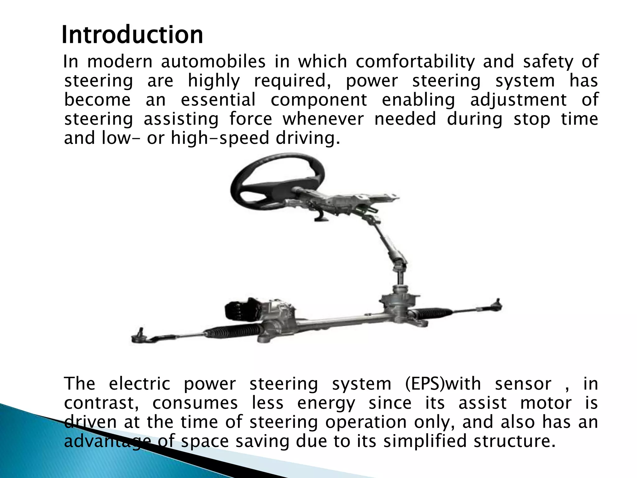
1) The document presents on the development of an automatic steering mechanism using a sensor. It describes improving the steerability and quietness of an electric power steering system sensor.
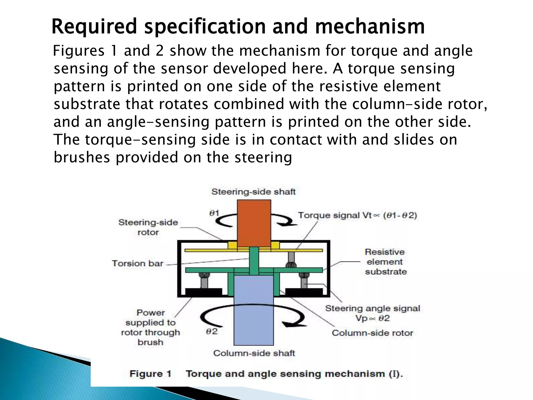
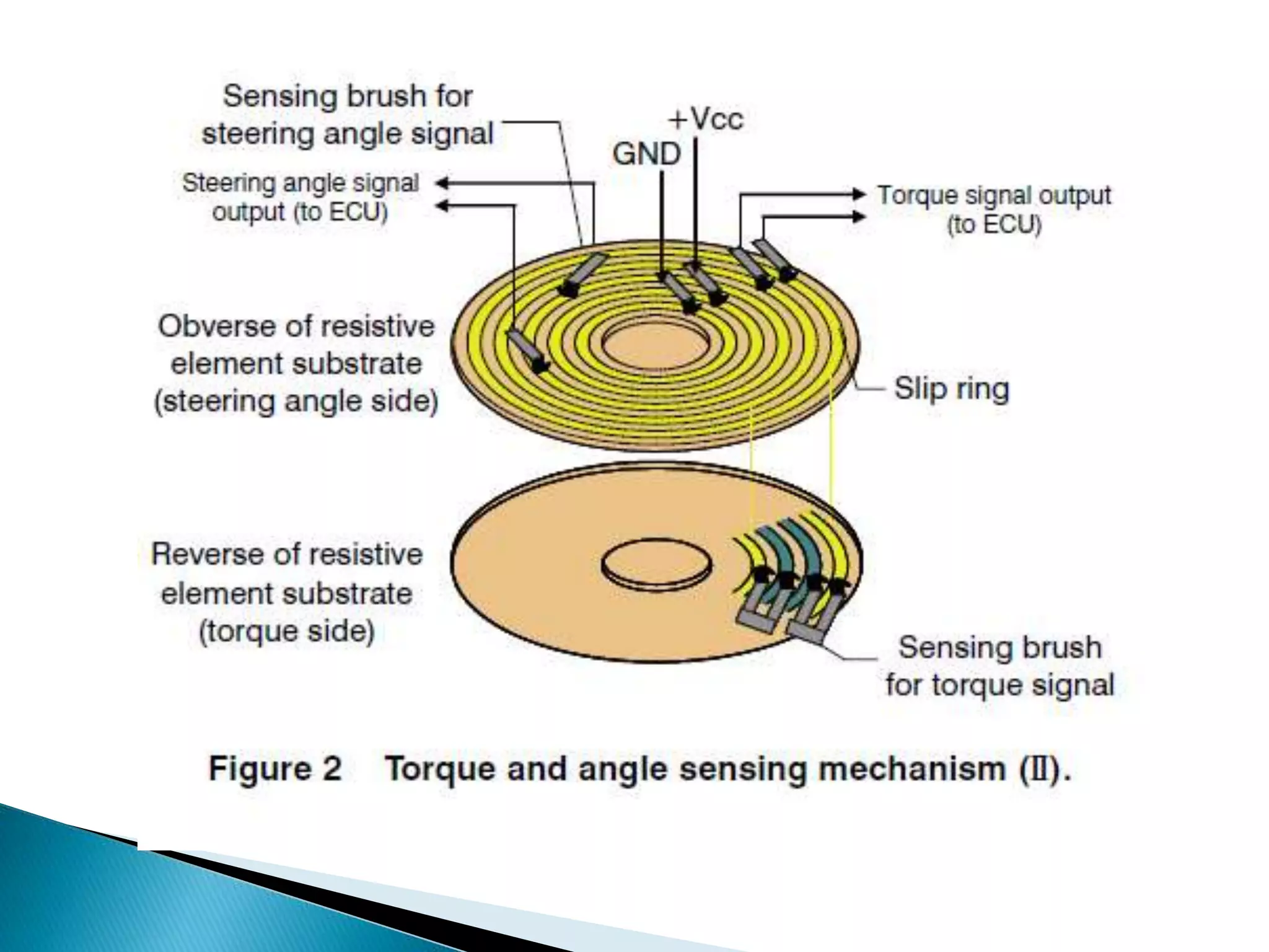
2) The sensor measures torque and angle of the steering shaft using resistive patterns. Factors that can degrade responsiveness like backlash and friction were reduced.
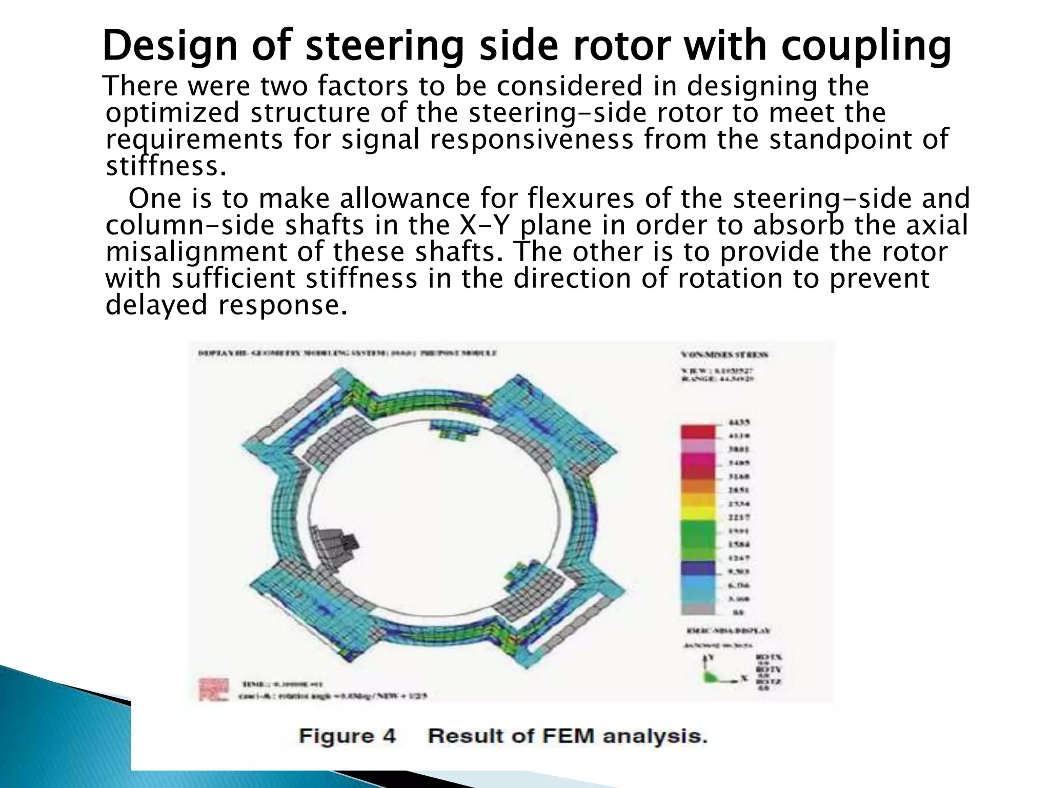
3) The steering-side rotor design allowed for shaft misalignment while providing sufficient stiffness for responsive signals. Future work will further reduce costs and improve performance of the mass produced sensor.


![References
[1] Automotive testing technology international: Awards
2007 special issue, Nov/Dec 2007.
[2] Omead Amidi. Integrated mobile robot control.
Technical Report CMU-RI-TR-90-17, Carnegie Mellon
University
Robotics Institute, 1990.
[3] Eduardo F. Camacho and Carlos Bordons. Model
Predictive Control. Spinger, 2004.
[4] Stefan F. Campbell. Steering control of an
autonomous ground vehicle with application to the
DARPA urban
challenge. Master’s thesis, Massachusetts Institute of
Technology, 2007.](https://image.slidesharecdn.com/rupeshk10741majorassigonicengine-160510163617/75/k10741-major-assig-on-ic-engine-10-2048.jpg)