Download to read offline
![International Research Journal of Engineering and Technology (IRJET) e-ISSN: 2395-0056
Volume: 05 Issue: 03 | Mar-2018 www.irjet.net p-ISSN: 2395-0072
© 2018, IRJET | Impact Factor value: 6.171 | ISO 9001:2008 Certified Journal | Page 3224
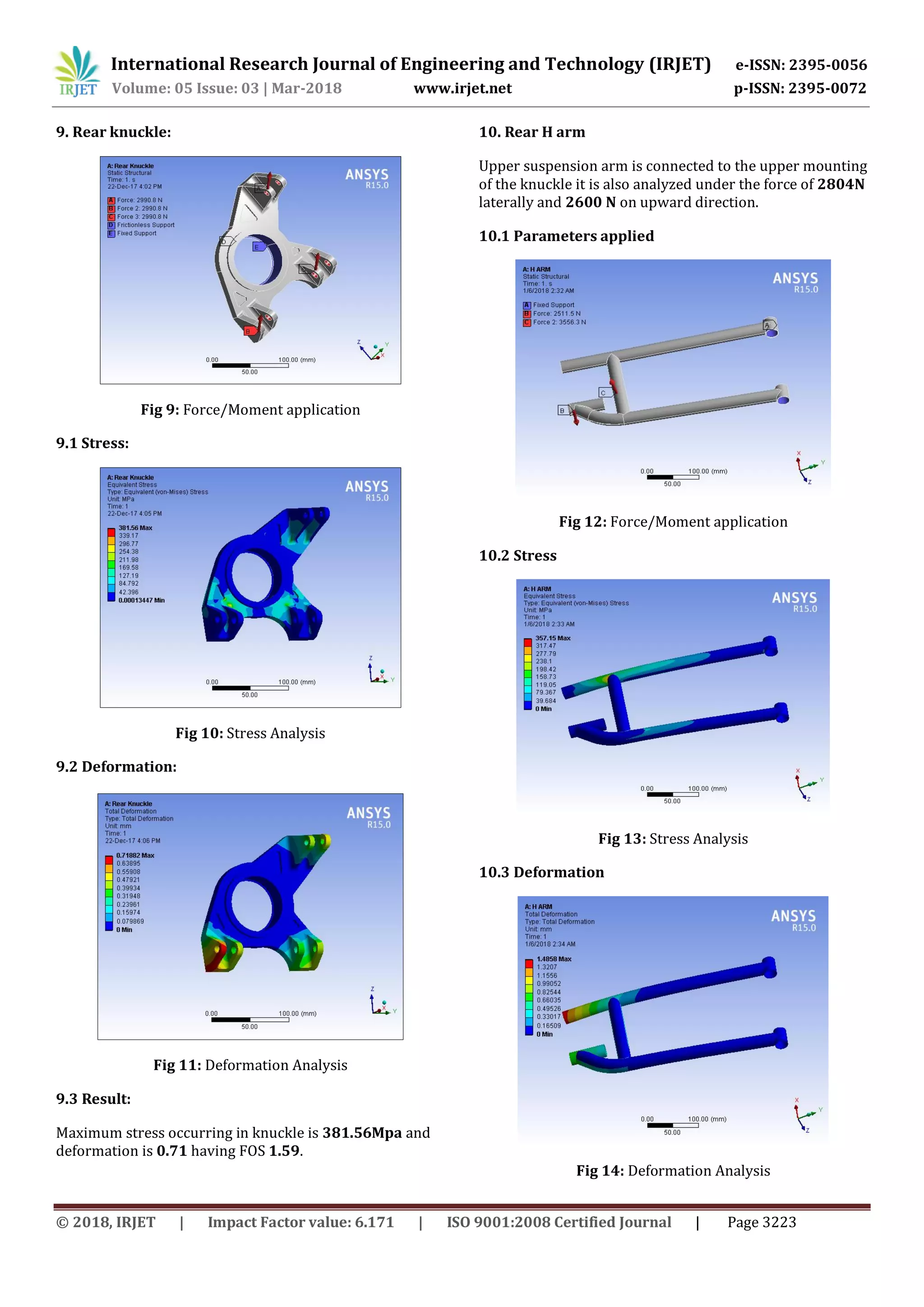
10.4 Result
The max stress that acts on the arms is about 357.15MPa
and max deformation is about 1.4858mm.
11. CONCLUSION
Suspension Deals with three C’s comfort, contact, control.
The agenda for designing the suspension wasto enhancethe
dynamic stability of an ATV. The Front and Rear geometries
were designed by using Lotus software with the help of
CatiaV5 and analysis was carried out by the software‘Ansys’.
The suspension parameters like Ground clearances,
Wheelbase, Track width and other dynamic parameter such
as Camber gain, toe gain etc. kept optimum so as to get
minimum force interaction with the tire. Thus with Double
Wishbone and H-arm linkage system the ATV was designed
and analyzed successfully.
12. REFERENCES
[1] RACE CAR VEHICLE DYNAMICS- Milliken and Milliken
[2] GILLIPSIE’S FUNDAMENTAL OF VEHICLE DYNAMICS
[3] TUNE TO WIN- Carroll Smith
[4] LOTUS – To design Suspension geometry
[5] ANSYS- To analyse the forces on the components.](https://image.slidesharecdn.com/irjet-v5i3759-190204040046/75/IRJET-Dynamic-Analysis-of-the-Front-and-Rear-Suspension-System-of-an-All-Terrain-Vehicle-9-2048.jpg)

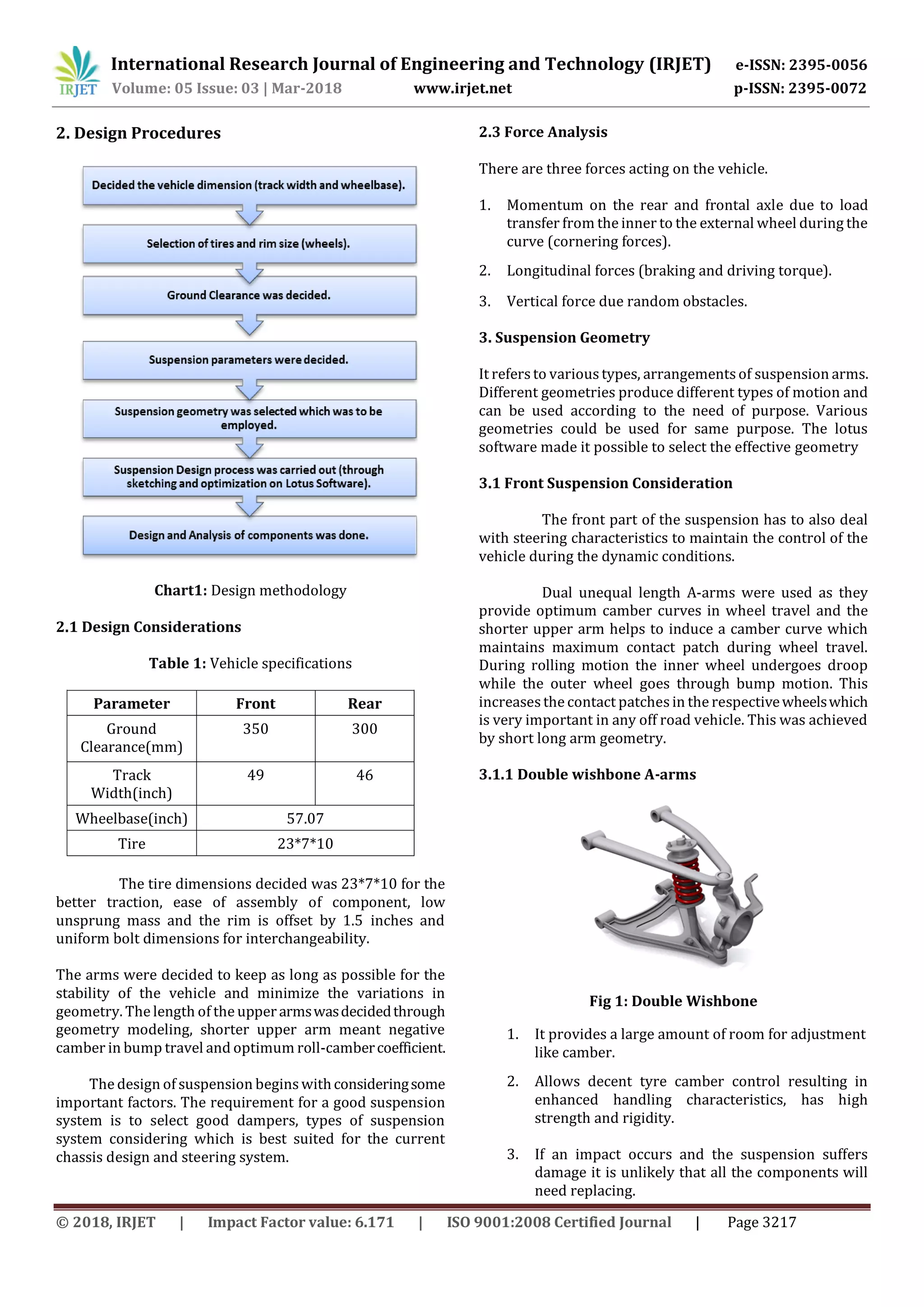
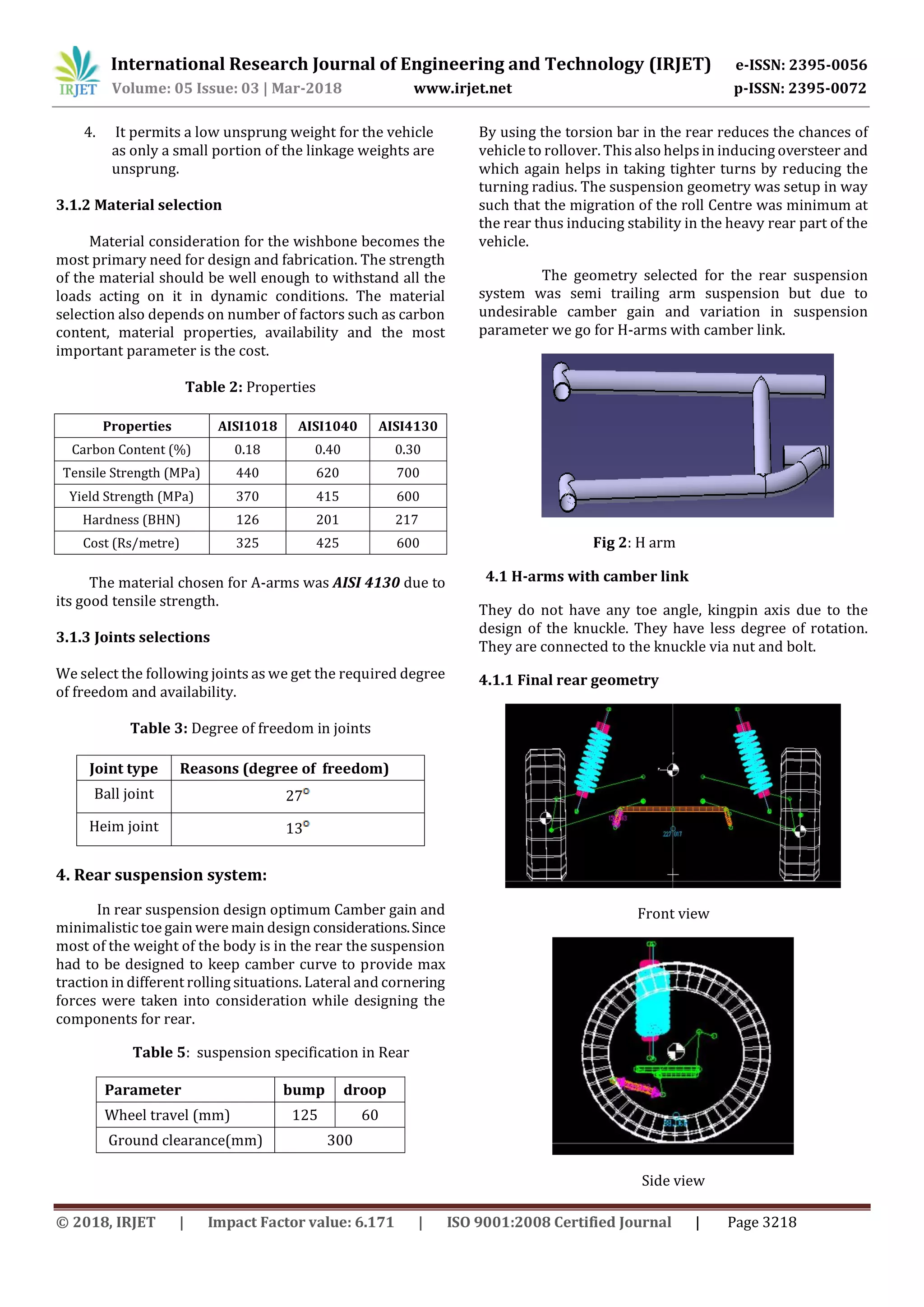
This document describes the design and analysis of the front and rear suspension systems for an all-terrain vehicle (ATV). It discusses using a double wishbone suspension in the front for steering control and an H-arm suspension in the rear for load bearing capacity and control of camber and toe. The design process considers factors like geometry, material selection, force analysis, and damper and spring selection and tuning. The goals of the suspension design are to provide maximum traction, control, comfort, and stability over rough terrain.