The document provides safety instructions and operating precautions for LS Variable Frequency Drives. It begins with warnings to follow all safety instructions to prevent accidents and hazards. Throughout the document, warnings identify potential hazards and cautions identify shock hazards. The document outlines proper installation, wiring, operation and maintenance of the drives, including instructions to always install safety devices and operate with dry hands. It provides operating precautions regarding handling, wiring, trial runs, and maintenance to prevent injuries and equipment damage.


![1-1
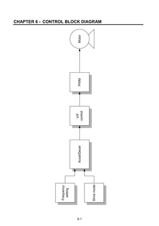
CHAPTER 1 - BASIC INFORMATION & PRECAUTIONS
1.1Important precautions
Unpacking and
inspection
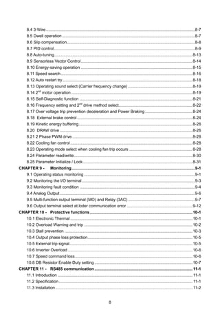
Inspect the inverter for any damage that may have occurred during shipping.
To verify the inverter unit is the correct one for the application you need,
check the inverter type, output ratings on the nameplate and the inverter is
intact.
SV 075 iG5A - 2 (N)
LSInverter
Motor rating
Series
Name
Input power Keypad
004 0.4 [kW]
iG5A
1
Single Phase
200~230[V]
NON loader I/O
Products
008 0.75 [kW]
015 1.5 [kW]
022 2.2 [kW]
037 3.7 [kW]
2
Three Phase
200~230[V]
040 4.0 [kW]
055 5.5 [kW]
075 7.5 [kW]
110 11.0[kW]
4
Three Phase
380~480[V]
150 15.0[kW]
185 18.5[kW]
220 22.0[kW]
Accessories
If you have found any discrepancy, damage, etc., contact your sales
representative.
Preparations
of instruments
and parts
required for
operation
Instruments and parts to be prepared depend on how the inverter is operated.
Prepare equipment and parts as necessary.
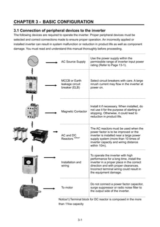
Installation To operate the inverter with high performance for a long time, install the inverter
in a proper place in the correct direction and with proper clearances
Wiring Connect the power supply, motor and operation signals (control signals) to the
terminal block. Note that incorrect connection may damage the inverter and
peripheral devices
Input power rating
Inverter Type
Output Power Rating
Rated output current, frequency
Inverter Capacity (kVA)
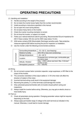
Bar Code and Serial Number](https://image.slidesharecdn.com/ig5amanualv2-200106075958/85/I-g5a-manual_v2-4_-110131-11-320.jpg)
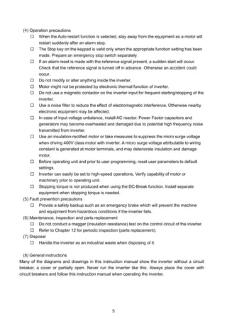
![1-2
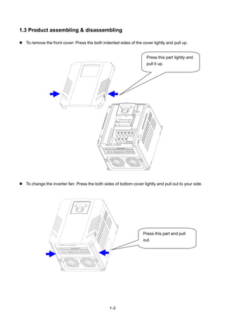
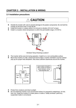
1.2 Product Details
Appearance
Inside view after front cover is removed
Refer to “1.3 To remove the front cover” for details.
Front cover:
Removed when
wiring
Bottom cover:
Removed when
wiring input power
and a motor
Status LED Display
Inverter
nameplate
4-Way button for
parameter setting
(Up/Down/Left/Right)
Control signal
Terminal
NPN, PNP
Select Switch
[ENT]
button
STOP/RESET
button
Inverter Ground
Terminal
RUN button
Power terminal
Cooling fan](https://image.slidesharecdn.com/ig5amanualv2-200106075958/85/I-g5a-manual_v2-4_-110131-12-320.jpg)

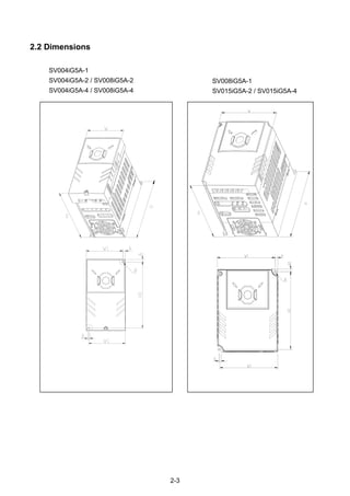
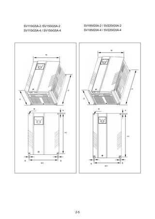
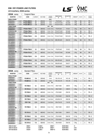
![2-6
Inverter [kW]
W
[mm]
W1
[mm]
H
[mm]
H1
[mm]
D
[mm]
Φ A
[mm]
B
[mm]
[Kg]
SV004iG5A-1 0.4 70 65.5 128 119 130 4.0 4.5 4.0 0.76
SV008iG5A-1 0.75 100 95.5 128 120 130 4.5 4.5 4.5 1.12
SV015iG5A-1 1.5 140 132 128 120.5 155 4.5 4.5 4.5 1.84
SV004iG5A-2 0.4 70 65.5 128 119 130 4.0 4.5 4.0 0.76
SV008iG5A-2 0.75 70 65.5 128 119 130 4.0 4.5 4.0 0.77
SV015iG5A-2 1.5 100 95.5 128 120 130 4.5 4.5 4.5 1.12
SV022iG5A-2 2.2 140 132 128 120.5 155 4.5 4.5 4.5 1.84
SV037iG5A-2 3.7 140 132 128 120.5 155 4.5 4.5 4.5 1.89
SV040iG5A-2 4.0 140 132 128 120.5 155 4.5 4.5 4.5 1.89
SV055iG5A-2 5.5 180 170 220 210 170 4.5 5.0 4.5 3.66
SV075iG5A-2 7.5 180 170 220 210 170 4.5 5.0 4.5 3.66
SV110iG5A-2 11.0 235 219 320 304 189.5 7.0 8.0 7.0 9.00
SV150iG5A-2 15.0 235 219 320 304 189.5 7.0 8.0 7.0 9.00
SV185iG5A-2 18.5 260 240 410 392 208.5 10.0 10.0 10.0 13.3
SV220iG5A-2 22.0 260 240 410 392 208.5 10.0 10.0 10.0 13.3
SV004iG5A-4 0.4 70 65.5 128 119 130 4.0 4.5 4.0 0.76
SV008iG5A-4 0.75 70 65.5 128 119 130 4.0 4.5 4.0 0.77
SV015iG5A-4 1.5 100 95.5 128 120 130 4.5 4.5 4.5 1.12
SV022iG5A-4 2.2 140 132 128 120.5 155 4.5 4.5 4.5 1.84
SV037iG5A-4 3.7 140 132 128 120.5 155 4.5 4.5 4.5 1.89
SV040iG5A-4 4.0 140 132 128 120.5 155 4.5 4.5 4.5 1.89
SV055iG5A-4 5.5 180 170 220 210 170 4.5 5.0 4.5 3.66
SV075iG5A-4 7.5 180 170 220 210 170 4.5 5.0 4.5 3.66
SV110iG5A-4 11.0 235 219 320 304 189.5 7.0 8.0 7.0 9.00
SV150iG5A-4 15.0 235 219 320 304 189.5 7.0 8.0 7.0 9.00
SV185iG5A-4 18.5 260 240 410 392 208.5 10.0 10.0 10.0 13.3
SV220iG5A-4 22.0 260 240 410 392 208.5 10.0 10.0 10.0 13.3](https://image.slidesharecdn.com/ig5amanualv2-200106075958/85/I-g5a-manual_v2-4_-110131-20-320.jpg)
![2-10
CAUTION
Apply the rated torque to terminal screws. Loosen screws can cause of short circuit and
malfunction. Tightening the screw too much can damage the terminals and cause short
circuit and malfunction.
Use copper wires only with 600V, 75℃ ratings for wiring.
Make sure the input power is off before wiring.
When power supply is switched off following operation, wait at least 10 minutes after LED
keypad display is off before you start working on it.
Applying input power supply to the output terminals U, V and W causes internal inverter
damage.
Use ring terminals with insulated caps when wiring the input power and motor wiring.
Do not leave wire fragments inside the inverter. Wire fragments can cause faults,
breakdowns and malfunctions.
When more than one motor is connected to one inverter, total wire length should be less
than 200m (656ft). Do not use a 3-wire cable for long distances. Due to increased leakage
capacitance between wires, over-current protective feature may operate or equipment
connected to the output side may malfunction. In case of long wire length, it should be
required to lower carrier frequency or use Micro Surge Filter.
Length between Inverter and Motor Up to 50m Up to 100m More than 100m
Allowable Carrier Frequency Less than 15kHz Less than 5kHz Less than 2.5kHz
(For products of less than 3.7kW, the wire length should be less than 100m(328ft)).
Never short B1 and B2 terminals. Shorting terminals may cause internal inverter damage.
Do not install a power factor capacitor, surge suppressor or RFI filters in the output side of
the inverter. Doing so may damage these components.
[WARNING]
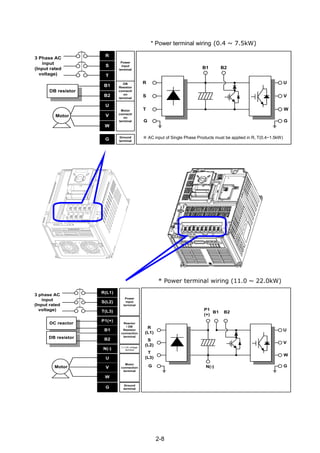
Power supply must be connected to the R, S, and T Terminals.
Connecting it to the U, V, W terminals causes internal damages to the inverter. Arranging the
phase sequence is not necessary.
Motor should be connected to the U, V, and W Terminals.
If the forward command (FX) is on, the motor should rotate counter clockwise when viewed from
the load side of the motor. If the motor rotates in the reverse, switch the U and V terminals.](https://image.slidesharecdn.com/ig5amanualv2-200106075958/85/I-g5a-manual_v2-4_-110131-24-320.jpg)
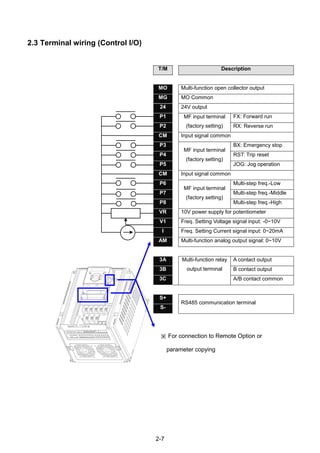
![2-12
2.5 Control terminal specification
T/M Terminal Description
Wire size[mm
2
]
Screw
size
Torque
[Nm]
Specificationsingle
wire
Stranded
P1~P8 Multi-function input T/M 1-8 1.0 1.5 M2.6 0.4
CM Common Terminal 1.0 1.5 M2.6 0.4
VR Power supply for external
potentiometer
1.0 1.5 M2.6 0.4 Output voltage: 12V
Max output current:
100mA
Potentiometer:1 ~ 5kohm
V1 Input terminal for Voltage
operation
1.0 1.5 M2.6 0.4 Max input voltage:
-10V ~ +10V input
I Input terminal for Current
operation
1.0 1.5 M2.6 0.4 0 ~ 20mA input
Internal resistor: 250
ohm
AM Multi-function analog output
terminal
1.0 1.5 M2.6 0.4 Max output voltage: 11[V]
Max output current:
10mA
MO Multi-function terminal for
open collector
1.0 1.5 M2.6 0.4 Below DC 26V,100mA
MG Ground terminal for
external power supply
1.0 1.5 M2.6 0.4
24 24V External Power Supply 1.0 1.5 M2.6 0.4 Max output current:
100mA
3A Multi-function relay output A
contact
1.0 1.5 M2.6 0.4 Below AC 250V, 1A
3B Multi-function relay output
B contact
1.0 1.5 M2.6 0.4 Below DC 30V, 1A
3C Common for Multi-function
relays
1.0 1.5 M2.6 0.4
Note 1) Tie the control wires more than 15cm away from the control terminals. Otherwise, it interferes
front cover reinstallation.
Note 2) Use Copper wires rated 600V, 75 ℃ and higher.
Note 3) Use the recommended tightening torque when securing terminal screws.
Note
When you use external power supply (24V) for multi-function input terminal (P1~P8), terminals will
be active above 12V level. Take caution not to drop the voltage below 12V.
3A 3B 3C P5 CM P6 P7 P8 VR V1 I AM
MO MG 24 P1 P2 CM P3 P4 S- S+](https://image.slidesharecdn.com/ig5amanualv2-200106075958/85/I-g5a-manual_v2-4_-110131-26-320.jpg)
![2-13
2.6 PNP/NPN selection and connector for communication option
2. When using external DC 24V [PNP]
1. When using DC 24V inside inverter [NPN]
SW S8
DC 24 V
P1
CM
CM
S8
NPNSW S8
R
R
R
CM
CPU
(inside inverter)
DC 24 V
P1
CM
CM
S8
DC24V
PNP
SW S8
R
R
R
CM
CPU
(inside inverter)](https://image.slidesharecdn.com/ig5amanualv2-200106075958/85/I-g5a-manual_v2-4_-110131-27-320.jpg)

![3-3
3.3 Recommendable Fuse, Reactors
Inverter Capacity
AC Input fuse [External Fuse]
AC Reactor DC Reactor
Current Voltage
004iG5A-1 10 A 600 V 4.20 mH, 3.5A -
008iG5A-1 10 A 600 V 2.13 mH, 5.7A -
015iG5A-1 15 A 600 V 1.20 mH, 10A
004iG5A-2 10 A 600 V 4.20 mH, 3.5A
008iG5A-2 10 A 600 V 2.13 mH, 5.7A
015iG5A-2 15 A 600 V 1.20 mH, 10A -
022iG5A-2 25 A 600 V 0.88 mH, 14A -
037iG5A-2 30 A 600 V 0.56 mH, 20A -
040iG5A-2 30 A 600 V 0.56 mH, 20A -
055iG5A-2 30 A 600 V 0.39 mH, 30A -
075iG5A-2 50 A 600 V 0.28 mH, 40A -
110iG5A-2 70 A 600 V 0.20 mH, 59 A 0.74 mH, 56 A
150iG5A-2 100 A 600 V 0.15 mH, 75 A 0.57 mH, 71 A
185iG5A-2 100 A 600 V 0.12 mH, 96 A 0.49 mH, 91 A
220iG5A-2 125 A 600 V 0.10 mH, 112 A 0.42mH, 107 A
004iG5A-4 5 A 600 V 18.0 mH, 1.3A -
008iG5A-4 10 A 600 V 8.63 mH, 2.8A -
015iG5A-4 10 A 600 V 4.81 mH, 4.8A -
022iG5A-4 10 A 600 V 3.23 mH, 7.5A -
037iG5A-4 20 A 600 V 2.34 mH, 10A -
040iG5A-4 20 A 600 V 2.34 mH, 10A -
055iG5A-4 20 A 600 V 1.22 mH, 15A -
075iG5A-4 30 A 600 V 1.14 mH, 20A -
110iG5A-4 35 A 600 V 0.81 mH, 30 A 2.76 mH, 29 A
150iG5A-4 45 A 600 V 0.61 mH, 38 A 2.18 mH, 36 A
185iG5A-4 60 A 600 V 0.45 mH, 50 A 1.79 mH, 48 A
220iG5A-4 70 A 600 V 0.39 mH, 58 A 1.54 mH, 55 A
Short Circuit Rating
“Suitable For Use ON A Circuit Capable Of Delivering Not More Than 65KA
Symmetrical Amperes. 240V drives or 480V drives Volts Maximum,”
Short Circuit FUSE/BREAKER Marking
Use Class H or RK5 UL Listed Input Fuse and UL Listed Breaker Only. See the table above
For the Voltage and Current rating of the fuse and the breaker](https://image.slidesharecdn.com/ig5amanualv2-200106075958/85/I-g5a-manual_v2-4_-110131-31-320.jpg)
![4-4
CHAPTER 4 - PROGRAMMING KEYPAD & BASIC OPERATION
4.1 Keypad features
Display
FWD Lit during forward run Blinks when a fault occurs
REV Lit during reverse run
RUN Lit during Operation
SET Lit during parameter setting
7 segment Displays operation status and parameter information
Keys
RUN Run command
STOP/RESET STOP: Stop command during operation,
RESET: Reset command when fault occurs.
UP Used to scroll through codes or increase parameter value
Down Used to scroll through codes or decrease parameter value
Left Used to jump to other parameter groups or move a cursor to the left to
change the parameter value
Right Used to jump to other parameter groups or move cursor to the right to
change the parameter value
ENT Used to set the parameter value or save the changed parameter value
Display
SET/RUN LED
FWD/REV LED
7 Segment LED
Key
RUN
STOP/RESET
Up/Down
Left/Right
Enter [ENT]](https://image.slidesharecdn.com/ig5amanualv2-200106075958/85/I-g5a-manual_v2-4_-110131-32-320.jpg)
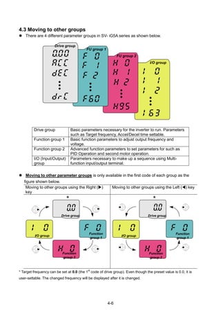
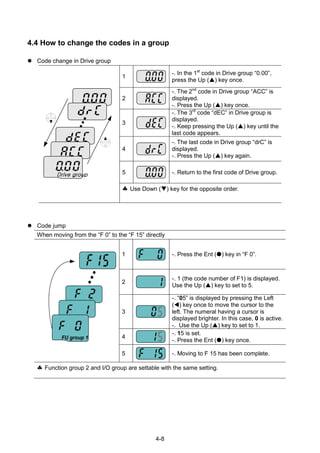
![4-9
Navigating codes in a group
When moving from F 1 to F 15 in Function group 1
1
-. In F 1, continue pressing the Up ()
key until F15 is displayed.
2 -. Moving to F15 has been complete.
The same applies to Function group 2 and I/O group.
Note: Some codes will be skipped in the middle of increment ()/decrement () for code
change. That is because it is programmed that some codes are intentionally left blank for
future use or the codes user does not use are invisible.
Refer to the Ch.5 for more specific contents
For example, when F24 [High/low frequency limit select] is set to “O (No) ”, F25 [High
frequency limit] and F26 [Low frequency limit] are not displayed during code change. But
When F24 is set to “1(Yes)”, F25 and F26 will appear on the display.](https://image.slidesharecdn.com/ig5amanualv2-200106075958/85/I-g5a-manual_v2-4_-110131-37-320.jpg)
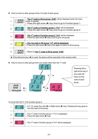
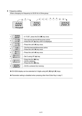
![4-10
4.5 Parameter setting
Changing parameter values in Drive Group
When changing ACC time from 5.0 sec to 16.0 sec
Drive group
1
-. In the first code “0.00”, press the Up () key once to go to the second
code.
2
-. ACC [Accel time] is displayed.
-. Press the Ent key () once.
3
-. Preset value is 5.0, and the cursor is in the digit 0.
-. Press the Left () key once to move the cursor to the left.
4 -. The digit 5 in 5.0 is active. Then press the Up () key once.
5
-. The value is increased to 6.0
-. Press the Left () key to move the cursor to the left.
6
-. 0.60 is displayed. The first 0 in 0.60 is active.
-. Press the Up () key once.
7
-. 16.0 is set.
-. Press the Ent () key once.
-. 16.0 is blinking.
-. Press the Ent () key once again to return to the parameter name.
8 -. ACC is displayed. Accel time is changed from 5.0 to 16.0 sec.
♣ In step 7, pressing the Left () or Right () key while 16.0 is blinking will disable the
setting.
Note 1) Pressing the Left ()/ Right () /Up () /Down () key while cursor is blinking will cancel
the parameter value change. Pressing the Enter key () in this status will enter the value into
memory.](https://image.slidesharecdn.com/ig5amanualv2-200106075958/85/I-g5a-manual_v2-4_-110131-38-320.jpg)
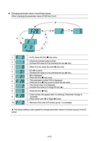
![4-13
4.6 Monitoring of operation status
Output current display
Monitoring output current in Drive group
Drive group
1
-. In [0.0], continue pressing the Up () or Down () key until [CUr] is
displayed.
2
-. Monitoring output current is provided in this parameter.
-. Press the Enter () key once to check the current.
3
-. Present output current is 5 A.
-. Press the Enter () key once to return to the parameter name.
4 -. Return to the output current monitoring code.
Other parameters in Drive group such as dCL (Inverter DC link voltage) or vOL (Inverter
output voltage) can be monitored via the same method.](https://image.slidesharecdn.com/ig5amanualv2-200106075958/85/I-g5a-manual_v2-4_-110131-41-320.jpg)


![5-1
CHAPTER 5 - FUNCTION LIST
Drive Group
LED
display
Address
for
communi
cation
Parameter
name
Min/
Max
range
Description
Factory
defaults
Adj.
during
run
Page
0.00 A100 [Frequency
command]
0 ~
400
[Hz]
This parameter sets the frequency that the
inverter is commanded to output.
During Stop: Frequency Command
During Run: Output Frequency
During Multi-step operation:
Multi-step frequency 0.
It cannot be set greater than F21- [Max
frequency].
0.00 O 7-1
ACC A101 [Accel
time]
0 ~
6000
[Sec]
During Multi-Accel/Decel operation, this
parameter serves as Accel/Decel time 0.
5.0 O 7-12
dEC A102 [Decel
time]
10.0 O 7-12
drv A103 [Drive
mode]
0 ~ 4 0 Run/Stop via Run/Stop key on the keypad 1 X 7-8
1
Terminal
operation
FX: Motor forward run
RX: Motor reverse run
7-8
2
FX: Run/Stop enable
RX: Reverse rotation select
3 RS485 communication 7-9
4 Set to Field Bus communication
1) -
Frq A104 [Frequency
setting
method]
0 ~ 9 0 Digital Keypad setting 1 0 X 7-1
1 Keypad setting 2 7-1
2
Analog
V1 1: -10 ~ +10 [V] 7-2
3 V1 2: 0 ~ +10 [V] 7-3
4 Terminal I: 0 ~ 20 [mA] 7-4
5
Terminal V1 setting 1 +
Terminal I
7-5
6
Terminal V1 setting 2+
Terminal I
7-6
7 RS485 communication 7-5
8 Digital Volume 7-6
9 Set to Field Bus communication
1) -
St1 A105 [Multi-Step
frequency
1]
0 ~
400
[Hz]
Sets Multi-Step frequency 1 during Multi-step
operation.
10.00 O 7-7
St2 A106 [Multi-Step
frequency
2]
Sets Multi-Step frequency 2 during Multi-step
operation.
20.00 O 7-7
St3 A107 [Multi-Step
frequency
3]
Sets Multi-Step frequency 3 during Multi-step
operation.
30.00 O 7-7
CUr A108 [Output
current]
Displays the output current to the motor. - - 9-1
rPM A109 [Motor
RPM]
Displays the number of Motor RPM. - - 9-1
dCL A10A [Inverter
DC link
voltage]
Displays DC link voltage inside the inverter. - - 9-1
1)
: This function can be available with iG5A Communication Option Module.](https://image.slidesharecdn.com/ig5amanualv2-200106075958/85/I-g5a-manual_v2-4_-110131-49-320.jpg)
![5-2
Drive Group
LED
display
Address
for
communi
cation
Parameter
name
Min/
Max
range
Description
Factory
defaults
Adj.
during
run
Page
vOL A10B [User
display
select]
This parameter displays the item selected at
H73- [Monitoring item select].
vOL - 9-2
vOL Output voltage
POr Output power
tOr Torque
nOn A10C [Fault
Display]
Displays the types of faults, frequency and
operating status at the time of the fault
- - 9-4
drC A10D [Direction
of motor
rotation
select]
F, r Sets the direction of motor rotation when drv -
[Drive mode] is set to either 0 or 1.
F O 7-8
F Forward
r Reverse
drv2 A10E [Drive
mode 2]
0 ~ 4 0 Run/Stop via Run/Stop key on the keypad 1 X 8-24
1
Terminal
operation
FX: Motor forward run
RX: Motor reverse run
2
FX: Run/Stop enable
RX: Reverse rotation select
3 RS-485 communication
4 Set to Filed Bus Communication
3)
Frq2
1)
A10F [Frequency
setting
method 2]
0 ~ 9 0 Digital Keypad setting 1 0 X 8-24
1 Keypad setting 2
2 Analog V1 1: -10 ~ +10 [V]
3 V1 2: 0 ~ +10 [V]
4 Terminal I: 0 ~ 20 [mA]
5
Terminal V1 setting 1 +
Terminal I
6
Terminal V1 setting 2+
Terminal I
7 RS485 communication
8 Digital Volume
9 Set to Filed Bus Communication
3)
rEF
2)
A110 PID control
standard
value
setting
0~400
[Hz] or
0~100
[%]
If H58 is 0, it is expressed as a [Hz] unit.
If H58 is 1, it is expressed as a [%] unit.
In [Hz] unit, you can‟t set Max. frequency
more than (F21).
In [%] unit, 100% means Max. frequency.
0.00 0 8-11
Fbk
2)
A111 PID control
feedback
amount
It indicates a feedback amount in PID
control.
If H58 is 0, it is expressed as a [Hz] unit.
If H58 is 1, it is expressed as a [%] unit.
- - 8-11
1)
: Only displayed when one of the Multi-function input terminals 1-8 [I17~I24] is set to “22”.
2)
: It is indicated when H49(PID control selection) is 1.
3)
: This function can be available with iG5A Communication Option Module.](https://image.slidesharecdn.com/ig5amanualv2-200106075958/85/I-g5a-manual_v2-4_-110131-50-320.jpg)
![5-3
Function group 1
LED
display
Address
for
communi
cation
Paramet
er name
Min/Max
range
Description
Factory
defaults
Adj.
during
run
Page
F 0 A200 [Jump
code]
0 ~ 71 Sets the parameter code number to jump. 1 O 4-5
F 1
A201
[Forwar
d/
Reverse
run
disable]
0 ~ 2 0 Fwd and rev run enable 0 X 7-10
1 Forward run disable
2 Reverse run disable
F 2 A202 [Accel
pattern]
0 ~ 1
0 Linear
0 X 7-15
F 3 A203 [Decel
pattern]
1 S-curve
F 4 A204 [Stop
mode
select]
0 ~ 3 0 Decelerate to stop 0 X 7-20
1 DC brake to stop
2 Free run to stop
3 Power Braking stop 8-26
F 8
1)
A208 [DC
Brake
start
frequen
cy]
0.1 ~ 60
[Hz]
This parameter sets DC brake start
frequency.
It cannot be set below F23 - [Start
frequency].
5.00 X 8-1
F 9 A209 [DC
Brake
wait
time]
0 ~ 60
[sec]
When DC brake frequency is reached,
the inverter holds the output for the
setting time before starting DC brake.
0.1 X
F10 A20A [DC
Brake
voltage]
0 ~ 200
[%]
This parameter sets the amount of DC
voltage applied to a motor.
It is set in percent of H33 – [Motor rated
current].
50 X
F11 A20B [DC
Brake
time]
0 ~ 60
[sec]
This parameter sets the time taken to
apply DC current to a motor while motor
is at a stop.
1.0 X
F12 A20C [DC
Brake
start
voltage]
0 ~ 200
[%]
This parameter sets the amount of DC
voltage before a motor starts to run.
It is set in percent of H33 – [Motor rated
current].
50 X 8-2
F13 A20D [DC
Brake
start
time]
0 ~ 60
[sec]
DC voltage is applied to the motor for DC
Brake start time before motor
accelerates.
0 X
F14 A20E [Time
for
magneti
zing a
motor]
0 ~ 60
[sec]
This parameter applies the current to a
motor for the set time before motor
accelerates during Sensorless vector
control.
0.1 X 8-15
F20 A214 [Jog
frequen
cy]
0 ~ 400
[Hz]
This parameter sets the frequency for
Jog operation.
It cannot be set above F21 – [Max
frequency].
10.00 O 8-3
1)
: Only displayed when F 4 is set to 1 (DC brake to stop).](https://image.slidesharecdn.com/ig5amanualv2-200106075958/85/I-g5a-manual_v2-4_-110131-51-320.jpg)
![5-4
Function group 1
LED
display
Address
for
communi
cation
Paramete
r name
Min/Max
range
Description
Factory
defaults
Adj.
during
run
Page
F21
1)
A215 [Max
frequency
]
40 ~ 400
[Hz]
This parameter sets the highest frequency
the inverter can output.
It is frequency reference for Accel/Decel
(See H70)
60.00 X 7-21
Caution
Any frequency cannot be set above Max
frequency except Base frequency
F22 A216 [Base
frequency
]
30 ~ 400
[Hz]
The inverter outputs its rated voltage to the
motor at this frequency (see motor
nameplate).
60.00 X 7-17
F23 A217 [Start
frequency
]
0.1 ~ 10
[Hz]
The inverter starts to output its voltage at
this frequency.
It is the frequency low limit.
0.50 X 7-21
F24 A218 [Frequen
cy
high/low
limit
select]
0 ~ 1 This parameter sets high and low limit of
run frequency.
0 X 7-21
F25
2)
A219 [Frequen
cy high
limit]
0 ~ 400
[Hz]
This parameter sets high limit of the run
frequency.
It cannot be set above F21 – [Max
frequency].
60.00 X
F26 A21A [Frequen
cy low
limit]
0 ~ 400
[Hz]
This parameter sets low limit of the run
frequency.
It cannot be set above F25 - [Frequency
high limit] and below F23 – [Start
frequency].
0.50 X
F27 A21B [Torque
Boost
select]
0 ~ 1 0 Manual torque boost 0 X 7-19
1 Auto torque boost
F28 A21C [Torque
boost in
forward
direction]
0 ~ 15
[%]
This parameter sets the amount of torque
boost applied to a motor during forward
run.
It is set in percent of Max output voltage.
2 X 7-19
F29 A21D [Torque
boost in
reverse
direction]
This parameter sets the amount of torque
boost applied to a motor during reverse
run.
It is set as a percent of Max output voltage
2 X 7-19
1)
: If H40 is set to 3 (Sensorless vector), Max. frequency is settable up to 300Hz.
2)
: Only displayed when F24 (Frequency high/low limit select) is set to 1.](https://image.slidesharecdn.com/ig5amanualv2-200106075958/85/I-g5a-manual_v2-4_-110131-52-320.jpg)
![5-5
Function group 1
LED
display
Address
for
commu
nication
Parameter
name
Min/Max
range
Description
Factory
defaults
Adj.
during
run
Page
F30 A21E [V/F
pattern]
0 ~ 2 0 {Linear} 0 X 7-17
1 {Square} 7-17
2 {User V/F} 7-18
F31
1)
A21F [User V/F
frequency
1]
0 ~ 400
[Hz]
It is used only when V/F pattern is set to
2(User V/F)
It cannot be set above F21 – [Max
frequency].
The value of voltage is set in percent of
H70 – [Motor rated voltage].
The values of the lower-numbered
parameters cannot be set above those of
higher-numbered.
15.00 X 7-18
F32 A220 [User V/F
voltage 1]
0 ~ 100
[%]
25 X
F33 A221 [User V/F
frequency
2]
0 ~ 400
[Hz]
30.00 X
F34 A222 [User V/F
voltage 2]
0 ~ 100
[%]
50 X
F35 A223 [User V/F
frequency
3]
0 ~ 400
[Hz]
45.00 X
F36 A224 [User V/F
voltage 3]
0 ~ 100
[%]
75 X
F37 A225 [User V/F
frequency
4]
0 ~ 400
[Hz]
60.00 X
F38 A226 [User V/F
voltage 4]
0 ~ 100
[%]
100 X
F39 A227 [Output
voltage
adjustment
]
40 ~ 110
[%]
This parameter adjusts the amount of
output voltage.
The set value is the percentage of input
voltage.
100 X 7-18
F40 A228 [Energy-
saving
level]
0 ~ 30
[%]
This parameter decreases output voltage
according to load status.
0 0 8-17
F50 A232 [Electronic
thermal
select]
0 ~ 1 This parameter is activated when the
motor is overheated (time-inverse).
0 0 10-1
1)
: Set F30 to 2(User V/F) to display this parameter.](https://image.slidesharecdn.com/ig5amanualv2-200106075958/85/I-g5a-manual_v2-4_-110131-53-320.jpg)
![5-6
Function group 1
LED
display
Address
for
commu
nication
Parameter
name
Min/Max
range
Description
Factory
defaults
Adj.
during
run
Page
F51
1)
A233 [Electronic
thermal
level for 1
minute]
50 ~ 200
[%]
This parameter sets max current capable of
flowing to the motor continuously for 1 minute.
The set value is the percentage of H33 –
[Motor rated current].
It cannot be set below F52 –[Electronic thermal
level for continuous].
150 0 10-1
F52 A234 [Electronic
thermal
level for
continuous]
50 ~ 150
[%]
This parameter sets the amount of current to
keep the motor running continuously.
It cannot be set higher than F51 – [Electronic
thermal level for 1 minute].
100 0
F53 A235 [Motor
cooling
method]
0 ~ 1 0 Standard motor having cooling fan
directly connected to the shaft
0 0
1 A motor using a separate motor to
power a cooling fan.
F54 A236 [Overload
warning
level]
30 ~ 150
[%]
This parameter sets the amount of current to
issue an alarm signal at a relay or multi-
function output terminal (see I54, I55).
The set value is the percentage of H33- [Motor
rated current].
150 0 10-2
F55 A237 [Overload
warning
time]
0 ~ 30 [Sec] This parameter issues an alarm signal when
the current greater than F54- [Overload
warning level] flows to the motor for F55-
[Overload warning time].
10 0
F56 A238 [Overload
trip select]
0 ~ 1 This parameter turns off the inverter output
when motor is overloaded.
1 0 10-2
F57 A239 [Overload
trip level]
30 ~ 200
[%]
This parameter sets the amount of overload
current.
The value is the percentage of H33- [Motor
rated current].
180 0
F58 A23A [Overload
trip time]
0 ~ 60 [Sec] This parameter turns off the inverter output
when the F57- [Overload trip level] of current
flows to the motor for F58- [Overload trip time].
60 0
1)
: Set F50 to 1 to display this parameter.](https://image.slidesharecdn.com/ig5amanualv2-200106075958/85/I-g5a-manual_v2-4_-110131-54-320.jpg)
![5-7
Function group 1
LED
display
Address
for
commun
ication
Paramete
r name
Min/Max
range
Description
Factory
defaults
Adj.
during
run
Page
F59 A23B [Stall
preventio
n select]
0 ~ 7 This parameter stops accelerating during
acceleration, decelerating during constant
speed run and stops decelerating during
deceleration.
0 X 10-3
During
Decel
During
constant
run
During Accel
Bit 2 Bit 1 Bit 0
0 - - -
1 - -
2 - -
3 -
4 - -
5 -
6 -
7
F60 A23C [Stall
preventio
n level]
30 ~
200
[%]
This parameter sets the amount of current to
activate stall prevention function during Accel,
Constant or Decel run.
The set value is the percentage of the H33-
[Motor rated current].
150 X 10-3
F61
1)
A23D [When
Stall
preventio
n during
decelerati
on,
voltage
limit
select
0~1 In Stall prevention run during deceleration, if
you want to limit output voltage, select 1
0 X 8-26
F63 A23F [Save
up/down
frequency
select]
0 ~ 1 This parameter decides whether to save the
specified frequency during up/down
operation.
When 1 is selected, the up/down frequency is
saved in F64.
0 X 8-4
F64
2)
A240 [Save
up/down
frequency
]
If „Save up/down frequency‟ is selected at
F63, this parameter saves the frequency
before the inverter stops or decelerated.
0.00 X 8-4
F65 A241 [Up-down
mode
select]
0~2 We can select up-down mode among three
thing
0 X 8-5
0 Increases goal frequency as a
standard of Max. frequency/Min.
frequency
1 Increases as many as step
frequency according to edge input
2 Available to combine 1 and 2
1)
: It is indicated when setting bit 2 of F59 as 1
2)
: Set F63 to 1 to display this parameter.](https://image.slidesharecdn.com/ig5amanualv2-200106075958/85/I-g5a-manual_v2-4_-110131-55-320.jpg)
![5-8
Function group 1
LED
display
Address
for
commun
ication
Parameter
name
Min/Max
range
Description
Factory
defaults
Adj.
during
run
Page
F66 A242 [Up-down
step
frequency]
0~400
[Hz]
In case of choosing F65 as a 1 or 2, it means
increase or decrease of frequency according
to up-down input
0.00 X 8-5
F70 A246 [Draw run
mode
select]
0~3 0 Inverter doesn‟t run as a draw
mode
0 X 8-28
1 V1(0~10V) input draw run
2 I(0~20mA) input draw run
3 V1(-10~10V) input draw run
F71 A247 [Draw rate] 0~100
[%]
Sets rate of draw 0.00 0 8-28](https://image.slidesharecdn.com/ig5amanualv2-200106075958/85/I-g5a-manual_v2-4_-110131-56-320.jpg)
![5-9
Function group 2
LED
display
Address
for
commu
nication
Parameter
name
Min/Max
range
Description
Factory
defaults
Adj.
during
run
Page
H 0 A300 [Jump
code]
0~95 Sets the code number to jump. 1
O
4-5
H 1 A301 [Fault
history 1]
- Stores information on the types of faults,
the frequency, the current and the
Accel/Decel condition at the time of fault.
The latest fault is automatically stored in
the H 1- [Fault history 1].
nOn
-
9-4
H 2 A302 [Fault
history 2]
- nOn
-
H 3 A303 [Fault
history 3]
- nOn
-
H 4 A304 [Fault
history 4]
- nOn
-
H 5 A305 [Fault
history 5]
- nOn
-
H 6 A306 [Reset
fault
history]
0~1 Clears the fault history saved in H 1-5. 0
O
H 7 A307 [Dwell
frequency]
0.1~400
[Hz]
When run frequency is issued, motor
starts to accelerate after dwell frequency
is applied to the motor during H8- [Dwell
time].
[Dwell frequency] can be set within the
range of F21- [Max frequency] and F23-
[Start frequency].
5.00 X 8-7
H 8 A308 [Dwell
time]
0~10
[sec]
Sets the time for dwell operation. 0.0 X
H10 A30A [Skip
frequency
select]
0 ~ 1 Sets the frequency range to skip to
prevent undesirable resonance and
vibration on the structure of the machine.
0 X 7-22
H11
1)
A30B [Skip
frequency
low limit 1]
0.1~400
[Hz]
Run frequency cannot be set within the
range of H11 thru H16. The frequency
values of the low numbered parameters
cannot be set above those of the high
numbered ones. Settable within the
range of F21 and F23.
10.00 X
H12 A30C [Skip
frequency
high limit
1]
15.00 X
H13 A30D [Skip
frequency
low limit 2]
20.00 X
H14 A30E [Skip
frequency
high limit
2]
25.00 X
H15 A30F [Skip
frequency
low limit 3]
30.00 X
H16 A310 [Skip
frequency
high limit
3]
35.00 X
1)
: only displayed when H10 is set to 1. # H17, H18 are used when F2, F3 are set to 1 (S-curve).](https://image.slidesharecdn.com/ig5amanualv2-200106075958/85/I-g5a-manual_v2-4_-110131-57-320.jpg)
![5-10
Function group 2
LED
display
Address for
communication
Parameter
name
Min/Max
range
Description
Factory
defaults
Adj.
during
run
Page
H17 A311 [S-Curve
accel/decel
start side]
1~100
[%]
Set the speed reference value to form a
curve at the start during accel/decel. If it is
set higher, linear zone gets smaller.
40 X 7-15
H18 A312 [S-Curve
accel/decel
end side]
1~100
[%]
Set the speed reference value to form a
curve at the end during accel/decel. If it is set
higher, linear zone gets smaller.
40 X
H19 A313 [Input/output
phase loss
protection
select]
0 ~ 3 0 Disabled 1 Output phase
protection
0 O 10-4
2 Input
phase
protection
3 Input/output phase
protection
H20 A314 [Power On
Start select]
0 ~ 1 This parameter is activated when drv is set to
1 or 2 (Run/Stop via Control terminal).
Motor starts acceleration after AC power is
applied while FX or RX terminal is ON.
0 O 7-11
H21 A315 [Restart
after fault
reset
selection]
0 ~1 This parameter is activated when drv is set to
1 or 2 (Run/Stop via Control terminal).
Motor accelerates after the fault condition is
reset while the FX or RX terminal is ON.
0 O 7-11
H22
1)
A316 [Speed
Search
Select]
0 ~ 15 This parameter is active to prevent any
possible fault when the inverter outputs its
voltage to the running motor.
0 X 8-17
1. H20-
[Power
On start]
2.
Restar
t after
instant
power
failure
3.
Operatio
n after
fault
4.
Normal
accel
Bit 3 Bit 2 Bit 1 Bit 0
0 - - - -
1 - - -
2 - - -
3 - -
4 - - -
1)
Normal acceleration has first priority. Even though #4 is selected along with other bits, Inverter performs Speed search
#4.](https://image.slidesharecdn.com/ig5amanualv2-200106075958/85/I-g5a-manual_v2-4_-110131-58-320.jpg)
![5-11
Function group 2
LED
display
Address
for
communic
ation
Paramete
r name
Min/Max
range
Description
Factor
y
default
s
Adj.
during
run
Page
H22
1)
A316 1. H20-
[Power
On
start]
2.
Restart
after
instant
power
failure
3.
Operati
on after
fault
4.
Nor
mal
accel
O 8-17
Bit 3 Bit 2 Bit 1 Bit 0
5 - -
6 - -
7 -
8 - - -
9 - -
10 - -
11 -
12 - -
13 -
14 -
15
H23 A317 [Current
level
during
Speed
search]
80~200
[%]
This parameter limits the amount of current
during speed search.
The set value is the percentage of the H33-
[Motor rated current].
100 O 8-17
H24 A318 [P gain
during
Speed
search]
0~9999 It is the Proportional gain used for Speed
Search PI controller.
100 O
H25 A319 [I gain
during
speed
search]
0~9999 It is the Integral gain used for Speed search
PI controller.
200 O
H26 A31A [Number
of Auto
Restart
try]
0 ~10 This parameter sets the number of restart
tries after a fault occurs.
Auto Restart is deactivated if the fault
outnumbers the restart tries.
This function is active when [drv] is set to 1 or
2 {Run/Stop via control terminal}.
Deactivated during active protection function
(OHT, LVT, EXT, HWT etc.).
0 O 8-20](https://image.slidesharecdn.com/ig5amanualv2-200106075958/85/I-g5a-manual_v2-4_-110131-59-320.jpg)
![5-12
Function group 2
LED
display
Address
for
communi
cation
Parameter
name
Min/Max
range
Description
Factory
defaults
Adj.
during run
Page
H27 A31B [Auto Restart
time]
0~60 [sec] This parameter sets the time
between restart tries.
1.0 O 8-20
H30 A31E [Motor type
select]
0.2~ 22.0 0.2 0.2kW 7.5
1)
X 8-16
~ ~
22.0 22.0kW
H31 A31F [Number of
motor poles]
2 ~ 12 This setting is displayed via rPM
in drive group.
4 X
H32 A320 [Rated slip
frequency]
0 ~ 10
[Hz]
120
Prpm
ff rs
Where, sf = Rated slip frequency
rf = Rated frequency
rpm= Motor nameplate
RPM
P = Number of Motor
poles
2.33
2)
X
H33 A321 [Motor rated
current]
0.5~150
[A]
Enter motor rated current on the
nameplate.
26.3 X
H34 A322 [No Load
Motor Current]
0.1~ 100 [A] Enter the current value detected
when the motor is rotating in rated
rpm after the load connected to
the motor shaft is removed.
Enter the 50% of the rated current
value when it is difficult to
measure H34 – [No Load Motor
Current].
11 X
H36 A324 [Motor
efficiency]
50~100
[%]
Enter the motor efficiency (see
motor nameplate).
87 X
H37 A325 [Load inertia
rate]
0 ~ 2 Select one of the following
according to motor inertia.
0 X 8-1
0 Less than 10 times
1 About 10 times
2 More than 10 times
1)
: H30 is preset based on inverter rating.
2)
: H32 ~ H36 factory default values are set based on OTIS-LG motor.](https://image.slidesharecdn.com/ig5amanualv2-200106075958/85/I-g5a-manual_v2-4_-110131-60-320.jpg)
![5-13
Function group 2
LED
display
Address
for
communi
cation
Paramet
er name
Min/Max
range
Description
Factory
defaults
Adj.
during
run
Page
H39 A327 [Carrier
frequen
cy
select]
1 ~ 15
[kHz]
This parameter affects the audible sound
of the motor, noise emission from the
inverter, inverter temp, and leakage
current. If the set value is higher, the
inverter sound is quieter but the noise
from the inverter and leakage current will
become greater.
3 O 8-21
H40 A328 [Control
mode
select]
0 ~ 3 0 {Volts/frequency Control} 0 X 7-17
1 {Slip compensation control} 8-8
3 {Sensorless vector control} 8-15
H41 A329 [Auto
tuning]
0 ~ 1 If this parameter is set to 1, it
automatically measures parameters of
the H42 and H44.
0 X 8-14
H42 A32A [Stator
resistan
ce (Rs)]
0 ~ 28
[]
This is the value of the motor stator
resistance.
- X
H44 A32C [Leakage
inductanc
e (L)]
0~ 300.0
[mH]
This is leakage inductance of the stator
and rotor of the motor.
- X
H45
1)
A32D [Sensorl
ess P
gain]
0~ 32767 P gain for Sensorless control 1000 O
H46 A32E [Sensorl
ess I
gain]
I gain for Sensorless control 100 O
H47 A32F [Sensorl
ess
torque
limit]
100~220[
%]
Limits output torque in sensorless mode,. 180.0 X
H48 A330 PWM
mode
select
0~1 If you want to limit a inverter leakage
current, select 2 phase PWM mode.
It has more noise in comparison to
Normal PWM mode.
0 X 8-30
0 Normal PWM mode
1 2 phase PWM mode
H49 A331 PID
select
0~1 Selects whether using PID control or not 0 X 8-10
H50
2)
A332 [PID F/B
select]
0 ~ 2 0 Terminal I input (0 ~ 20 mA) 0 X 8-10
1 Terminal V1 input (0 ~ 10 V)
2 RS-485 communication feedback
H51 A333 [P gain
for PID]
0~ 999.9
[%]
This parameter sets the gains for the PID
controller.
300.0 O
H52 A334 [Integral
time for
PID
0.1~32.0
[sec]
1.0 O
H53 A335 [Differen
tial time
for PID
(Dgain)]
0 ~ 30.0
[sec]
0.0 O
H54 A336 [PID
control
mode
select]
0~1 Selects PID control mode 0 X 8-10
0 Normal PID control
1 Process PID control
1)
: Set H40 to 3 (Sensorless vector control) to display this parameter.
2)
: Set H49 to 1 (PID control) to display this parameter.](https://image.slidesharecdn.com/ig5amanualv2-200106075958/85/I-g5a-manual_v2-4_-110131-61-320.jpg)
![5-14
Function group 2
LED
display
Address
for
commu-
nication
Parameter
name
Min/Max
range
Description
Factory
defaults
Adj.
during
run
Page
H55 A337 [PID output
frequency
high limit]
0.1 ~
400
[Hz]
This parameter limits the amount of the
output frequency through the PID control.
The value is settable within the range of
F21 – [Max frequency] and F23 – [Start
frequency].
60.00 O 8-10
H56 A338 [PID output
frequency
low limit]
0.1 ~
400
[Hz]
0.50 O
H57 A339 [PID
standard
value select]
0~4 Selects PID standard value.
Standard value is indicated in “rEF” of
Drive group.
0 X 8-10
0 Loader digital setting 1
1 Loader digital setting 2
2 V1 terminal setting 2: 0~10V
3 I terminal setting: 0~20mA
4 Setting as a RS-485
communication
H58 A33A PID control
unit select
0~1 Selects a unit of the standard value or
feedback amount.
0 X
0 Frequency[Hz]
1 Percentage[%]
H60 A33C [Self-
diagnostic
select]
0 ~ 3 0 Self-diagnostic disabled 0 X 8-22
1 IGBT fault/Ground fault
2 Output phase short & open/
Ground fault
3 Ground fault (This setting is
unable when more than 11kW)
H61
1)
A33D [Sleep delay
time]
0~2000
[s]
Sets a sleep delay time in PID drive. 60.0 X 8-13
H62 A33E [Sleep
frequency]
0~400
[Hz]
Sets a sleep frequency when executing a
sleep function in PID control drive.
You can‟t set more than Max.
frequency(F21)
0.00 O
H63 A33F [Wake up
level]
0~100
[%]
Sets a wake up level in PID control drive. 35.0 O
H64 A340 [KEB drive
select]
0~1 Sets KEB drive. 0 X 8-28
H65 A341 [KEB action
start level]
110~140
[%]
Sets KEB action start level according to
level.
125.0 X
H66 A342 [KEB action
stop level]
110~145
[%]
Sets KEB action stop level according to
level.
130.0 X
1):
Set H49 as a 1
2):
it is indicated when setting H64(KEB drive select) as a 1
(KEB does not operate when cut power after loading ting input (about 10%).](https://image.slidesharecdn.com/ig5amanualv2-200106075958/85/I-g5a-manual_v2-4_-110131-62-320.jpg)
![5-15
Function group 2
LED
display
Address
for
commu-
nication
Parameter
name
Min/Max
range
Description
Factory
defaults
Adj.
during
run
Page
H67 A343 [KEB action
gain]
1~2000
0
Sets KEB action gain. 1000 X 8-28
H70 A346 [Frequency
Reference
for
Accel/Decel]
0 ~ 1 0 Based on Max freq (F21) 0 X 7-12
1 Based on Delta freq.
H71 A347 [Accel/Decel
time scale]
0 ~ 2 0 Settable unit: 0.01 second. 1 O 7-13
1 Settable unit: 0.1 second.
2 Settable unit: 1 second.
H72 A348 [Power on
display]
0 ~ 17 This parameter selects the parameter to
be displayed on the keypad when the
input power is first applied.
0 O 9-2
0 Frequency command
1 Accel time
2 Decel time
3 Drive mode
4 Frequency mode
5 Multi-Step frequency 1
6 Multi-Step frequency 2
7 Multi-Step frequency 3
8 Output current
9 Motor rpm
10 Inverter DC link voltage
11 User display select (H73)
12 Fault display
13 Direction of motor rotation
select
14 Output current 2
15 Motor rpm 2
16 Inverter DC link voltage 2
17 User display select 2
H73 A349 [Monitoring
item select]
0 ~ 2 One of the following can be monitored
via vOL - [User display select].
0 O 9-2
0 Output voltage [V]
1 Output power [kW]
2 Torque [kgf m]
H74 A34A [Gain for
Motor rpm
display]
1 ~
1000
[%]
This parameter is used to change the
motor rotating speed (r/min) to
mechanical speed (m/mi) and display it.
100 O 9-1
H75 A34B [DB resistor
operating
rate limit
select]
0 ~ 1 0 Unlimited 1 O 10-8
1 Use DB resistor for the H76 set
time.](https://image.slidesharecdn.com/ig5amanualv2-200106075958/85/I-g5a-manual_v2-4_-110131-63-320.jpg)
![5-16
H76 A34C [DB resistor
operating
rate]
0 ~
30[%]
Set the percent of DB resistor operating
rate to be activated during one sequence
of operation.
10 O
H77
1)
A34D [Cooling fan
control]
0 ~ 1 0 Always ON 0 O 8-30
1 Keeps ON when its temp is
higher than inverter protection
limit temp.
Activated only during operation
when its temp is below that of
inverter protection limit.
H78 A34E [Operating
method
select when
cooling fan
malfunctions
]
0 ~ 1 0 Continuous operation when
cooling fan malfunctions.
0 O 8-31
1 Operation stopped when
cooling fan malfunctions.
H79 A34F [S/W
version]
x.xx This parameter displays the inverter
software version.
x.xx X -
H81
2)
A351 [2
nd
motor
Accel time]
0 ~
6000
[sec]
This parameter actives when the
selected terminal is ON after I17-I24 is
set to 12 {2
nd
motor select}.
5.0 O 8-21
H82 A352 [2
nd
motor
Decel time]
10.0 O
H83 A353 [2
nd
motor
base
frequency]
30 ~
400 [Hz]
60.00 X
H84 A354 [2
nd
motor
V/F pattern]
0 ~ 2 0 X
H85 A355 [2
nd
motor
forward
torque
boost]
0 ~ 15
[%]
5 X
H86 A356 [2
nd
motor
reverse
torque
boost]
5 X
H87 A357 [2
nd
motor
stall
prevention
level]
30~150
[%]
150 X 8-21
1)
Exception: Since SV004iG5A-2/SV004iG5A-4 is Natural convection type, this code is hidden.
2)
: It is indicated when choosing I17~I24 as a 12 (2
nd
motor select).
H88 A358 [2
nd
motor
Electronic
thermal
level for 1
min]
50~200
[%]
150 O
H89 A359 [2
nd
motor
Electronic
thermal
level for
continuous]
50~150
[%]
100 O
H90 A35A [2
nd
motor
rated
current]
0.1~100
[A]
26.3 X
H91
1)
A35B [Parameter
read]
0 ~ 1 Copy the parameters from inverter and
save them into remote loader.
0 X 8-32
H92 A35C [Parameter
write]
0 ~ 1 Copy the parameters from remote loader
and save them into inverter.
0 X](https://image.slidesharecdn.com/ig5amanualv2-200106075958/85/I-g5a-manual_v2-4_-110131-64-320.jpg)
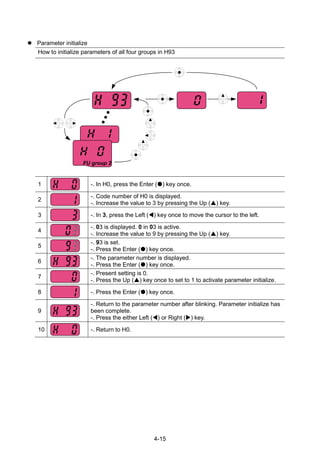
![5-17
H93 A35D [Parameter
initialize]
0 ~ 5 This parameter is used to initialize
parameters back to the factory default
value.
0 X 8-32
0 -
1 All parameter groups are
initialized to factory default
value.
2 Only Drive group is initialized.
3 Only Function group 1 is
initialized.
4 Only Function group 2 is
initialized.
5 Only I/O group is initialized.
H94 A35E [Password
register]
0 ~
FFFF
Password for H95-[Parameter lock]. Set
as Hexa value.
0 O 8-33
H95 A35F [Parameter
lock]
0 ~
FFFF
This parameter is able to lock or unlock
parameters by typing password
registered in H94.
0 O 8-33
UL (Unlock) Parameter change
enable
L (Lock) Parameter change
disable
1)
H91,H92 parameters are displayed when Remote option is installed.](https://image.slidesharecdn.com/ig5amanualv2-200106075958/85/I-g5a-manual_v2-4_-110131-65-320.jpg)
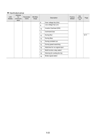
![5-18
Input/output group
LED
display
Address
for
communi
cation
Parameter
name
Min/Max
range
Description
Factory
defaults
Adj.
during
run
Page
I 0 A400 [Jump code] 0 ~ 87 Sets the code number to jump. 1 O 4-5
I 2 A402 [NV input
Min voltage]
0 ~ -10
[V]
Sets the minimum voltage of the NV (-
10V~0V) input.
0.00 O 7-2
I 3 A403 [Frequency
correspondi
ng to I 2]
0 ~ 400
[Hz]
Sets the inverter output minimum
frequency at minimum voltage of the NV
input.
0.00 O
I 4 A404 [NV input
Max
voltage]
0 ~ -10
[V]
Sets the maximum voltage of the NV
input.
10.0 O
I 5 A405 [Frequency
correspondi
ng to I 4]
0 ~ 400
[Hz]
Sets the inverter output maximum
frequency at maximum voltage of the
NV input.
60.00 O
I 6 A406 [Filter time
constant for
V1 input]
0 ~ 9999 Adjusts the responsiveness of V1 input
(0 ~ +10V).
10 O 7-2
I 7 A407 [V1 input
Min voltage]
0 ~ 10
[V]
Sets the minimum voltage of the V1
input.
0 O
I 8 A408 [Frequency
correspondi
ng to I 7]
0 ~ 400
[Hz]
Sets the inverter output minimum
frequency at minimum voltage of the V1
input.
0.00 O
I 9 A409 [V1 input
Max
voltage]
0 ~ 10
[V]
Sets the maximum voltage of the V1
input.
10 O
I10 A40A [Frequency
correspondi
ng to I 9]
0 ~ 400
[Hz]
Sets the inverter output maximum
frequency at maximum voltage of the
V1 input.
60.00 O
I11 A40B [Filter time
constant for
I input]
0 ~ 9999 Sets the input section‟s internal filter
constant for I input.
10 O 7-4
I12 A40C [I input Min
current]
0 ~ 20
[mA]
Sets the minimum current of I input. 4.00 O
I13 A40D [Frequency
correspondi
ng to I 12]
0 ~ 400
[Hz]
Sets the inverter output minimum
frequency at minimum current of I input.
0.00 O
I14 A40E [I input Max
current]
0 ~ 20
[mA]
Sets the Maximum current of I input. 20.00 O
I15 A40F [Frequency
correspondi
ng to I 14]
0 ~ 400
[Hz]
Sets the inverter output maximum
frequency at maximum current of I
input.
60.00 O 7-4
I16 A410 [Criteria for
Analog Input
Signal loss]
0 ~ 2 0: Disabled
1: activated below half of set value.
2: activated below set value.
0 O 10-7
I17 A411 [Multi-
function
input
terminal P1
define]
0 ~ 27 0 Forward run command 0 O 7-8
1 Reverse run command
I18 A412 [Multi-
function
input
terminal P2
define]
2 Emergency Stop Trip 1 O -
3 Reset when a fault occurs {RST} -](https://image.slidesharecdn.com/ig5amanualv2-200106075958/85/I-g5a-manual_v2-4_-110131-66-320.jpg)
![5-19
Input/output group
LED
display
Address
for
communi
cation
Parameter
name
Min/Max
range
Description
Factory
defaults
Adj.
during
run
Page
I19 A413 [Multi-
function
input
terminal P3
define]
4 Jog operation command 2 O 8-3
5 Multi-Step freq – Low 7-7
I20 A414 [Multi-
function
input
terminal P4
define]
6 Multi-Step freq – Mid 3 O
7 Multi-Step freq – High
I21 A415 [Multi-
function
input
terminal P5
define]
8 Multi Accel/Decel – Low 4 O 7-14
9 Multi Accel/Decel – Mid
I22 A416 [Multi-
function
input
terminal P6
define]
10 Multi Accel/Decel – High 5 O
11 DC brake during stop 8-2
I23 A417 [Multi-
function
input
terminal P7
define]
12 2nd motor select 6 O 8-21
13 -Reserved- -
I24 A418 [Multi-
function
input
terminal P8
define]
14 -Reserved- 7 O -
15 Up-
down
Frequency increase
(UP)
command
8-4
16 Frequency decrease
command (DOWN)
17 3-wire operation 8-7
18 External trip: A Contact (EtA) 10-5
19 External trip: B Contact (EtB)
20 Self-diagnostic function 8-22
21 Change from PID operation to
V/F operation
8-10
22 2
nd
Source 8-24
23 Analog Hold 7-6
24 Accel/Decel Disable 7-16
25 Up/Down Save Freq. Initialization 8-4
26 JOG-FX 8-3
27 JOG-RX
* See “Chapter 14 Troubleshooting and maintenance” for External trip A/B contact.
* Each multi-function input terminal must be set differently.](https://image.slidesharecdn.com/ig5amanualv2-200106075958/85/I-g5a-manual_v2-4_-110131-67-320.jpg)
![5-20
Input/output group
LED
display
Address
for
communic
ation
Parameter
name
Min/Max
range
Description
Factory
default
Adj.
during
run
Page
I25 A419 [Input
terminal
status
display]
BIT
7
BIT
6
BIT
5
BIT
4
BIT
3
BIT
2
BIT
1
BIT
0
- - 9-3
P8 P7 P6 P5 P4 P3 P2 P1
I26 A41A [Output
terminal
status
display]
BIT1 BIT0
- -
9-3
3AC MO
I27 A41B [Filtering
time
constant
for Multi-
function
Input
terminal]
1 ~ 15 If the value is set higher, the
responsiveness of the Input terminal is
getting slower.
4 O -
I30 A41E [Multi-
Step
frequency
4]
0 ~ 400
[Hz]
It cannot be set greater than F21 – [Max
frequency].
30.00
O
7-7
I31 A41F [Multi-
Step
frequency
5]
25.00
O
I32 A420 [Multi-
Step
frequency
6]
20.00
O
I33 A421 [Multi-
Step
frequency
7]
15.00
O
I34 A422 [Multi-
Accel time
1]
0~ 6000
[sec]
3.0 O 7-14
I35 A423 [Multi-
Decel
time 1]
3.0
I36 A424 [Multi-
Accel time
2]
4.0
I37 A425 [Multi-
Decel
time 2]
4.0
I38 A426 [Multi-
Accel time
3]
5.0
I39 A427 [Multi-
Decel
time 3]
5.0
I40 A428 [Multi-
Accel time
4]
6.0
I41 A429 [Multi-
Decel
time 4]
6.0](https://image.slidesharecdn.com/ig5amanualv2-200106075958/85/I-g5a-manual_v2-4_-110131-68-320.jpg)
![5-21
Input/output group
LED
display
Address
for
communic
ation
Parameter
name
Min/Max
range
Description
Factory
default
Adj.
during
run
Page
I42 A42A [Multi-
Accel time
5]
7.0
I43 A42B [Multi-
Decel
time 5]
7.0
I44 A42C [Multi-
Accel time
6]
8.0
I45 A42D [Multi-
Decel
time 6]
8.0
I46 A42E [Multi-
Accel time
7]
9.0
I47 A42F [Multi-
Decel
time 7]
9.0
I50 A432 [Analog
output
item
select]
0 ~ 3 Output
item
Output to 10[V] 0 O 9-6
200V 400V
0 Output
freq.
Max frequency
1 Output
current
150 %
2 Output
voltage
AC 282V AC 564V
3 Inverter
DC link
voltage
DC 400V DC 800V
I51 A433 [Analog
output
level
adjustmen
t]
10~200
[%]
Based on 10V. 100 O 9-6
I52 A434 [Frequenc
y
detection
level]
0 ~ 400
[Hz]
Used when I54 or I55 is set to 0-4.
Cannot be set higher than F21.
30.00
O
9-7
I53 A435 [Frequenc
y
detection
bandwidth
]
10.00
O
I54 A436 [Multi-
function
output
terminal
select]
0 ~ 19 0 FDT-1 12 O 9-8
1 FDT-2
2 FDT-3 9-9
3 FDT-4 17
I55 A437 [Multi-
function
relay
select]
4 FDT-5 9-10
5 Overload (OLt) 9-10
6 Inverter Overload (IOLt)
7 Motor stall (STALL)](https://image.slidesharecdn.com/ig5amanualv2-200106075958/85/I-g5a-manual_v2-4_-110131-69-320.jpg)
![5-23
Input/Output Group
LED
display
Address
for
commun
ication
Paramet
er name
Min/Max
range
Description
Factory
defaults
Adj.
during
run
Page
I56 A438 [Fault
relay
output]
0 ~ 7 When
setting the
H26–
[Number of
auto
restart try]
When the
trip other
than low
voltage trip
occurs
When the
low voltage
trip occurs
2 O 9-7
Bit 2 Bit 1 Bit 0
0 - - -
1 - -
2 - -
3 -
4 - -
5 -
6 -
7
I57 A439 [Output
terminal
select
when
commun
ication
error
occurs]
0 ~ 3 Multi-function
relay
Multi-function
output terminal
0 O 9-12
Bit 1 Bit 0
0 - -
1 -
2 -
3
I59 A43B [Commu
nication
protocol
select]
0 ~ 1 Set communication protocol. 0 X 11-2
0 Modbus RTU
1 LS BUS
I60 A43C [Inverter
number]
1 ~ 250 Set for RS485 communication 1 O 11-2
I61 A43D [Baud
rate]
0 ~ 4 Select the Baud rate of the RS485. 3 O 11-2
0 1200 [bps]
1 2400 [bps]
2 4800 [bps]
3 9600 [bps]
4 19200 [bps]
I62 A43E [Drive
mode
select
after
loss of
frequenc
y
comman
d]
0 ~ 2 It is used when freq command is given via
V1 /I terminal or RS485.
0 O 10-7
0 Continuous operation at the frequency
before its command is lost.
1 Free Run stop (Output cut-off)
2 Decel to stop
I63 A43F [Wait
time
after
loss of
frequenc
y
comman
d]
0.1 ~ 120
[sec]
This is the time inverter determines
whether there is the input frequency
command or not. If there is no frequency
command input during this time, inverter
starts operation via the mode selected at
I62.
1.0 O 10-7](https://image.slidesharecdn.com/ig5amanualv2-200106075958/85/I-g5a-manual_v2-4_-110131-71-320.jpg)
![5-24
I64 A440 [Commu
nication
time
setting]
2 ~ 100
[ms]
Frame communication time 5 O -
I65 A441 [Parity/st
op bit
setting]
0~3
When the protocol is set, the
communication format can be set.
O O -
0 Parity: None, Stop Bit: 1
1 Parity: None, Stop Bit: 2
2 Parity: Even, Stop Bit: 1
3 Parity: Odd, Stop Bit: 1
I66 A442 [Read
address
register
1]
0~42239
The user can register up to 8
discontinuous addresses and read them all
with one Read command.
5 O 11-11
I67 A443 [Read
address
register
2]
6
I68 A444 [Read
address
register
3]
7
I69 A445 [Read
address
register
4]
8
I70 A446 [Read
address
register
5]
9
I71 A447 [Read
address
register
6]
10
I72 A448 [Read
address
register
7]
11
I73 A449 [Read
address
register
8]
12
I74 A44A [Write
address
register
1]
0~42239
The user can register up to 8
discontinuous addresses and write them
all with one Write command
5 O 11-11
I75 A44B [Write
address
register
2]
6
I76 A44C [Write
address
register
3]
7
I77 A44D [Write
address
register
4]
8
I78 A44E [Write
address
register
5]
5](https://image.slidesharecdn.com/ig5amanualv2-200106075958/85/I-g5a-manual_v2-4_-110131-72-320.jpg)
![5-25
I79 A44F [Write
address
register
6]
6
I80 A450 [Write
address
register
7]
7
I81 A451 [Write
address
register
8]
8
182
1)
A452 [Brake
open
current]
0~180
[%]
Sets current level to open the brake.
It is set according to H33‟s (motor rated
current) size
50.0 O 8-26
183 A453 [Brake
open
delay
time]
0~10
[s]
Sets Brake open delay time. 1.00 X
184 A454 [Brake
open FX
frequenc
y]
0~400
[Hz]
Sets FX frequency to open the brake 1.00 X
185 A455 [Brake
open RX
frequenc
y]
0~400
[Hz]
Sets RX frequency to open the brake 1.00 X
186 A456 [Brake
close
delay
time]
0~19
[s]
Sets delay time to close the brake 1.00 X
187 A457 [Brake
close
frequenc
y
0~400
[Hz]
Sets frequency to close the brake 2.00 X
1):
It is indicated when choosing I54~I55 as a 19 (Brake signal).](https://image.slidesharecdn.com/ig5amanualv2-200106075958/85/I-g5a-manual_v2-4_-110131-73-320.jpg)

![6-3
1stFreq.
Select
DigitalVolume
Communication
Mult-step
Freq.
2ndFreq.
Select
Mult-stepFreq.
Select
Mult-step
OperationSelect
Digital
InputFilterP1
P2
P3
P4
P5
P6
P7
P8
I/OGroup
I1,6,11
Analog
InputFilter
I/OGroup
I2~I15
Analog
InputScale
V1_2
0~+10[V]
V1_1
-10~+10[V]
I
0~20[mA]
Keypador
RemoteKeypad
DRVGroup
Frq
012
3
4
5
6
7
8
DRVGroup
Frq
012
3
4
5
6
7
KeypadSetting2
V1_1:-10~10V
V1_2:0~10V
I:0~20mA
V1_1+I
V1_2+I
1
2
3
4
5
6
7
KeypadSetting10
Communication
8Up-DownOperation
8
1stReferenceFreq.
2ndReferenceFreq.
Communication
V1_2
0~+10[V]
V1_1
-10~+10[V]
I
0~20[mA]
Keypador
RemoteKeypad
KeypadSetting2
V1_1:-10~10V
V1_2:0~10V
I:0~20mA
V1_1+I
V1_2+I
1
2
3
4
5
6
7
KeypadSetting10
Communication
I/OGroup
I1,6,11
I/OGroup
I2~I15
Analog
InputFilter
Analog
InputScale
I27
I/OGroup
I17~I24
5,6,7
I/OGroup
St1
I30
I31
I32
I33
DRVGroup
St2
St3
I/OGroup](https://image.slidesharecdn.com/ig5amanualv2-200106075958/85/I-g5a-manual_v2-4_-110131-77-320.jpg)

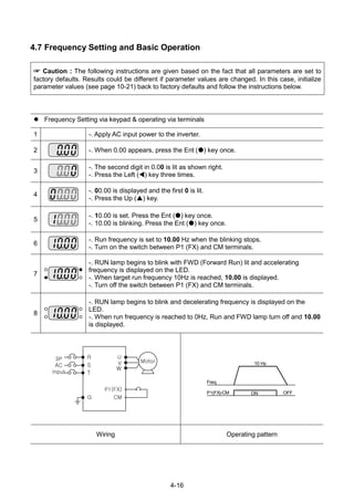
![7-1
CHAPTER 7 - BASIC FUNCTIONS
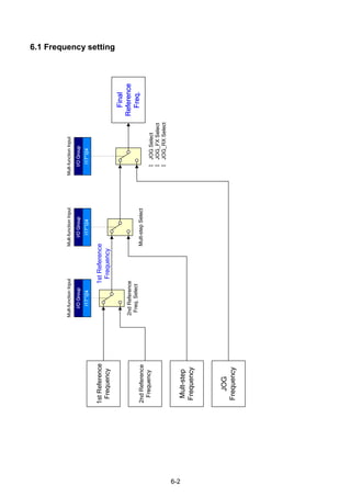
7.1 Frequency mode
Keypad Frequency setting 1
Group Code Parameter Name Setting Range Initial Unit
Drive group 0.00 [Frequency Command] - 0 ~ 400 0.00 Hz
Frq [Frequency mode] 0 0 ~ 9 0
Set Frq – [Frequency mode] to 0 {Frequency setting via Keypad 1}.
Set the desired frequency in 0.00 and press the Prog/Ent () key to enter the value into
memory.
The value is settable less than F21 – [Max frequency].
When remote keypad is connected, keypad keys on the body are deactivated.
Keypad Frequency setting 2
Group Code Parameter Name Setting Range Initial Unit
Drive group 0.00 [Frequency Command] - 0 ~ 400 0.00 Hz
Frq [Frequency mode] 1 0 ~ 9 0
Set Frq – [Frequency mode] to 1{Frequency setting via Keypad 2}.
In 0.00, frequency is changed upon pressing the Up ()/Down () key. In this case,
UP/Down keys serve as a potentiometer.
The value is settable less than F21 – [Max frequency].
When remote keypad is connected, keypad keys on the body are deactivated.](https://image.slidesharecdn.com/ig5amanualv2-200106075958/85/I-g5a-manual_v2-4_-110131-81-320.jpg)
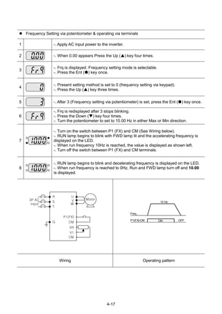
![7-2
Frequency setting via –10 ~ +10[V] input
Group Code Parameter Name Setting Range Initial Unit
Drive group 0.00 [Frequency Command] - 0 ~400 0.00 Hz
Frq [Frequency Mode] 2 0 ~ 9 0
I/O group I 2 [NV input minimum voltage] - 0 ~ -10 0.0 V
I 3 [Frequency corresponding to I2] - 0 ~ 400 0.00 Hz
I 4 [NV input max voltage] - 0 ~ 10 10.00 V
I 5 [Frequency corresponding to I4] - 0 ~ 400 60.00 Hz
I6 ~ I10 [V1 input]
Set Frq – [Frequency Mode] to 2.
The set frequency can be monitored in 0.00 - [Frequency Command].
Apply –10V ~ +10V signal between V1 and CM terminal.
Output frequency corresponding to –10V ~ +10V input voltage to V1 terminal
I 2 ~ I 5: Setting input range and corresponding frequency to -10V ~ 0V V1 input voltage
Ex) when minimum (-) input voltage is -2V with corresponding frequency 10Hz and Max
voltage is –8V with run freq. 50Hz.
V1
CM
When using -10 ~ 10V from external
circuit
-10 ~ +10 V
Output freq
(Positive)
Output freq
(Negative)
Input
voltage
0~10[V]-10~0[V]
I 2I 4
I 3
I 5
Set freq.
V1 input
-8V -2V
10Hz
50Hz](https://image.slidesharecdn.com/ig5amanualv2-200106075958/85/I-g5a-manual_v2-4_-110131-82-320.jpg)
![7-3
I6 ~ I10: Setting input range and corresponding frequency to 0 ~ +10V V1 input voltage
Ex) when minimum (+) input voltage is 2V with corresponding frequency 10Hz and Max
voltage is 8V with run freq.
Frequency setting via 0 ~ 10 [V] input or Terminal Potentiometer
Group Code Parameter Name Setting Range Initial Unit
Drive group 0.00 [Frequency Command] - 0 ~400 0.00 Hz
Frq [Frequency Mode] 3 0 ~ 9 0
I/O group I 6
[Filter time constant for V1
input]
10 0 ~ 9999 10
I 7 [V1 input Min voltage] - 0 ~ 10 0 V
I 8
[Frequency corresponding
to I 7]
- 0 ~ 400 0.00 Hz
I 9 [V1 input max voltage] - 0 ~ 10 10 V
I10
[Frequency corresponding
to I 9]
- 0 ~ 400 60.00 Hz
Select 3 in Frq code of Drive group.
0-10V can be directly applied from an external controller or a potentiometer connected on
terminals VR, V1 and CM.
Wire the terminals as shown below and refer to I 6 ~ I 10.
VR
V1
CM
Wiring of potentiometer
V1
CM
0 ~ 10V input via external controller
Set freq.
V1 input
I 7 I 9
I 8
I 10
2V 8V
10Hz
50Hz](https://image.slidesharecdn.com/ig5amanualv2-200106075958/85/I-g5a-manual_v2-4_-110131-83-320.jpg)
![7-4
Frequency setting via 0 ~ 20 [mA] input
Group Code Parameter Name Setting Range Initial Unit
Drive
group
0.00 [Frequency Command] - 0 ~400 0.00 Hz
Frq [Frequency Mode] 4 0 ~ 9 0
I/O
group
I11
[Filter time constant for I input]
10 0 ~ 9999 10
I12 [I input minimum current] - 0 ~ 20 4 mA
I13 [Frequency corresponding to I12] - 0 ~ 400 0.00 Hz
I14 [I input max current] - 0 ~ 20 20 mA
I15 [Frequency corresponding to I14] - 0 ~ 400 60.00 Hz
Select 4 in Frq code of Drive group.
Frequency is set via 0~20mA input between I and CM terminal.
Frequency setting via -10 ~ +10[V] voltage input + 0 ~ 20[mA] input
Group Code Parameter Name Setting Range Initial Unit
Drive
group
0.00 [Frequency Command] - 0 ~400 0.00 Hz
Frq [Frequency Mode] 5 0 ~ 9 0
Select 5 in Frq code of Drive group.
Override function available using Main/Auxiliary speed adjustment
Related code: I 2 ~ I 5, I 6 ~ I10, I11 ~ I15
Override function is to gain precise control and fast response by combining Main and Auxiliary
speed input. Fast response can be achieved by Main speed and precise control can be
accomplished by Aux. speed if the accuracy of Main/Aux speed is set differently.
Follow the setting below when Main speed is given via 0 ~ 20mA with Aux. speed via V1 terminal
(–10 ~ 10V).
When override function is used, select the Main/Aux. speed according to loads used.](https://image.slidesharecdn.com/ig5amanualv2-200106075958/85/I-g5a-manual_v2-4_-110131-84-320.jpg)
![7-5
Group Code Parameter Name Setting Unit
I/O group I 2 [NV input Min voltage] 0 V
I 3 [Frequency corresponding to I 2] 0.00 Hz
I 4 [NV input Max voltage] 10.00 V
I 5 [Frequency corresponding to I 4] 5.00 Hz
I7 [V1 input Min voltage] 0.00 V
I 8 [Frequency corresponding to I 7] 0.00 Hz
I 9 [V1 input max voltage] 10.00 V
I10 [Frequency corresponding to I 9] 5.00 Hz
I12 [I input minimum current] 4.00 mA
I13 [Frequency corresponding to I 12] 0.00 Hz
I14 [I input max current] 20.00 mA
I15 [Frequency corresponding to I 14] 60.00 Hz
After the above setting is made, if 5V is applied to V1 with 12mA given to terminal I, output
frequency would be 32.5Hz. If –5V is applied to V1 terminal with 12mA given to terminal I, output
frequency would be 27.5Hz.
Frequency setting via 0 ~ 10[V] + 0 ~ 20[mA] input
Group Code Parameter Name Setting Range Initial Unit
Drive
group
0.00 [Frequency Command] - 0 ~400 0.00 Hz
Frq [Frequency Mode] 6 0 ~ 9 0
Select 6 in Frq code of Drive group.
Related code: I 6 ~ I 10, I 11 ~ I 15
Refer to Frequency setting via -10 ~ +10V voltage input + 0 ~ 20mA input.
Frequency setting via RS 485 communication
Group Code Parameter Name Setting Range Initial Unit
Drive
group
0.0 [Frequency Command] - 0 ~400 0.00 Hz
Frq [Frequency Mode] 7 0 ~ 9 0
Select 7 in Frq code of Drive group.
Related code: I 59, I 60, I 61
Refer to Chapter 13. RS485 communication.](https://image.slidesharecdn.com/ig5amanualv2-200106075958/85/I-g5a-manual_v2-4_-110131-85-320.jpg)
![7-6
Frequency setting via Digital Volume (up-down)
Group Code Parameter Name Setting Range Initial Unit
Drive
group
0.0 [Frequency Command] - 0 ~400 0.00 Hz
Frq [Frequency Mode] 8 0 ~ 9 0
Select 7 in Frq code of Drive group.
Related code: I 59, I 60, I 61
Refer to Chapter 13. RS485 communication.
Analog Hold
Group Code Parameter Name Setting Range Initial Unit
Drive
group
Frq [Frequency Mode] 2 ~ 7 0 ~ 9 0
I/O group I17
[Multi-function input terminal
P1 define]
-
0 ~25
0
~ ~
I24
[Multi-function input
terminal P8 define]
23 7
It is available when Frq code setting is 2 ~ 7.
Select one terminal to use for Analog Hold command among Multi-function input terminal
(P1 ~ P8).
When P8 terminal is selected,
Frequency
P8
Operation
command
Set freq.](https://image.slidesharecdn.com/ig5amanualv2-200106075958/85/I-g5a-manual_v2-4_-110131-86-320.jpg)
![7-7
7.2 Multi-Step Frequency setting
Group Code Parameter Name Setting Range Initial Unit
Drive group 0.0 [Frequency Command] 5.0 0 ~ 400 0.00 Hz
Frq [Frequency Mode] 0 0 ~ 9 0 -
St1 [Multi-Step frequency 1] - 0 ~ 400 10.00 Hz
St2 [Multi-Step frequency 2] - 20.00
St3 [Multi-Step frequency 3] - 30.00
I/O group I22
[Multi-function input
terminal P6 define]
5
0 ~ 24
5 -
I23
[Multi-function input
terminal P7 define]
6 6 -
I24
[Multi-function input
terminal P8 define]
7 7 -
I30 [Multi-Step frequency 4] - 0 ~ 400 30.00 Hz
I31 [Multi-Step frequency 5] - 25.00
I32 [Multi-Step frequency 6] - 20.00
I33 [Multi-Step frequency 7] - 15.00
Select a terminal to give Multi-step frequency command among P1-P8 terminals.
If terminals P6-P8 are selected, set I22-I24 to 5-7 to give Multi-step frequency command.
Multi-step frequency 0 is settable in Frq – [Frequency mode] and 0.00 – [Frequency
command].
Multi-step frequency 1-3 are set at St1-St3 in Drive group, while Step frequency 4-7 are
set at I30-I33 in I/O group.
Step
freq.
FX or RX P8 P7 P6
0 - - -
1 - -
2 - -
3 -
4 - -
5 -
6 -
7
Freq.
P6
P7
P8
FX
RX
Step
0
Step
1
Step
2
Step
3
Step
4
Step
5
Step
6
Step
7
Step
0](https://image.slidesharecdn.com/ig5amanualv2-200106075958/85/I-g5a-manual_v2-4_-110131-87-320.jpg)
![7-8
7.3 Operating command setting method
Operation via keypad RUN key and STOP/RST key
Group Code Parameter Name Setting Range Initial Unit
Drive group drv [Drive mode] 0 0 ~ 4 1
drC
[Direction of motor rotation
select]
- F, r F
Set drv – [Drive mode] to 0.
Acceleration is started upon pressing the Run key while operating frequency is set. Motor
decelerates to stop by pressing the STOP/RST key.
Selecting rotation direction is available at drC - [Direction of motor rotation select] when
operating command is issued via keypad.
drC
[Direction of
motor rotation
select]
F Forward
r Reverse
When remote keypad is connected, body-embedded keypad
is deactivated.
Operating command via FX, RX terminal 1
Group Code Parameter Name Setting Range Initial Unit
Drive group drv [Drive mode] 1 0 ~ 4 1
I/O group I17
[Multi-function input
terminal P1 define]
0 0 ~ 27 0
I18
[Multi-function input
terminal P2 define]
1 0 ~ 27 1
Set drv – [Drive mode] to 1.
Set I17 and I18 to 0 and 1 to use P1 and P2 as FX and RX terminals.
“FX” is Forward run command and “RX” Reverse run.
Motor is stopped when FX/RX terminal is
ON/OFF at the same time.
Forward :
Counter-clockwise
FX
RX
Freq.](https://image.slidesharecdn.com/ig5amanualv2-200106075958/85/I-g5a-manual_v2-4_-110131-88-320.jpg)
![7-9
Operating command via FX, RX terminal 2
Group Code Parameter Name Setting Range Initial Unit
Drive group drv [Drive mode] 2 0 ~ 4 1
I/O group I17
[Multi-function input
terminal P1 define]
0 0 ~ 27 0
I18
[Multi-function input
terminal P2 define]
1 0 ~ 27 1
Set the drv to 2.
Set I17 and I18 to 0 and 1 to use P1 and P2 as FX and RX terminals.
FX: Operating command setting. Motor runs in forward direction when RX terminal (P2) is
OFF.
RX: Direction of motor rotation select. Motor runs in reverse direction when RX terminal
(P2) is ON.
Operating command via RS485 communication
Group Code Parameter Name Setting Range Initial Unit
Drive group drv [Drive mode] 3 0 ~ 4 1
I/O group I59
[Communication protocol
select]
- 0 ~ 1 0
I60 [Inverter number] - 1 ~ 250 1
I61 [Baud rate] - 0 ~ 4 3
Set the drv to 3.
Set I59, I60 and I61correctly.
Inverter operation is performed via RS485 communication.
Refer to Chapter. 13, RS485 communication.
FX
RX
Freq.](https://image.slidesharecdn.com/ig5amanualv2-200106075958/85/I-g5a-manual_v2-4_-110131-89-320.jpg)
![7-10
Rotating direction select via –10 ~ +10[V] input of V1 terminal
Group Code Parameter Name Setting Range Initial Unit
Drive group frq [Frequency setting] 2 0 ~ 8 0
drv [Drive mode] - 0 ~ 4 1
Set frq to 2.
Inverter is operating as the table below regardless of Drive mode setting.
FWD RUN Command REV RUN Command
0 ~ +10 [V] FWD RUN REV RUN
-10 ~ 0 [V] REV RUN FWD RUN
Motor runs in Forward direction when input voltage to V1-CM is 0~10[V] and FWD RUN
command is active. When input voltage polarity is reversed to –10~0[V] during FWD RUN, motor
decelerates to stop and runs in reverse direction.
When input voltage to V1-CM is 0~10[V] and REV RUN command is active, motor runs in
Reverse direction and if -10~0[V] is input, motor rotating direction is reverse.
FX/RX Run Disable
Group Code Parameter Name Setting Range Initial Unit
Drive group drC
[Direction of motor
rotation select]
- F, r F
Function group 1 F 1
[Forward/Reverse run
disable]
- 0 ~ 2 0
Select the direction of motor rotation.
0: Forward and Reverse run enable
1: Forward run disable
2: Reverse run disable](https://image.slidesharecdn.com/ig5amanualv2-200106075958/85/I-g5a-manual_v2-4_-110131-90-320.jpg)
![7-11
Power On Start select
Group Code Parameter Name Setting Range Initial Unit
Drive group drv [Drive mode] 1, 2 0 ~ 4 1
Function group 2 H20 [Power On Start select] 1 0 ~ 1 0
Set H20 to 1.
When AC input power is applied to the inverter with drv set to 1 or 2 {Run via control
terminal} ON, motor starts acceleration.
This parameter is inactive when drv is set to 0 {Run via keypad} or 3 {RS485
communication}.
CAUTION
Particular attention must be directed to this function due to potential hazard as motor starts to
run suddenly upon applying AC input power.
Run
command
Frequency
Input voltage
When H20 is 0 When H20 is 1
Restart after fault reset
Group Code Parameter Name Setting Range Initial Unit
Drive group drv [Drive mode] 1, 2 0 ~ 4 1
Function group 2 H21
[Restart after fault reset
selection]
1 0 ~ 1 0
Set H21 to 1.
Motor starts acceleration if drv is set to 1 or 2 and the selected terminal is ON when a fault
is cleared.
This parameter is inactive when drv is set to 0 {Run via keypad} or 3 {RS485
communication}.
CAUTION
Particular attention must be directed to this function due to potential hazard as motor starts to
run suddenly after the fault is cleared.](https://image.slidesharecdn.com/ig5amanualv2-200106075958/85/I-g5a-manual_v2-4_-110131-91-320.jpg)
![7-12
Run
command
Reset
Frequency
When H21 is 0 When H21 is 1
7.4 Accel/Decel time and pattern setting
Accel/Decel time setting based on Max frequency
Group Code Parameter Name Setting Range Initial Unit
Drive group ACC [Accel time] - 0 ~ 6000 5.0 Sec
dEC [Decel time] - 0 ~ 6000 10.0 Sec
Function group1 F21 [Max Frequency] - 40 ~ 400 60.00 Hz
Function group2 H70
[Frequency
Reference for
Accel/Decel]
0 0 ~ 1 0
H71
[Accel/Decel time
scale]
- 0 ~ 2 1
Set the desired Accel/Decel time at ACC/dEC in Drive group.
If H70 is set to 0 {Max frequency}, Accel/Decel time is the time that takes to reach the max
freq from 0 Hz.
Desired Accel/Decel time unit is settable at the H71.
Accel/Decel time is set based on F21 – [Max frequency]. For instance, if F21 is set to 60Hz,
Accel/Decel time 5 sec, and run frequency 30Hz, time to reach 30Hz would be 2.5 sec.
Run
command
Run Freq.
30Hz
Accel time Decel time
Max. freq.
60Hz](https://image.slidesharecdn.com/ig5amanualv2-200106075958/85/I-g5a-manual_v2-4_-110131-92-320.jpg)
![7-13
More precise time unit can be set corresponding to load characteristics as shown below.
In SV-iG5A, number display is available up to 5. Therefore, if time unit is set to 0.01 sec, Max
Accel/Decel time would be 600.00 sec.
Code Name
Set
value
Setting range Description
H71 [Accel/Decel
time scale]
0 0.01~600.00 Setting Unit: 0.01 sec
1 0.1~6000.0 Setting Unit: 0.1 sec
2 1~60000 Setting Unit: 1 sec
Accel/Decel time setting based on Operating Frequency
Group Code Parameter Name Setting Range Initial Unit
Drive group ACC [Accel time] - 0 ~ 6000 5.0 Sec
dEC [Decel time] - 0 ~ 6000 10.0 Sec
Function group 2 H70
[Frequency
Reference for
Accel/Decel]
1 0 ~ 1 0
Accel/Decel time is set at the ACC/dEC.
If you set H70 to 1 {Delta frequency}, Accel/Decel time is the time that takes to reach a
target freq from constant run freq (Current operating freq.).
When H70 and Accel time are set to 1 {Delta frequency} and 5 sec, respectively,
The below graph in Section A shows the change in operating frequency when target frequency is
set to 10Hz at first and then changed to 30Hz.
Operating
command
Operating
freq.
5 7 12
Time
[Sec]
5 sec 5 sec
10Hz
30Hz
Section A](https://image.slidesharecdn.com/ig5amanualv2-200106075958/85/I-g5a-manual_v2-4_-110131-93-320.jpg)
![7-14
Multi-Accel/Decel time setting via Multi-function terminals
Group Code Parameter Name Set Range Initial Unit
Drive
group
ACC
[Accel time]
-
0 ~
6000
5.0 Sec
dEC
[Decel time]
-
0 ~
6000
10.0 Sec
I/O
group
I17 [Multi-function input terminal P1 define] 0
0 ~ 27
0
I18 [Multi-function input terminal P12 define] 1 1
I19
[Multi-function input terminal P3
define]
8 2
I20
[Multi-function input terminal P4
define]
9 3
I21
[Multi-function input terminal P5
define]
10 4
I34 [Multi-Accel time 1] - 0 ~
6000
3.0 Sec
~ ~
I47 [Multi-Decel time 7] - 9.0
Set I19, I20, I21 to 8, 9, 10 if you want to set Multi - Accel/Decel time via P3-P5 terminals.
Multi-Accel/Decel time 0 is settable at ACC and dEC.
Multi-Accel/Decel time 1-7 is settable at I34-I47.
Accel/Decel
time
P5 P4 P3
0 - - -
1 - -
2 - -
3 -
4 - -
5 -
6 -
7
Frequency
P3
P4
P5
FX
Accel
Time 0
Accel
time 1
Accel
time 2
Accel
time 3
Decel
time 4
Decel
time 5 Decel
time 6
Decel
time 7](https://image.slidesharecdn.com/ig5amanualv2-200106075958/85/I-g5a-manual_v2-4_-110131-94-320.jpg)
![7-15
Accel/Decel pattern setting
Group Code Parameter Name Setting range Initial Unit
Function
group 1
F 2 [Accel pattern] 0 Linear
0
F 3 [Decel pattern] 1 S-curve
Function
group 2
H17
[S-Curve Accel/Decel start
side] 0~
100
40 %
H18
[S-Curve Accel/Decel end
side]
40 %
Accel/Decel pattern is settable at F2 and F3.
Linear: This is a general pattern for constant torque applications.
S-curve: This curve allows the motor to accelerate and decelerate smoothly.
CAUTION
For S-curve, the actual Accel/Decel time takes longer than the time set by user.
H17 sets the starting ratio between S-curve and Linear in 1/2 of Accel/Decel Ref. Frequency. For
smooth Accel/Decel starting, increase H17 to extend S-curve ratio.
H18 sets the ending ratio between S-curve and Linear in 1/2 of Accel/Decel Ref. Frequency. For
smooth and accurate speed arrival and stopping, increase H18 to extend S-curve ratio.
Operating
command
Freq.
Accel
time
Decel
time
Freq
H17 H17H18 H18
Accel/Decel
Ref. Freq.
Accel
Start
Accel
End
Decel
Start
Decel
End
1/2 of
Accel/Decel
Ref. Freq](https://image.slidesharecdn.com/ig5amanualv2-200106075958/85/I-g5a-manual_v2-4_-110131-95-320.jpg)
![7-16
Note that setting Frequency Ref. for Accel/decel (H70) is set to Max Freq and target freq is set
below Max freq. the shape of S-curve may be distorted.
Accel time for S-curve setting
2
18
2
17 H
ACC
H
ACCACC
Decel time for S-curve setting
2
18
2
17 H
dEC
H
dECdEC
ACC, dEC indicate the set time in Drive group.
Accel/Decel Disable
Group Code Parameter Name Setting Range Initial Unit
I/O group I17
[Multi-function input terminal
P1 define]
-
0 ~27
0
~ ~
I24
[Multi-function input
terminal P8 define]
24 7
Select one terminal among Multi-function input terminals 1-8 to define Accel/Decel disable.
If P8 is selected, set I24 to 24 to activate this function.
CAUTION
If Target Frequency is
below Max Frequency, the
waveform will be shown
with the top portion cut out.
Freq
H17 H17H18 H18
Accel/decel
Ref Freq
(H70)
Target Freq
Freq.
P8
Operating
command](https://image.slidesharecdn.com/ig5amanualv2-200106075958/85/I-g5a-manual_v2-4_-110131-96-320.jpg)
![7-17
7.5 V/F control
Linear V/F pattern operation
Group Code Parameter Name Setting Range Initial Unit
Function group 1 F22 [Base frequency] - 30 ~ 400 60.00 Hz
F23 [Start frequency] - 0.1 ~ 10.0 0.50 Hz
F30 [V/F pattern] 0 0 ~ 2 0
Function group 2 H40 [Control mode select] - 0 ~ 3 0
Set F30 to 0 {Linear}.
This pattern maintains a linear Volts/frequency ratio from F23 - [Start frequency] to F22-
[Base frequency]. This is appropriate for constant torque applications.
Base Frequency: Inverter outputs its rated voltage at this level. Enter the motor nameplate
frequency.
Start Frequency: Inverter starts to output its voltage at this level.
Square V/F pattern
Group Code Parameter Name Setting Range Initial Unit
Function
group 1
F30 [V/F pattern] 1 0 ~ 2 0
Set F30 to 1{Square}.
This pattern maintains squared volts/hertz ratio. Appropriate applications are fans, pumps,
etc.
Run
command
Freq.
Start freq.
Base freq.
Voltage
Inverter rated
voltage
Freq.
Base freq.
100%
Voltage](https://image.slidesharecdn.com/ig5amanualv2-200106075958/85/I-g5a-manual_v2-4_-110131-97-320.jpg)
![7-18
User V/F pattern operation
Group Code Parameter Name Setting Range Initial Unit
Function group 1 F30 [V/F pattern] 2 0 ~ 2 0
F31 [User V/F frequency 1] - 0 ~ 400 15.00 Hz
~ ~
F38 [User V/F voltage 4] - 0 ~ 100 100 %
Select F30 to 2 {User V/F}.
User can adjust the Volt/Frequency ratio according to V/F pattern of specialized motors
and load characteristics.
CAUTION
In case of using a standard induction motor, if this value is set much higher than linear V/F
pattern, it could result in torque shortage or motor overheating due to over-energizing.
When User V/F pattern is active, F28 - [Torque Boost in forward direction] and F29 - [Torque
Boost in reverse direction] are deactivated.
Output voltage adjustment
Group Code Parameter Name Setting Range Initial Unit
Function group 1 F39
[Output voltage
adjustment]
- 40 ~ 110 100 %
This function is used to adjust the output voltage of the inverter. This is useful when you
use a motor that has a rated voltage lower than the input voltage.
Freq.
Voltage
Start
freq.
F31 F33 F35 F37 Base
freq.
F32
F34
F36
F38
100%
Linear
V/F
Freq.
Voltage
Base freq.
100%
70%
100% setting
70% setting](https://image.slidesharecdn.com/ig5amanualv2-200106075958/85/I-g5a-manual_v2-4_-110131-98-320.jpg)
![7-19
Manual torque boost
Group Code Parameter Name Setting Range Initial Unit
Function
group 1
F27 [Torque Boost select] 0 0 ~ 1 0
F28 [Torque boost in forward direction] - 0 ~ 15 2 %
F29 [Torque boost in reverse direction]
Set F27 to 0 {Manual torque boost}.
The values of [Torque boost in forward/reverse direction] are set separately in F28 and
F29.
CAUTION
If the boost value is set much higher than required, it may cause motor overheating due to
over-energizing.
Auto torque boost
Group Code Parameter Name Setting Range Initial Unit
Function group 1 F27 [Torque Boost select] 1 0 ~ 1 0
Function group 2 H34
[No load motor
Current]
- 0.1 ~ 100 - A
H41 [Auto tuning] 0 0 ~ 1 0
H42 [Stator resistance (Rs)] - 0 ~ 28 -
Before Auto Torque Boost setting, H34 and H42 should be set correctly (See page 10-6,
10-10).
Select 1{Auto torque boost} in F27.
Inverter automatically calculates torque boost value using motor parameters and outputs
the corresponding voltage.
FX
Time
RX
Voltage
FXtorque
boost
No torque boost
100%
RXtorque
boost](https://image.slidesharecdn.com/ig5amanualv2-200106075958/85/I-g5a-manual_v2-4_-110131-99-320.jpg)
![7-20
7.6 Stop method select
Decel to stop
Group Code Parameter Name Setting Range Initial Unit
Function group 1 F4 [Stop mode select] 0 0 ~ 3 0
Select 0 {decel to stop} in F4 code.
Motor decelerates to 0 Hz and stops during the setting time.
DC braking to stop
Group Code Parameter Name Setting Range Initial Unit
Function group 1 F4 [Stop mode select] 1 0 ~ 3 0
Select 1 {DC brake to stop} in F4 code.
Refer to page 8-1.
Free run stop
Group Code Parameter Name Setting Range Initial Unit
Function group 1 F4 [Stop mode select] 2 0 ~ 3 0
Select 2 {Free run stop} in F4 code.
When operating command is turned OFF, Output Frequency and voltage are shut down.
Operating
command
Freq.
Decel
time
Operating
command
Freq, Voltage](https://image.slidesharecdn.com/ig5amanualv2-200106075958/85/I-g5a-manual_v2-4_-110131-100-320.jpg)
![7-21
7.7 Frequency limit
Frequency limit using Max Frequency and Start Frequency
Group Code Parameter Name Setting Range Initial Unit
Function
group 1
F21 [Max frequency] - 0 ~ 400 60.00 Hz
F23 [Start frequency] - 0.1 ~ 10 0.50 Hz
Max Frequency: Frequency highest limit. Any frequency cannot be set above [Max
frequency] except for F22 [Base frequency].
Start Frequency: Frequency lowest limit. If a frequency is set lower than this, 0.00 is
automatically set.
Frequency command limit using High/Low limit
Group Code Parameter Name Setting Range Initial Unit
Function
group 1
F24
[Frequency high/low
limit select]
1 0 ~ 1 0
F25 [Frequency high limit] - 0 ~ 400 60.00 Hz
F26 [Frequency low limit] - 0 ~ 400 0.50 Hz
Set F24 to 1.
Active run frequency can be set within the range of F25 and F26.
When frequency setting is done via Analog input (voltage or current input), the inverter operates
within the range of high and low limit frequency as shown below.
This setting is also valid when frequency setting is done via keypad.
Freq.
V1(Voltage input)
Max freq.
0 20mA
10V
I (Current input)
High limit
freq.
Low limit
freq.
When freq. limit is not
selected](https://image.slidesharecdn.com/ig5amanualv2-200106075958/85/I-g5a-manual_v2-4_-110131-101-320.jpg)
![7-22
Skip frequency
Group Code Parameter Name Setting Range Initial Unit
Function
group 2
H10 [Skip frequency select] 1 0 ~ 1 0
H11 [Skip frequency low limit 1] - 0.1 ~ 400 10.00 Hz
~ ~
H16 [Skip frequency low limit 3] - 0.1 ~ 400 35.00 Hz
Set H10 to 1.
Run frequency setting is not available within the skip frequency range of H11-H16.
Skip frequency is settable within the range of F21 – [Max frequency] and F23 – [Start
frequency].
When it is desired to avoid resonance attributable to the natural frequency of a mechanical
system, these parameters allow resonant frequencies to be skipped. Three different areas of
[Skip frequency High/Low limit] can be set with the skip frequencies set to either the top or bottom
point of each area. However, during acceleration or deceleration, the run frequency within the set
area is valid.
In the case of increasing frequency setting as shown above, if frequency set value (Analog
setting via voltage, current, or digital setting via keypad) is within the range of Skip frequency, it
maintains Skip freq RS485 communication, frequency low limit value. If the set value is outside
the range, it increases the frequency.
In the case of decreasing frequency setting, if frequency set value (Analog setting via voltage,
current, RS485 communication, or Digital setting via keypad) is within the range of Skip frequency,
it maintains Skip frequency high limit value. If the set value is outside the range, it decreases the
frequency.
Run
command
Freq.
H11
H12
H13
H14
H15
H16
V1(Voltage input)
0 20mA
10V
I (Current input)
Freq. Up setting
Freq. Down
setting](https://image.slidesharecdn.com/ig5amanualv2-200106075958/85/I-g5a-manual_v2-4_-110131-102-320.jpg)
![8-1
CHAPTER 8 - ADVANCED FUNCTIONS
8.1 DC brake
Stopping motor by DC brake
Group Display Parameter Name Setting Range Default Unit
Function
group 1
F 4 [Stop mode select] 1 0 ~ 3 0
F 8 [DC Brake start frequency] - 0.1 ~ 60 5.00 Hz
F 9 [DC Brake wait time] - 0 ~ 60 0.1 sec
F10 [DC Brake voltage] - 0 ~ 200 50 %
F11 [DC Brake time] - 0 ~ 60 1.0 sec
Set F4 - [Stop mode select] to 1.
F 8: The frequency at which the DC brake will become active.
F 9: Inverter output will hold for this time after F8 - [DC Brake start frequency] before
applying F10 - [DC Brake voltage].
F10: Set this value as a percent of H33 – [Motor rated current].
F11: It sets the time for F10 - [DC Brake voltage] to be applied to the motor after F 9 - [DC
Brake wait time].
CAUTION
If excessive DC Brake voltage is set or DC Brake time is set too long, it may cause motor
overheating and damage to the motor.
Setting F10 or F11 to 0 will disable DC brake.
F 9 – [DC Brake Wait time]: When load inertia is large
or F 8 – [DC Brake Start Frequency] is high, over
current trip may occur. It can be prevented using F9.
In case of DC brake at high load inertia and frequency, change the DC brake controller gain
according to H37 set value.
H37 Load inertia
ratio
0
Less than 10 times motor
inertia
1 10 times motor inertia
2
Greater than 10 times motor
inertia
Freq.
Run
command
Voltage
Current
F 8
F9 F11
F10](https://image.slidesharecdn.com/ig5amanualv2-200106075958/85/I-g5a-manual_v2-4_-110131-103-320.jpg)
![8-2
Starting DC brake
Group Display Parameter Name Setting Range Default Unit
Function
group 1
F12 [DC Brake start voltage] - 0 ~ 200 50 %
F13 [DC Brake start time] - 0 ~ 60 0 sec
F12: It sets the level as a percent of H33 – [Motor rated current].
F13: Motor accelerates after DC voltage is applied for the set time.
CAUTION
If excessive DC Brake voltage is set or DC Brake time is set too long, it may cause motor
overheating and damage to the motor.
Setting F12 or F13 to 0 will disable Starting DC brake.
t: After F13 - [DC Brake start time], the frequency is increasing after DC voltage is applied until
the time t.
DC brake at a stop
Group Display Parameter Name Setting Range Default Unit
Function
group 1
F12 [DC Brake start voltage] - 0 ~ 200 50 %
I/O group I19
[Multi-function Input
terminal P3 Function select]
11 0 ~ 25 2
F12: It sets the level as a percent of H33 – [Motor rated current].
Select a terminal to issue a command of DC brake at a stop among P1 to P8.
If P3 terminal is set for this function, set I19 to 11 {DC brake during stop}.
CAUTION
If excessive DC Brake voltage is set or DC Brake time is set too long, it may cause motor
overheating and damage to the motor.
Freq.
Voltage
Run
command
F13 t
F12
Voltage
Run
command
F12
P3](https://image.slidesharecdn.com/ig5amanualv2-200106075958/85/I-g5a-manual_v2-4_-110131-104-320.jpg)
![8-3
8.2 Jog operation
Terminal jog operation
Group Display Parameter Name Setting Range Default Unit
Function
group 1
F20 [Jog frequency] - 0 ~ 400 10.00 Hz
I/O
group
I21
[Multi-function input
terminal P5 define]
4 0 ~ 25 4
Set the desired jog frequency in F20.
Select a terminal from P1 - P8 to use for this setting.
If P5 is set for Jog operation, set I21 to 4 {Jog}.
Jog frequency can be set within the range of F21 - [Max frequency] and F23 – [Start
frequency].
Jog operation overrides all other operations except Dwell operation. Therefore, if Jog frequency
command is entered in the middle of Multi-Step, Up-Down or 3-wire operation, operation is
executed at Jog frequency.
The above diagram is an example when Multi-function input is set to NPN mode.
Terminal jog operation
Terminal JOG FX/RX operation
Group Display Parameter Name Setting Range Default Unit
Function
group 1
F20 [Jog frequency] - 0 ~ 400 10.00 Hz
I/O
group
I23
[Multi-function input
terminal P7 define]
26 0 ~ 27 6
I24
[Multi-function input
terminal P8 define]
27 0 ~ 27 7
Set the desired jog frequency in F20.
Select a terminal from P1 - P8 to use for this setting.
If P7 is set for Jog operation, set I23 to 26 {Jog}.
Jog frequency„s setting range can be set between Max. frequency (F21) and start frequency
(F23).
The following diagram is an example when reference frequency is 30Hz and Jog frequency is
10 Hz.
P1
P5
CM
FX : I17 = 0
JOG : I21=4
P5 (JOG)
Run
command(FX)
Frequency
F20](https://image.slidesharecdn.com/ig5amanualv2-200106075958/85/I-g5a-manual_v2-4_-110131-105-320.jpg)
![8-4
P1
P7
CM
FX :I 17 =0
JOG :I23=26
P 7( JOG-FX )
Drive
commend(FX)
Frequency
F20
30Hz
8.3 UP-DOWN Drive
Up-down storage function
Group Display Parameter Name Setting Range Default Unit
Drive
group
Frq [Frequency setting method] 8 0~8 0
I/O
group
I17
[Multi-function input
terminal P1 define]
0
0 ~ 27
0
I22
[Multi-function input
terminal P6 define]
25 5
I23
[Multi-function input
terminal P7define]
15 6
I24
[Multi-function input
terminal P8define]
16 7
Function
group 1
F63
[Up-down frequency Save
select]
- 0~1 0
F64
[Up-down frequency
storage]
- 0.00
Select 8 in Frq code of drive group
Select the terminal which uses as a up-down drive among multi-function input (P1~P8)
If you select P7 and P8 as an up-down drive terminal, select each 15 (frequency increase
command) and 16 (frequency decrease command) in the I23 and I24 of I/O group.
If you select P6 terminal as an up-own save initial terminal, select 25 (up-down save
initialization) as above.
Up/down Save function: If F63, „Save up/down frequency‟, is set to 1, the frequency before
the inverter was stopped or decelerated is saved in F64.
While up-down save operates, the user can initialize the saved up-down frequency by setting
multi-function input terminal as a up-down frequency save initialization.
F63 Save up/down frequency select 0 Remove „save up/down frequency‟
1 Set „save up/down frequency‟
F64 Save up/down frequency Up/down frequency saved
If „Up/Down Save Frequency Initialization‟ signal is input while the multi-function input „Up‟ or
„Down‟ function is applied, this signal is ignored.](https://image.slidesharecdn.com/ig5amanualv2-200106075958/85/I-g5a-manual_v2-4_-110131-106-320.jpg)
![8-5
Up-down mode select
Group Display Parameter Name Setting Range Default Unit
Drive
group
Frq [Frequency setting method] 8 0~8 0
I/O
group
I17
[Multi-function input
terminal P1 define]
0
0 ~ 27
0
I23
[Multi-function input
terminal P7define]
15 6
I24
[Multi-function input
terminal P8define]
16 7
Function
group 1
F65 [Up-down mode select] - 0~2 0
F66 [Up-down step frequency] - 0~400 0.00 Hz
Select 8 in Frq code of drive group
Select the terminal which uses as a up-down drive among multi-function input (P1~P8)
Operates in selected mode as a step frequency set in F66.
The up-down mode is Select as follows
F65 Up/down select 0
The reference frequency is increased according to base of
Max./Min. frequency.
(Initial value)
1
Increased as many as step frequency (F66) according to
edge input
2 Combination of 0 and 1
F66 Step frequency Frequency increased according to edge input
When F65 is 0: If you press UP, it is increased up to Max. frequency as a speed set in the
above. (If frequency limit exist, speed is increased up to upper limit.) If press DOWN, It is
decreased as a speed set in the above regardless of stop method. (If frequency limit exist,
speed is decreased up to lower limit.)
P6
P7
P8
I22 = 25
I23 = 15
CM
I24 = 16
P1 I17 = 0
P7 (UP)
P6(CLEAR)
Output
Frequency
Drive
commend (FX)
Saved
Frequency
P7 (UP)
P8 (DOWN)
Frequency
Run
command(FX)](https://image.slidesharecdn.com/ig5amanualv2-200106075958/85/I-g5a-manual_v2-4_-110131-107-320.jpg)
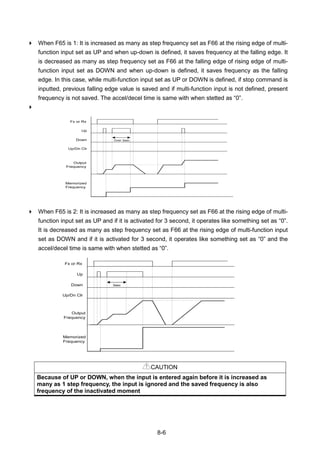
![8-7
8.4 3-Wire
Group Display Parameter Name Setting Range Default Unit
I/O
group
I17
[Multi-function Input terminal
P1 select]
0
0 ~ 27
0
~ ~
I24
[Multi-function Input
terminal P8 select]
17 7
Select the terminal from P1-P8 for use as 3-Wire operation.
If P8 is selected, set I24 to 17 {3-Wire operation}.
Input signal is latched (saved) in 3-Wire operation. Therefore, inverter can be operated by
Push-button switch.
The bandwidth of pulse (t) should not be less than 50msec.
8.5 Dwell operation
Group Display Parameter Name Setting Range Default Unit
Function
group 2
H 7 [Dwell frequency] - 0.1 ~ 400 5.00
Hz
H 8 [Dwell time] - 0 ~ 10 0.0 sec
In this setting, motor begins to accelerate after dwell operation is executed for dwell time
at the dwell frequency.
It is mainly used to release mechanical brake in elevators after operating at dwell
frequency.
Dwell frequency: This function is used to output torque in an intended direction. It is useful in
hoisting applications to get enough torque before releasing a mechanical brake. Rated Slip
frequency is calculated by the formula shown below.
P1
P2
P8
CM
FX : I17 = 0
RX : I18 = 1
3-Wire : I24 = 17
FX
RX
Frequency
P8 (3-Wire)
t](https://image.slidesharecdn.com/ig5amanualv2-200106075958/85/I-g5a-manual_v2-4_-110131-109-320.jpg)
![8-8
8.6 Slip compensation
Group Display Parameter Name Setting Range Default Unit
Function
group 2
H30
[Motor type select]
- 0.2 ~ 22 7.5
H31 [Number of motor poles] - 2 ~ 12 4
H32 [Rated slip frequency] - 0 ~ 10 2.33 Hz
H33 [Motor rated current] - 0.5 ~ 150 26.3 A
H34 [Motor No Load Current] - 0.1 ~ 50 11.0 A
H36 [Motor efficiency] - 50 ~ 100 87 %
H37 [Load inertia rate] - 0 ~ 2 0
H40 [Control mode select] 1 0 ~ 3 0
Set H40 – [Control mode select] to 1 {Slip compensation}.
This function enables the motor to run in constant speed by compensating inherent slip in
an induction motor.
H30: Set the motor type connected to the inverter output side.
H30 [Motor type select] 0.2 0.2kW
~
22.0 22.0kW
H31: Enter the pole number on the Motor nameplate.
H32: Enter the slip frequency in accordance with the following formula and motor nameplate.
120
Prpm
ff rs
Where, sf = Rated slip frequency
rf = Rated frequency
rpm = Motor rated RPM
P = Motor pole number
Ex) Rated freq.: 60Hz, Rated RPM: 1740rpm, Poles: 4,
Hzfs 2
120
41740
60
Frequency
Run
command
Dwell time
Dwell freq.
Start freq.](https://image.slidesharecdn.com/ig5amanualv2-200106075958/85/I-g5a-manual_v2-4_-110131-110-320.jpg)
![8-9
H33: Enter the motor nameplate rated current.
H34: Enter the measured current when the motor is running at rated frequency after the load is
removed. Enter 50% of the rated motor current when it is difficult to measure the motor no load
current.
H36: Enter motor efficiency on the nameplate.
H37: Select load inertia based on motor inertia as shown below.
H37 [Load inertia
rate] 0
Less than 10 times motor
inertia
1
About 10 times motor
inertia
2
Greater than 10 times motor
inertia
As the loads are heavier, the speed gap between rated RPM and synchronous speed is
widening (see the figure below). This function compensates for this inherent slip.
Synchronous
speed
Motor rated
RPM
RPM
Load
Slip
compensation
8.7 PID control
Group Display Parameter Name Setting Range Default
Uni
t
Function
group 2
H49 [PID Operation select] 1 0 ~ 1 0 -
H50 [PID Feedback select] - 0 ~ 1 0 -
H51 [P gain for PID controller] - 0 ~ 999.9 300.0 %
H52
[Integral time for PID controller
(I gain)]
- 0.1~ 32.0 1.0 sec
H53
[Differential time for PID
controller (D gain)]
- 0.0~30.0 0 sec
H54 [PID mode select] - 0 ~ 1 0 -
H55 [PID output frequency high limit] - 0.1 ~ 400 60.0 Hz
H56 [PID output frequency low limit] - 0.1 ~ 400 0.50 Hz
H57 [PID reference select] - 0~4 0 Hz
H58 [PID unit select] - 0~1 0 -
H61 [Sleep delay time] - 0.0~2000.0 60.0 -
H62 [Sleep frequency] - 0.00~400 0.00 Hz
H63 [Wake-up level] - 0.0~100.0 35.0 %](https://image.slidesharecdn.com/ig5amanualv2-200106075958/85/I-g5a-manual_v2-4_-110131-111-320.jpg)
![8-10
Group Display Parameter Name Setting Range Default
Uni
t
I/O
group
I17~
I24
[Multi-function input terminal
P1-P8 define]
21 0 ~ 27 - -
Drive
group
rEF [PID reference] -
0~400
/0~100
0.00
/0.0
Hz
/%
Fbk [PID feedback] -
0~400
/0~100
0.00
/0.0
Hz
/%
In order to control the amount of following water, pressure and temperature, do PID
control to inverter output frequency.
Select H49 of function group 2 as a 1 (PID drive select). Then REF and FBK category
show. Set PID reference value in REF and real PID feedback amount is monitored at the
FBK
PID drive is classified as two which are Normal PID mode and Process PID mode. It can
be set in the H54 (PID mode select)
H50: Select the feedback type of PID controller.
H50 [PID Feedback
select]
0 Terminal I input (0 ~ 20[mA] )
1 Terminal V1 input (0 ~ 10[V])
H51: Set the percentage of output to error. If P Gain is set to 50%, 50% of the error value will
be output. Higher value can reach the target control value faster but it may cause oscillation.
H52: Set the time to output the accumulated error value. Set the time required to output 100%
when the error value is 100%. If H52 - [Integral time for PID controller (I gain)] is set to 1 sec
and the error becomes 100%, 100% will be output in 1 sec. Adjusting the value may reduce the
nominal error. If the value is reduced, response will be faster but setting too low may lead to
controller oscillation.
H53: Set the output value to the variation of the error. The error is detected by 0.01 sec in SV-
iG5A. If differential time is set to 0.01 sec and the percentage variation of error per 1 sec is
100%, 1% per 10msec is output.
H54: PID Feed Forward Gain. Set the gain to add the target value to the PID controller output.
H55, H56: It limits the output of the PID controller.
H57: selects PID Reference
H58: PID Reference and PID feedback‟s units are classified as two which is [Hz] and [%].
H58=0: [Hz], H58=1: [%]
I17 ~ I24: To exchange PID to normal operation, set one of P1-P8 terminal to 21 and turn ON.
rPM: Calculates the feedback from H50 into Motor frequency and displays it.
rEF: indicates PID controller‟s command value.
Fbk: converts feedback amount set in H50 to motor frequency.](https://image.slidesharecdn.com/ig5amanualv2-200106075958/85/I-g5a-manual_v2-4_-110131-112-320.jpg)
![8-11
Normal PID drive (H54=0)
PID control diagram
0
1
2
H50:PID F/B
PID F/B Select
Func. Group 2
Communi-
cation 3)
V1_2
0 ~ +10 [V]
I
0 ~ 20 [mA]
KP
KI/s
KDs
H51 : P Gain
PID Gain
Func. Group 2
H52 : I Gain
H53 : D Gain
H55 : H-Limit
PID Limit
Func. Group 2
H56 : L-Limit
I/O Group
I 1, 6, 11
I/O Group
I 2 ~ I15
Analog Input
Filter
Analog Input
Scale
V1_2 : 0 ~ 10V
I : 0 ~ 20mA
1
0
2 Communication
PID Command
Select
Communi-
cation
I/O Group
I 1, 6, 11
Analog Input
Filter
I/O Group
I 2 ~ I15
Analog Input
Scale
V1_2
0 ~ +10 [V]
I
0 ~ 20 [mA]
Keypad or
Remote Keypad
Func. Group 2
H 57
Keypad Setting 2
V1_2 : 0 ~ 10V
I : 0 ~ 20mA
1
2
3
4
Keypad Setting 10
Communication
H58 = 0 : Frequency Operation Concept
H58 = 1 : % Operation Concept 9)
PID REF 4)
PID FBK 5)
Frequency Conversion 6)
PID Output
Frequency 7)
PID Operation
Change 6)
01
2
3
4
PID OUT 8)
I17~I24
Mult Function
Input
I/O Group
3) Adds RS-485 communications to PID Feedback category.
4) PID REF value can be changed and checked in the “rEF” of the DRV group.
Unit is [Hz] when H58=0 and [%] when H58=1
5) PID FBK value cab be checked in the “Fbk” of the DRV group
Unit is sane with the “rEF”
6) If PID switching is inputted to the multi-input (P1~P8), though H58 is 1, [%] is converted into [Hz].
7) Output frequency is displayed in the “SPD” of DRV group.
8) PID OUT of Normal PID is single polarity and it is limited by H55 (H-Limit) and H56 (L-Limit).
9) 100% is F21 (Max. frequency)](https://image.slidesharecdn.com/ig5amanualv2-200106075958/85/I-g5a-manual_v2-4_-110131-113-320.jpg)
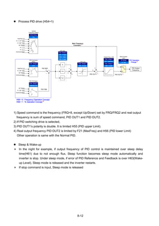
![8-13
Sleep Freq Wake up level
PID Reference
PID Feedback
Output
frequency
RUN command
PID Active
Sleep Delay
8.8 Auto-tuning
Group Display Parameter Name Setting Range Default Unit
Function
group 2
H41 [Auto tuning] 1 0 ~ 1 0 -
H42 [Stator resistance (Rs)] - 0 ~ 28 -
H44 [Leakage inductance (L)] - 0 ~ 300.00 - mH
Automatic measuring of the motor parameters is provided.
The measured motor parameters in H41 can be used in Auto Torque Boost and
Sensorless Vector Control.
CAUTION
Auto tuning should be executed after stopping the motor. Motor shaft must not run by the load
during H41 – [Auto tuning].
H41: When H41 is set to 1 and press the Enter () key, Auto tuning is activated and “TUn” will
appear on the LED keypad. When finished, “H41” will be displayed.
H42, H44: The values of motor stator resistance and leakage inductance detected in H41 are
displayed, respectively. When Auto tuning is skipped or H93 – [Parameter initialize] is done, the
default value corresponding to motor type (H30) will be displayed.
Press the STOP/RST key on the keypad or turn on the EST terminal to stop the Auto Tuning.
If Auto tuning of H42 and H44 is interrupted, the default value will be set. If H42 and H44 are
finished and auto-tuning of leakage inductance is interrupted, the measured value of H42 and
H44 are used and the default of leakage inductance is set.
See page 8-16 for motor parameter default values.
CAUTION
Do not enter any incorrect value as stator resistance and leakage inductance. Otherwise,
the function of Sensorless vector control and Auto torque boost could be deteriorated.](https://image.slidesharecdn.com/ig5amanualv2-200106075958/85/I-g5a-manual_v2-4_-110131-115-320.jpg)
![8-14
8.9 Sensorless Vector Control
Group Display Parameter Name Setting Range Default Unit
Function
group 2
H40 [Control mode select] 3 0 ~ 3 0 -
H30 [Motor type select] - 0.2 ~ 22.0 - kW
H32
[Rated
slip frequency]
- 0 ~ 10 - Hz
H33 [Motor rated current] - 0.5 ~ 150 - A
H34 [Motor No Load Current] - 0.1 ~ 20 - A
H42 [Stator resistance (Rs)] - 0 ~ 28 -
H44
[Leakage inductance
(L)]
- 0~300.00 - mH
Function
group 1
F14
[Time for energizing a
motor]
- 0.0~60.0 0.1 sec
If H40 – [Control mode select] is set to 3, Sensorless vector control will become active.
CAUTION
Motor parameters should be measured for high performance. It is highly recommended H41 –
[Auto tuning] be done prior to proceeding operation via Sensorless vector control.
Ensure that the following parameters are entered correctly for high performance in Sensorless
vector control.
H30: Select motor type connected to inverter output.
H32: Enter rated slip frequency based on motor nameplate RPM and rated frequency (See 8-8).
H33: Enter motor nameplate rated current.
H34: After removing the load, select H40 – [Control mode select] to 0 {V/F control} and run the
motor at 60Hz. Enter the current displayed in Cur-[Output current] as motor no load current. If it
is difficult to remove the load from the motor shaft, enter the value either 40 to 50% of the H33
– [Motor rated current] or the factory default.
In case that occur torque riffle while high speed driving, lower H34-[No load current] to 30%.
H42, H44: Enter the value of the parameter measured during H41 – [Auto tuning] or the factory
default.
F14: This parameter accelerates the motor after pre-exciting the motor for the set time. The
amount of the pre-exciting current is set in H34- [Motor no load current].
Directly enter the motor nameplate value except motor rating when 0.2kW is used.](https://image.slidesharecdn.com/ig5amanualv2-200106075958/85/I-g5a-manual_v2-4_-110131-116-320.jpg)
![8-15
Factory default by motor ratings
Input
voltage
Motor rating
[kW]
Current
rating
[A]
No-load
current
[A]
Rated slip
freq
[Hz]
Stator
resistance
[]
Leakage
inductance
[mH]
200
0.2 1.1 0.6 2.33 14.0 122.00
0.4 1.8 1.2 3.00 6.70 61.00
0.75 3.5 2.1 2.33 2.46 28.14
1.5 6.5 3.0 2.33 1.13 14.75
2.2 8.8 4.4 2.00 0.869 11.31
3.7 12.9 4.9 2.33 0.500 5.41
5.5 19.7 6.6 2.33 0.314 3.60
7.5 26.3 11.0 2.33 0.196 2.89
11.0 37.0 12.5 1.33 0.120 2.47
15.0 50.0 17.5 1.67 0.084 1.12
18.5 62.0 19.4 1.33 0.068 0.82
22.0 76.0 25.3 1.33 0.056 0.95
400
0.2 0.7 0.4 2.33 28.00 300.00
0.4 1.1 0.7 3.0 14.0 177.86
0.75 2.0 1.3 2.33 7.38 88.44
1.5 3.7 2.1 2.33 3.39 44.31
2.2 5.1 2.6 2.00 2.607 34.21
3.7 6.5 3.3 2.33 1.500 16.23
5.5 11.3 3.9 2.33 0.940 10.74
7.5 15.2 5.7 2.33 0.520 8.80
11.0 22.6 7.5 1.33 0.360 7.67
15.0 25.2 10.1 1.67 0.250 3.38
18.5 33.0 11.6 1.33 0.168 2.46
22.0 41.0 13.6 1.33 0.168 2.84
8.10 Energy-saving operation
Group Display Parameter Name Setting Range Default Unit
Function
group 1
F40
[Energy-saving
operation]
- 0 ~ 30 0 %
Set the amount of output voltage to be reduced in F40.
Set as the percent of Max output voltage.
For fan or pump applications, energy consumption can be dramatically reduced by
decreasing the output voltage when light or no load is connected.
Current
Output voltage
F40](https://image.slidesharecdn.com/ig5amanualv2-200106075958/85/I-g5a-manual_v2-4_-110131-117-320.jpg)
![8-16
8.11 Speed search
Group Display Parameter Name Setting Range Default Unit
Function
group 2
H22 [Speed search select] - 0 ~ 15 0
H23 [Current level] - 80 ~ 200 100 %
H24 [Speed search P gain] -
0 ~ 9999
100
H25 [Speed search I gain] - 200
I/O group I54
[Multi-function output
terminal select]
15
0 ~ 19
12
I55 [Multi-function relay select] 15 17
This is used to prevent possible fault from occurring if the inverter outputs the voltage
during operation after the load is removed.
The inverter estimates the motor rpm based on output current. Therefore, detecting exact
speed is difficult.
The following table shows 4 types of Speed search selection.
H22 Speed search
during H20 –
[Power ON start]
Speed search
during Instant
Power Failure
restart
Speed search
during H21-
[Restart after
fault reset]
Speed search
during
Acceleration
Bit 3 Bit 2 Bit 1 Bit 0
0 - - - -
1 - - -
2 - - -
3 - -
4 - - -
5 - -
6 - -
7 -
8 - - -
9 - -
10 - -
11 -
12 - -
13 -
14 -
15
H23: Limits current during Speed search. Set as the percent of H33.
H24, H25: Speed search is activated via PI control. Adjust P gain and I gain corresponding to
the load characteristics.
I54, I55: Signal of active Speed search is given to external sequence via Multi-function output
terminal (MO) and Multi-function relay output (3ABC).](https://image.slidesharecdn.com/ig5amanualv2-200106075958/85/I-g5a-manual_v2-4_-110131-118-320.jpg)
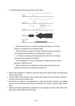
![8-18
8.12 Auto restart try
Group Display Parameter Name Setting Range Default Unit
Function
group 2
H26 [Number of Auto Restart try] - 0 ~ 10 0
H27 [Auto Restart time] - 0 ~ 60 1.0 sec
This parameter sets the number of times auto restart is activated in H26.
It is used to prevent the system down caused by internal protection function activated by
the causes such as noise.
H26: Auto restart will become active after the H27. H26 – [Number of Auto restart try] is
reduced by 1 when it is active. If the trip outnumbers the preset restart try, auto restart function
is deactivated. If the setting is reset via the control terminal or the STOP/RST key on the
keypad, the number of auto restart try set by user is automatically entered.
If there is no more trip occurring for 30 sec after Auto restart operation, the H26 is restored to
the preset value.
When operation is stopped due to Low voltage {Lvt} or Emergency stop {EST}, Inverter
Overheat {Oht}, and Hardware Trip {HWt}, Auto restart will be deactivated.
After the H27- [Auto Restart time], the motor starts acceleration automatically via speed search
(H22-25).
The following pattern is shown when the H26 – [Number of auto restart try] is set to 2.
Run
Command
Constant
Run
Number of Auto
restart try
2 1 2 1 0 2
Freq
Voltage
Reset
30Sec
Speed Search
operation
Trip occurred
H27](https://image.slidesharecdn.com/ig5amanualv2-200106075958/85/I-g5a-manual_v2-4_-110131-120-320.jpg)
![8-19
8.13 Operating sound select (Carrier frequency change)
Group Display Parameter Name Setting Range Default Unit
Function
group 2
H39 [Carrier frequency] - 1 ~ 15 3 kHz
This parameter affects the sound of the inverter during operation.
H39 When setting carrier frequency
high,
Motor sound reduced
Inverter heat loss increased
Inverter noise increased
Inverter leakage current
increased
8.14 2nd
motor operation
Group Display Parameter Name Setting Range Default Unit
Function
group 2
H81 [2nd motor accel time] - 0 ~ 6000 5.0 sec
H82 [2nd motor decel time] - 0 ~ 6000 10.0 sec
H83 [2nd motor base freq.] - 30 ~ 400 60.00 Hz
H84 [2nd motor V/F pattern] - 0 ~ 2 0
H85
[2nd motor Positive torque
boost]
- 0 ~ 15 5 %
H86
[2nd motor Negative torque
boost]
- 0 ~ 15 5 %
H87
[2nd motor stall prevention
level]
- 30 ~ 150 150 %
H88
[2nd motor electronic thermal
level for 1 min]
- 50 ~ 200 150 %
H89
[2nd motor electronic thermal
level for continuous operation]
- 50 ~ 150 100 %
H90 [2nd motor rated current] - 0.1~100 26.3 A
I/O
group
I17
[Multi-function Input terminal
P1Function select]
-
0 ~ 27
0
~ ~
I24
[Multi-function Input
terminal P8Function select]
12 7
Set the terminal among Multi-function input P1 thru P5 for second motor operation.
To define the terminal P5 as second motor operation, set I24 to 12.](https://image.slidesharecdn.com/ig5amanualv2-200106075958/85/I-g5a-manual_v2-4_-110131-121-320.jpg)
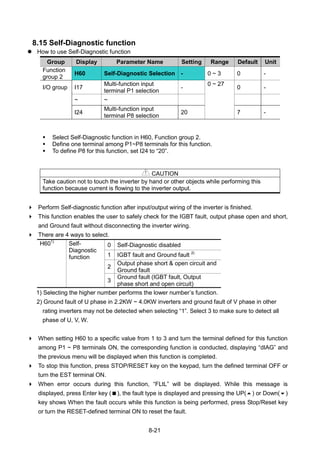
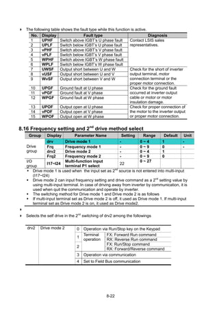
![8-23
Selects the self drive in the 2nd
switching of Frq2 among the followings
Frq2 Frequency mode
2
0
Digital
Keypad digital frequency mode1
1 Keypad digital frequency mode2
2
Analog
V1 terminal setting1: -10 ~ +10V
3 V1 terminal setting2: 0 ~ +10V
4 I terminal: 0 ~ 20mA
5 V1 terminal setting1 + I terminal
6 V1 terminal setting2 + I terminal
7 Setting via RS-485 communication
8 Up-Down (Digital Volume) run
9 Set to FieldBus communication
The following is example for switching of drv1 and drv2.
Group Display Parameter Name Setting Range Default Unit
Drive
group
drv Drive mode 1 3 0 ~ 4 1 -
Frq Frequency mode 1 0 0 ~ 9 0 -
drv2 Drive mode 2 1 0 ~ 4 1
Frq2 Frequency mode 2 0 0 ~ 9 0
I/O
group
I24
Multi-function input
terminal P8 input terminal
22 0 ~ 27 7
The following figure is drawn when setting is like the above and command frequency is 30 [Hz],
F4 [stop method]=0
FX
Output Freq.
1 2
30.00
Communication FX
P8 : 2nd Change
3 4 5
① Accelerate for accel time up to setting frequency by Drive 1 mode, FX signal.
② Drive continuously under FX is ON because DRV2 is 1 when P8 terminal input is ON and
change into 2nd
.
③ Stop gradually as stop command because DRV is communication drive when P8 terminal
input is OFF and change into 1st.
④ Accelerate up to setting frequency for Drive 1 mode, FX signal is ON.
⑤ Stop gradually under FX is OFF because DRV2 is 1 when P8 terminal input is ON and
change into 2nd
.
CAUTION
If you press ON while multi-function input terminal (P1 ~ P8) is set to 2nd
Source,
frequency command and drive command is changed to Drive mode 2. So you
should check Drive mode 2 before input multi-function terminal.](https://image.slidesharecdn.com/ig5amanualv2-200106075958/85/I-g5a-manual_v2-4_-110131-125-320.jpg)
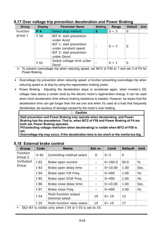
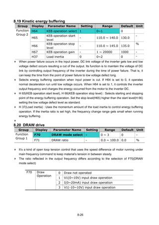
![8-27
Select 1 and 2 for F70
The center value of analogue input (selected by the set value of I6~I15) as
standard, if the input is big it gets (+), if small (-) and gets reflected in the
output frequency as the ratio set in F71.
Select 3 for F70
OV as standard, if analog input voltage is big, it gets (+), if small (-) and gets
reflected in the output frequency as the ratio set in F71.
1st/2nd
Frequency Select
Communi-
cation
I/O Group
I 6, 11
Analog Input
Filter
I/O Group
I 7 ~ I15
Analog Input
Scale
V1_2
0 ~ +10 [V]
I
0 ~ 20 [mA]
Keypad or
Remote Keypad
Drive Group
Frq/Frq2
012
3
4
5
6
7
8
Keypad Setting 2
V1_2 : 0 ~ 10V
I : 0 ~ 20mA
1
3
4
7
Keypad Setting 10
Communication
8
Mult-step Freq.
Mult-step
Freq. Select
Digital Input
FilterP1
P2
P3
P4
P5
P6
P7
P8
I 27
I/O Group
I17 ~ I24
5,6,7
I/O Group
St1~St3
I30~I33
Drive Group
I/O Group
V1_2 Mode
I Mode
1
2
NONE0
Func. Group 1
F70 : DRAWMODE
V1_2
0 ~ +10 [V]
I
0 ~ 20 [mA]
I/O Group
I 6, 11
I/O Group
I3 ~ I15
Center Freq.
Func. Group 1
F71
K
Final Reference
Frequency
V1_1 Mode3
V1_1
-10 ~ 10 [V]
Func. Group 1
F70
Func. Group 1
F70
F70 = 3
I17~I24
I/O Group
JOG FrequencyV1_1 : -10 ~ 10V2
DRAW operation example
If draw operation is set to 30Hz, F70=3(V1: -10V ~10V), F71=10.0% selected,
(I3~I15 = plant shipment) Frequency that gets changed by DRAW operation is
27Hz(V1=-10V) ~33Hz(V1=10V)
Caution
When operating DRAW, set command frequency to FRQ/FRQ2 and set the
rest of it from F70(DRAW mode select). For example, if FRQ=2(V1) and
F70=1(V1), it does not operate.](https://image.slidesharecdn.com/ig5amanualv2-200106075958/85/I-g5a-manual_v2-4_-110131-129-320.jpg)
![8-28
8.21 2 Phase PWM drive
Group Display Parameter Name Setting Range Default Unit
Function
Group 2
H48 PWM controlling mode
0: NORMAL PWM
1: 2 phase PWM
1 0 ~ 2 0
Heat loss and leakage current from inverter can be reduced when H48 is set to 1(2 phase
PWM) according to the ratio of load.
8.22 Cooling fan control
Group Display Parameter Name Setting Range Default Unit
Function
group 2
H77 [Cooling fan control] 1 0 ~ 1 0
Control the On/ Off of the cooling fan to cool the Inverter heatsink.
When it is set to 0:
-. Cooling fan begins to operate when power ON.
-. Cooling fan is stopped when inverter main circuit voltage becomes low voltage due to power off.
When it is set to 1:
-. Cooling fan begins to operate when power is turned ON with operating command ON.
-. Cooling fan is stopped when operating command is turned Off with inverter output shut off.
-. Cooling fan keeps operating when heat sink temperature exceeds a certain limit regardless of
operating command.
-. Used when frequent Run/Stop or quite stop is required. This may make the cooling fan life
longer.
8.23 Operating mode select when cooling fan trip occurs
Group Display Parameter Name Setting Range Default Unit
Function
group 2
H78
[Operating mode when
cooling fan trip occurs]
- 0 ~ 1 0 -
I/O group I54
[Multi-function output
terminal select]
18 0 ~ 19 12 -
I55 [Multi-function relay select] 18 0 ~ 19 17 -
Select 0 or 1 in H78 code.
If H78 code is set to 0 (continuous operation), alarm can be output in I54 or I55.
0: continuous operation when cooling fan trip occurs.
-. Operation is not stopped regardless of cooling fan trip.
-. When I54 or I55 is set to 18 (cooling fan fault alarm), fault alarm signal can be output using
Multi-function output terminal or Multi-function relay.](https://image.slidesharecdn.com/ig5amanualv2-200106075958/85/I-g5a-manual_v2-4_-110131-130-320.jpg)

![8-30
8.24 Parameter read/write
Group Display Parameter Name Setting Range Default Unit
Function
group 2
H91 [Parameter read] 1 0 ~ 1 0
H92 [Parameter write] 1 0 ~ 1 0
Used to read/write Inverter Parameters using remote keypad.
CAUTION
Take caution when Parameter write (H92) is executed. By doing this, parameters in inverter
are cleared and parameters in remote keypad are copied to inverter.
Parameter read
Step Note Keypad display
1 Move to H91 code. H91
2 Press Enter () key once. 0
3 Press Up () key once. Rd
4 Press Enter () key twice. rd
5 H91 is displayed when Parameter read is finished. H91
Parameter write
Step Note Keypad display
1 Move to H92 code. H92
2 Press Enter () key once. 0
3 Press Up () key once. Wr
4 Press Enter () key twice. Wr
5 H91 is displayed when Parameter read is finished. H92
Inverter
Remote
keypad
Parameter Write(H92)
Parameter Read(H91)](https://image.slidesharecdn.com/ig5amanualv2-200106075958/85/I-g5a-manual_v2-4_-110131-132-320.jpg)
![8-31
8.25 Parameter Initialize / Lock
Parameter initialize
Group Display Parameter Name Range Default
Function
group 2
H93 [Parameter initialize] 0 - 0
1 4 groups initialize
2 Drive group initialize
3 F 1 group initialize
4 F 2 group initialize
5 I/O group initialize
Select the group to be initialized and perform it in H93 code.
Press Enter () key after setting in H93. H93 will be displayed again after initialization is
complete.
Password register
Group Display Parameter Name Setting Range Default Unit
Function
group 2
H94 [Password register] - 0 ~ FFFF 0
H95 [Parameter lock] - 0 ~ FFFF 0
Register password for Parameter lock (H95).
Password should be Hex decimal. (0 ~ 9, A, B, C, D, E, F)
CAUTION
After setting modification lock function of H95, Do not forget the registered
password. if you try to release lock, you need the registered password.
Factory default password is 0. Enter the new password except 0.
Follow the steps below when you register the password for the first time.
Step Note Keypad display
1 Move to H94 code. H94
2 Press Enter () key twice. 0
3 Register password. (Ex: 123) 123
4 123 will blink when Enter () key is pressed. 123
5 Press Enter () key. H94](https://image.slidesharecdn.com/ig5amanualv2-200106075958/85/I-g5a-manual_v2-4_-110131-133-320.jpg)
![9-1
CHAPTER 9 - MONITORING
9.1 Operating status monitoring
Output current
Group Display Parameter Name Setting Range Default Unit
Drive group CUr [Output current] -
Inverter output current can be monitored in Cur.
Motor RPM
Group Display Parameter Name Setting Range Default Unit
Drive group rPM [Motor RPM] -
Function
group 2
H31 [Number of motor poles] - 2 ~ 12 4
H49 [PID control select] - 0 ~ 1 0
H74
[Gain for Motor rpm
display]
- 1 ~ 1000 100 %
Motor rpm can be monitored in rPM.
When H40 is set to 0 {V/F control} or 1 {PID control}, the Inverter output frequency (f) is
displayed in RPM using the formula below. Motor slip is not considered.
In case that H49 code is 1, Feed back amount is converted into frequency.
H31: Enter the number of rated motor poles on the nameplate.
H74: This parameter is used to change the motor speed display to rotating speed (r/min) or
mechanical speed (m/min).
Inverter DC Link Voltage
Group Display Parameter Name Setting Range Default Unit
Drive group dCL [Inverter DC Link Voltage] -
Inverter DC link voltage can be monitored in dCL.
2 times the value of input voltage is displayed while motor is at a stop.
100
74
31
120 H
H
f
RPM
](https://image.slidesharecdn.com/ig5amanualv2-200106075958/85/I-g5a-manual_v2-4_-110131-135-320.jpg)
![9-2
User display select
Group Display Parameter Name Setting Range Default Unit
Drive group vOL [User display select] -
Function
group 2
H73 [Monitoring item select] - 0 ~ 2 0
The selected item in H73- [Monitoring item select] can be monitored in vOL- [User display
select.
If output power or torque is selected, Por or tOr will be displayed.
H73: Select one of the desired item numbers.
H73 [Monitoring item
select]
0 Output voltage [V]
1
Output power
[kW]
2 Torque [kgf m]
Enter motor efficiency indicated on motor nameplate to H36 to display correct torque.
Power on display
Group Code Parameter Setting range Initial
Function
group 2
H72 [Power on display] 0 Frequency command (0.00) 0
`
1 Accel time (ACC)
2 Decel time (DEC)
3 Drive mode (drv)
4 Frequency mode (Frq)
5 Multi-step frequency 1(St1)
6 Multi-step frequency 2(St2)
7 Multi-step frequency 3(St3)
8 Output current (CUr)
9 Motor rpm (rPM)
10 Inverter DC link voltage (dCL)
11 User display select (vOL)
12 Fault display 1(nOn)
13 Operating direction select (drC)
14 Output current 2
15 Motor rpm 2
16 Inverter DC link voltage 2
17 User display select 2
Select the parameter to be displayed on the keypad when Power ON.
The output current, motor rpm, DC link voltage and User display select are displayed
directly when 14~17 are set.](https://image.slidesharecdn.com/ig5amanualv2-200106075958/85/I-g5a-manual_v2-4_-110131-136-320.jpg)
![9-3
9.2 Monitoring the I/O terminal
Input terminal status monitoring
Group Display Parameter Name Setting Range Default Unit
I/O group I25
[Input terminals status
display]
-
Current input terminal status (ON/Off) can be monitored in I25.
The following is displayed when P1, P3, P4 are ON and P2, P5 are OFF.
Output terminal status monitoring
Group Display Parameter Name Setting Range Default Unit
I/O group I26
[Output terminals status
display]
-
Current output terminals (MO, relays) status (ON/Off) can be monitored in I26.
The followings are displayed when Multi-function output terminal (MO) is ON with Multi-function
relay OFF.
P8 P7 P6 P5 P4 P3 P2 P1
(ON)
(OFF)
3AC MO
(ON)
(OFF)](https://image.slidesharecdn.com/ig5amanualv2-200106075958/85/I-g5a-manual_v2-4_-110131-137-320.jpg)
![9-4
9.3 Monitoring fault condition
Monitoring current fault status
Group Display Parameter Name Setting Range Default Unit
Drive group nOn [Current Fault Display] -
Fault occurred during operation is displayed in nOn.
Up to 3 kinds of faults can be monitored.
This parameter gives information on fault types and the operating status at the time of the fault.
Refer to Page 4-11 or 9-5 for keypad setting.
Fault
types
Frequency
Current
Accel/Decel
Information Fault during Accel
Fault during Decel
Fault during constant run
Refer to Page 12-1 on fault types.
Fault History Monitoring
Group Display Parameter Name Setting Range Default Unit
Function
group 2
H 1 [Fault history 1] -
~ ~
H 5 [Fault history 5]
H 6 [Reset fault history] - 0 ~ 1 0
H 1 ~ H 5: Up to 5 faults information is stored.
H 6: Previous fault information stored in the code H1 thru H5 is all cleared.
When a fault occurs during operation, it can be monitored in the nOn.](https://image.slidesharecdn.com/ig5amanualv2-200106075958/85/I-g5a-manual_v2-4_-110131-138-320.jpg)
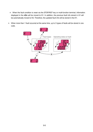
![9-6
9.4 Analog Output
Group Display Parameter Name Setting Range Default Unit
I/O group I50 [Analog output item select] - 0 ~ 3 0
I51
[Analog output level
adjustment]
- 10 ~ 200 100 %
Output item and the level from the AM terminal are selectable and adjustable.
I50: The selected item will be output to Analog output terminal (AM).
I50 Analog output
item select
Item corresponding to 10V
200V 400V
0 Output frequency. Max Frequency (F21)
1 Output current
150% of Inverter rated
current
2 Output voltage 282Vac 564Vac
3
Inverter DC link
voltage
400Vdc 800Vdc
I51: If you want to use Analog output value as a gauge input, the value can be adjustable
according to various gauge specifications.
AM
CM
0 ~ 10Vdc](https://image.slidesharecdn.com/ig5amanualv2-200106075958/85/I-g5a-manual_v2-4_-110131-140-320.jpg)
![9-7
9.5 Multi-function output terminal (MO) and Relay (3AC)
Group Code Parameter Setting range Initial
I/O
group
I54
[Multi-function
output terminal
select]
0 FDT-1 12
1 FDT-2
I55
[Multi-function
relay select]
2 FDT-3 17
3 FDT-4
4 FDT-5
5 Overload {OLt}
6 Inverter Overload {IOLt}
7 Motor stall {STALL}
8 Over voltage trip {OV}
9 Low voltage trip {LV}
10 Inverter overheat {OH}
11 Command loss
12 During run
13 During stop
14 During constant run
15 During speed searching
16 Wait time for run signal input
17 Fault output
18 Cooling fan trip alarm
19 Brake control signal
I56
[Fault relay
output]
When
setting the
H26–
[Number
of auto
restart
tries]
When the
trip other
than low
voltage
trip occurs
When the
low
voltage
trip occurs
Bit 2 Bit 1 Bit 0
0 - - - 2
1 - -
2 - -
3 -
4 - -
5 -
6 -
7
Select the desired item to be output via MO terminal and relay (30AC).](https://image.slidesharecdn.com/ig5amanualv2-200106075958/85/I-g5a-manual_v2-4_-110131-141-320.jpg)
![9-8
I56: When 17 {Fault display} is selected in I54 and I55, Multi-function output terminal and relay
will be activated with the value in I56.
0: FDT-1
Check whether the output frequency matches the user-setting frequency.
Active condition: Absolute value (preset frequency - output frequency) <= Frequency Detection
Bandwidth/2
Group Display Parameter Name Setting Range Default Unit
I/O group I53
[Detected Frequency
Bandwidth]
- 0 ~ 400 10.00 Hz
Cannot be set above Max frequency (F21).
When setting I53 to 10.0
1: FDT-2
Activated when the preset frequency matches frequency detection level (I52) and FDT-
1 condition is met.
Active condition: (Preset frequency = FDT level) & FDT-1
Group Display Parameter Name Setting Range Default Unit
I/O group I52
[Detected Frequency
level]
-
0 ~ 400
30.00
Hz
I53
[Detected Frequency
Bandwidth]
- 10.00
Cannot be set above Max frequency (F21).
When setting I52 and I53 to 30.0 Hz and 10.0 Hz, respectively
15Hz
Freq.
setting
Freq.
MO
20Hz
40Hz
20Hz
40Hz
35Hz
Run
command
25Hz
Freq.
setting
Freq.
MO
30Hz
50Hz
Run
command](https://image.slidesharecdn.com/ig5amanualv2-200106075958/85/I-g5a-manual_v2-4_-110131-142-320.jpg)
![9-9
2: FDT-3
Activated when run frequency meets the following condition.
Active condition: Absolute value (FDT level - run frequency) <= FDT Bandwidth/2
Group Display Parameter Name Setting Range Default Unit
I/O group I52
[Detected Frequency
level]
-
0 ~ 400
30.00
Hz
I53
[Detected Frequency
Bandwidth]
- 10.00
Cannot be set above Max frequency (F21).
When setting I52 and I53 to 30.0Hz and 10.0 Hz, respectively
3: FDT-4
Activated when run frequency meets the following condition.
Active condition:
Accel time: Run Frequency >= FDT Level
Decel time: Run Frequency > (FDT Level – FDT Bandwidth/2)
Group Display Parameter Name Setting Range Default Unit
I/O group I52
[Detected Frequency
level]
-
0 ~ 400
30.00
Hz
I53
[Detected Frequency
Bandwidth]
- 10.00
Cannot be set above Max frequency (F21).
When setting I52 and I53 to 30.0Hz and 10.0 Hz, respectively
Freq.
MO
Run
command
25Hz
30Hz
35Hz
Freq.
MO
Run
command
25Hz
30Hz](https://image.slidesharecdn.com/ig5amanualv2-200106075958/85/I-g5a-manual_v2-4_-110131-143-320.jpg)
![9-10
4: FDT-5
Activated as B contact contrast to FDT-4.
Active condition:
Accel time: Run Frequency >= FDT Level
Decel time: Run Frequency > (FDT Level – FDT Bandwidth/2)
Group Display Parameter Name Setting Range Default Unit
I/O group I52
[Detected Frequency
level]
-
0 ~ 400
30.00
Hz
I53
[Detected Frequency
Bandwidth]
- 10.00
Cannot be set above Max frequency (F21).
When setting I52 and I53 to 30.0Hz and 10.0 Hz, respectively
5: Overload (OLt)
Refer to page 10-2.
6: Inverter Overload (IOLt)
Refer to page 10-6.
7: Motor stall (STALL)
Refer to page 10-3.
8: Over voltage trip (Ovt)
Activated when over voltage trip occurs due to DC link voltage exceeded 400Vdc for
200V class and 820Vdc for 400V class.
9: Low voltage trip (Lvt)
Activated when low voltage trip occurs due to DC link voltage under 180Vdc for 200V
class and 360Vdc for 400V class.
10: Inverter heatsink overheat (OHt)
Activated when the heatsink is overheated.
11: Command loss
Activated when Analog (V1,I) and RS485 communication commands are lost.
Freq.
MO
Run
command
25Hz
30Hz](https://image.slidesharecdn.com/ig5amanualv2-200106075958/85/I-g5a-manual_v2-4_-110131-144-320.jpg)
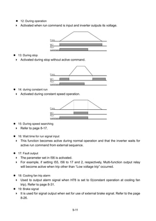
![9-12
9.6 Output terminal select at loder communication error
Group Display Parameter Name Setting Range Default Unit
I/O group I57
[Output terminal select
when communication
error with keypad]
- 0 ~ 3 0
Select relay output or open collector output when keypad-inverter communication fails.
Keypad and inverter CPU communication is made by serial communication, delivering
information. When communication error occurs for a certain time, will be
displayed and error signal can be output to MO or relays.
MFI output relay MFI output terminal
Bit 1 Bit 0
0 - -
1 -
2 -
3
0: Not used
1: Signal output to MO
2: Signal output to 3A, 3B contacts
3: Signal output to MO, 3A, 3B](https://image.slidesharecdn.com/ig5amanualv2-200106075958/85/I-g5a-manual_v2-4_-110131-146-320.jpg)
![10-1
CHAPTER 10 - PROTECTIVE FUNCTIONS
10.1 Electronic Thermal
Group Code Parameter Set Range Initial Unit
Function
group 1
F50
[ETH (Electronic thermal)
select]
1 0 ~ 1 0
F51
[Electronic thermal level for 1
minute]
- 50 ~ 200 150 %
F52
[Electronic thermal level for
continuous]
- 50 ~ 150 100 %
F53 [Motor type] - 0 ~ 1 0
Select F50 – [Electronic thermal select] to 1.
It activates when the motor is overheated (time-inverse). If current greater than set in F51
flows, inverter output is turned off for the preset time in F51- [Electronic thermal level for 1
minute].
F51: Enter the value of max current that is capable of flowing to the motor continuously for one
minute. It is set in percent of motor rated current. The value cannot be set lower than F52.
F52: Enter the amount of current for continuous operation. Normally motor rated current is
used. It cannot be set greater than F51.
F53: For an inductance motor, cooling effects decrease when a motor is running at low speed.
A special motor is a motor that uses a separately powered cooling fan maximize cooling effect
even in low speed.
F53 [Motor type]
0
Standard motors having a cooling fan directly
connected to the shaft
1
Special motor that uses a separately powered
cooling fan.
Current for
continuous [%]
100
95
65
20 60
Freq [Hz]
F53 = 1
F53 = 2](https://image.slidesharecdn.com/ig5amanualv2-200106075958/85/I-g5a-manual_v2-4_-110131-147-320.jpg)
![10-2
10.2 Overload Warning and trip
Overload warning
Group Code Parameter Set Range Initial Unit
Function
group 1
F54 [Overload warning level] - 30 ~ 150 150 %
F55 [Overload warning time] - 0 ~ 30 10 Sec
I/O
group
I54
[Multi-function output
terminal select]
5
0 ~ 19
12
I55 [Multi-function relay select] 5 17
Select one output terminal for this function between MO and 3ABC.
If selecting MO as output terminal, set I54 to 5 {Overload: OL}
F54: Set the value as a percent of motor rated current.
Current [%]
F51
F52
60 ETH trip time [sec]
Current
Multi-function
output
F54
t : Overload
warning timet t](https://image.slidesharecdn.com/ig5amanualv2-200106075958/85/I-g5a-manual_v2-4_-110131-148-320.jpg)
![10-3
Overload trip
Group Code Parameter Set Range Initial Unit
Function
group 1
F56 [Overload trip select] 1 0 ~ 1 1
F57 [Overload trip level] - 30 ~ 200 180 %
F58 [Overload trip time] - 0 ~ 60 60 sec
Set F56 to 1.
Inverter output is turned off when motor is overloaded.
Inverter output is turned off when excessive current flows to the motor for F58 – [Overload
trip time].
10.3 Stall prevention
Group Code Parameter Set Range Initial Unit
Function
group 1
F59 [Stall prevention select] - 0 ~ 7 0
F60 [Stall prevention level] - 30 ~ 200 150 %
I/O
group
I54
[Multi-function output terminal
select]
7
0 ~19
12
I55 [Multi-function relay select] 7 17
During acceleration: Motor starts deceleration when current exceeding the value set in
F60 flows.
During constant run: Motor decelerates when current exceeding the value set in F60
flows.
During deceleration: Motor deceleration is stopped when inverter DC link voltage rises
above a certain voltage level.
F60: The value is set as the percent of motor rated current (H33).
I54, I55: Inverter outputs signals through multi-function output terminal (MO) or relay
output (3ABC) or external sequence when stall prevention function is activated. Motor stall
status still can be monitored in these codes though F59 is not selected (000).
F59: Stall prevention can be set as the table below.
F59 Stall prevention
Setting
During
Deceleration
During
constant
speed
During
Acceleration
Bit 2 Bit 1 Bit 0
0 - - -
1 - -
2 - -
3 -
4 - -
5 -
6 -
7 ](https://image.slidesharecdn.com/ig5amanualv2-200106075958/85/I-g5a-manual_v2-4_-110131-149-320.jpg)
![10-4
For example, set F59 to 3 to make stall prevention active during Acceleration and constant run.
When stall prevention is executed during acceleration or deceleration, Accel/Decel time may
take longer than the user-setting time.
When stall prevention is activated during constant run, t1, t2 executed in accordance with the
value set in ACC - [Accel time] and dEC - [Decel time].
Current
Freq.
During
acceleration
During
constant run
F60
t1 t2
Multi-function
output or relay
DC
voltage
Freq.
During
deceleration
Multi-function
output or relay](https://image.slidesharecdn.com/ig5amanualv2-200106075958/85/I-g5a-manual_v2-4_-110131-150-320.jpg)
![10-5
10.4 Output phase loss protection
Group Code Parameter Set Range Initial Unit
Function
group 2
H19
[Input/Output phase loss
protection select]
1 0 ~ 3 0
Set H19 value to 1.
Output phase loss: Inverter output is shut off at the event of more than one phase loss
among U, V and W.
Input phase loss: Inverter output is blocked at the event of more than one phase loss
among R, S and T. If there is no input phase loss, output is shut off when it is time to replace
DC link capacitor.
CAUTION
Set H33 [Motor rated current] correctly. If the actual motor rated current and the value of H33
are different, output phase loss protection function could not be activated.
H19 [Input/Output
phase loss
protection select]
0 Not used
1 Output phase loss protection
2 Input phase loss protection
3 Input/output phase loss protection
10.5 External trip signal
Group Code Parameter Set Range Initial Unit
I/O
group
I17
[Multi-function input terminal P1
define]
0 ~ 27
0
~ ~
I23
[Multi-function input terminal
P7 define]
18 6
I24
[Multi-function input terminal
P8 define]
19 7
Select a terminal among P1 thru P8 to output external trip signal.
Set I23 and I24 to 18 and 19 to define P7 and P8 as External A contact and B contact.
External trip signal input A contact (N.O.): Normal open contact input. When a P7 terminal set
to “Ext trip-A” is ON (Closed), inverter displays the fault and turns off its output.
External trip signal input B contact (N.C.): Normal close contact input. When a P8 terminal set
to “Ext trip-B” is OFF (Open), inverter displays the fault and turns off its output.](https://image.slidesharecdn.com/ig5amanualv2-200106075958/85/I-g5a-manual_v2-4_-110131-151-320.jpg)
![10-6
10.6 Inverter Overload
Group Code Parameter Set Range Initial Unit
I/O
group
I54
[Multi-function output terminal
select]
6
0 ~ 19
12
I55 [Multi-function relay select] 6 17
Inverter overload prevention function is activated when the current above inverter rated current
flows.
Multi-function output terminal (MO) or Multi-function relay (3ABC) is used as the alarm signal
output during inverter overload trip.
10.7 Speed command loss
Group Code Parameter Set Range Initial Unit
I/O
group
I16
[Select criteria for analog speed
command loss]
0 0 ~ 2 0
I62
[Drive mode select at loss of
speed command]
- 0 ~ 2 0
I63
[Wait time after loss of speed
command]
- 0.1 ~ 120 1.0 sec
I54
[Multi-function output terminal
select]
11
0 ~ 19
12
I55 [Multi-function relay select] 11 17
Select the Drive mode when frequency reference set via Analog (V1, I) input terminal or
communication option is lost.
I16: This is to set the criteria for analog input signal loss.
I16 [Criteria for analog
input signal loss] 0
Disabled (Does not check the analog input
signal loss)
1
When half the value set in I2, I7, I12 is
entered
2
When less than the value set in I 2, I 7, I 12
is entered
P1
P7
P8
FX : I17 = 0
N.O. : I23 = 18
CM
N.C. : I24 = 19
P4(A contact)
Frequency
Run
command
P5(B contact)](https://image.slidesharecdn.com/ig5amanualv2-200106075958/85/I-g5a-manual_v2-4_-110131-152-320.jpg)
![10-7
Ex 1) The inverter determines the freq reference is lost when DRV- Frq is set to 3 (Analog
V1 input), I 16 to 1 and analog input signal is less than half the value set in I 7.
Ex 2) The inverter determines the freq reference is lost when DRV- Frq is set to 6 (V1+I), I
16 to 2 and V1 input signal is either below the value set in I 7 or I input value is less than
the I 12 value.
I62: When no frequency command is given for the time set in I63, set the drive mode as the
table below.
I62 [Drive mode select
after loss of
frequency command]
0
Continuous operation with the frequency
before command loss occurs
1 Free run stop (output cut off)
2 Decel to stop
I54, I55: Multi-function output terminal (MO) or Multi-function relay output (3ABC) is used to
output information on loss of frequency command to external sequence.
Ex) when I16 is set to 2, I62 to 2, I63 to 5.0 sec and I54 to 11, respectively,
10.8 DB Resistor Enable Duty setting
Group Code Parameter Set Range Initial Unit
Function
group 2
H75 [Enable duty limit] 1 0 ~ 1 1
H76 [Enable duty] - 0 ~ 30 10 %
Set H75 to 1.
Set %ED (Enable Duty) in H76.
Freq
MO
Run
command
Set
freq
5 sec](https://image.slidesharecdn.com/ig5amanualv2-200106075958/85/I-g5a-manual_v2-4_-110131-153-320.jpg)
![10-8
H75: DB resistor ED limit setting
0 No limit
Caution
Take caution when DB resistor is used over its Watt rating. Fire may
result from resistor overheat. When resistor having heat detection sensor
is used, sensor output can be used as external trip signal in multi-
function input.
1 ED is limited as the setting in H 76.
H76: set the resistor operating rate(%ED) in one sequence of operation. Continuous usage
reate is Max 15 sec and usage signal is not issued over 15 sec.
Ex 1)
[%]100
____
_
76
stopTdecTsteadyTaccT
decT
H
Where,
T_acc: Acceleration time to reach a setting freq.
T_steady: Time for constant speed operation at setting freq.
T_dec: Time to decelerate to lower freq. than that in constant speed
or time to stop from freq. in constant speed.
T_stop: waiting time at a stop before operation is resumed.
Freq.
T_acc T_steady T_dec T_stop
Ex 2)
[%]100
2__1__
_
76
steadyTaccTsteadyTdecT
decT
H
Freq.
T_acc
T_steady1
T_dec
T_steady2](https://image.slidesharecdn.com/ig5amanualv2-200106075958/85/I-g5a-manual_v2-4_-110131-154-320.jpg)
![11-2
11.3 Installation
Connecting the communication line
Connect the RS-485 communication line to the inverter‟s (S+), (S-) terminals of the control
terminals.
Check the connection and turn ON the inverter.
If the communication line is connected correctly set the communication-related parameters as the
following: DRV-03 [Drive mode]: 3(RS485)
DRV-04 [Freq. mode]: 7(RS485)
I/O-60 [Inv. Number]: 1~250 (If more than 1 inverters are connected,
be sure to use different numbers for each inverter)
I/O-61 [Baud-rate]: 3 (9,600 bps as Factory default)
I/O-62 [Lost Mode]: 0 - No action (Factory default)
I/O-63 [Time-Out]: 1.0 sec (Factory default)
I/O-59 [Comm. Prot]: 0 - Modbus-RTU, 1 – LS BUS
Computer and inverter connection
System configuration
- The number of drives to be connected is up to 16 drives.
- The specification of length of communication line is max. 1200m. To ensure stable communication,
limit the length below 700m.
11.4 Operation
Operating steps
Check whether the computer and the inverter are connected correctly.
Turn ON the inverter. But do not connect the load until stable communication between the computer
and the inverter is verified.
Start the operating program for the inverter from the computer.
Operate the inverter using the operating program for the inverter.
Refer to “Troubleshooting” if the communication is not operating normally.
*User program or the “DriveView” program supplied from LS Industrial Systems can be used as the
operating program for the inverter.
PC
Inverter
#1
Inverter
#2
Inverter
#n
RS232/485
Converter](https://image.slidesharecdn.com/ig5amanualv2-200106075958/85/I-g5a-manual_v2-4_-110131-156-320.jpg)
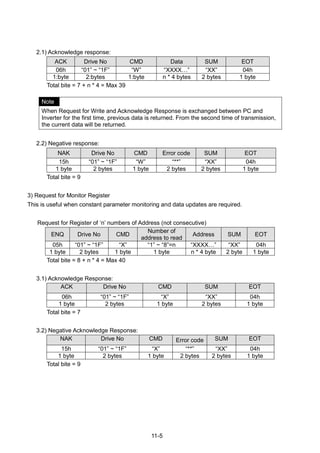
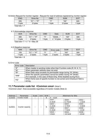
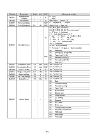
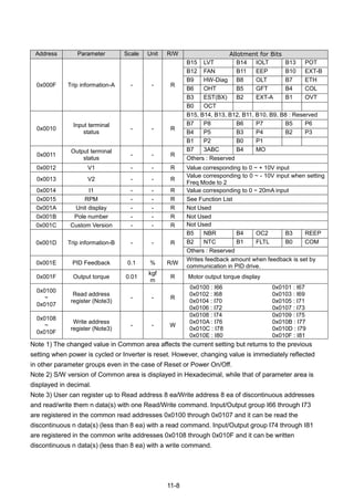
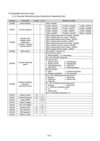
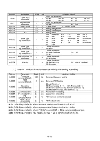
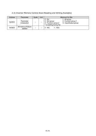
![11-12
11.8 Troubleshooting
Refer to Troubleshooting when RS-485 communication error occurs.
Check points Corrective measures
Is the power provided to the converter? Provide electric power to the converter.
Are the connections between converter and
computer correct?
Refer to converter manual.
Is Master not polling? Verify the master is polling the inverter.
Is baud rate of computer and inverter correctly
set?
Set the correct value in accordance with“11.3
Installation”.
Is the data format of user program* right? Revise User Program (Note1).
Is the connection between converter and
communication card right?
Check for GF the correct wiring in accordance
with“11.3 Installation”.
(Note 1) User program is User-made S/W for PC.
11.9 Miscellaneous
ASCII Code List
Character Hex Character Hex Character Hex Character Hex Character Hex
A
B
C
D
E
F
G
H
I
J
K
L
M
N
O
P
Q
R
S
T
U
V
W
X
Y
Z
41
42
43
44
45
46
47
48
49
4A
4B
4C
4D
4E
4F
50
51
52
53
54
55
56
57
58
59
5A
a
b
c
d
e
f
g
h
i
J
k
l
m
n
o
p
q
r
s
t
u
v
w
x
y
z
61
62
63
64
65
66
67
68
69
6A
6B
6C
6D
6E
6F
70
71
72
73
74
75
76
77
78
79
7A
0
1
2
3
4
5
6
7
8
9
space
!
"
#
$
%
&
'
(
)
*
+
,
-
.
/
30
31
32
33
34
35
36
37
38
39
20
21
22
23
24
25
26
27
28
29
2A
2B
2C
2D
2E
2F
:
;
<
=
>
?
@
[
]
{
|
}
~
BEL
BS
CAN
CR
DC1
DC2
DC3
DC4
DEL
3A
3B
3C
3D
3E
3F
40
5B
5C
5D
5E
5F
60
7B
7C
7D
7E
07
08
18
0D
11
12
13
14
7F
DLE
EM
ACK
ENQ
EOT
ESC
ETB
ETX
FF
FS
GS
HT
LF
NAK
NUL
RS
S1
SO
SOH
STX
SUB
SYN
US
VT
10
19
06
05
04
1B
17
03
0C
1C
1D
09
0A
15
00
1E
0F
0E
01
02
1A
16
1F
0B](https://image.slidesharecdn.com/ig5amanualv2-200106075958/85/I-g5a-manual_v2-4_-110131-166-320.jpg)
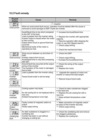
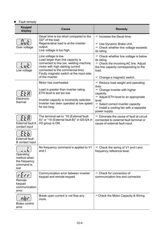
![12-5
Fault remedy
Protective functions & cause Descriptions
EEP : Parameter save error
HWT : Hardware fault
Err : Communication error
COM : Keypad error
NTC : NTC error
Contact your local LSIS sales
representative.
Overload Protection
IOLT : IOLT(inverter Overload Trip) protection is activated at 150% of the inverter rated current for 1
minute and greater.
OLT : OLT is selected when F56 is set to 1 and activated at 200% of F57[Motor rated current] for 60
sec in F58. This can be programmable.
iG5A is not provided with “Overspeed Protection.”](https://image.slidesharecdn.com/ig5amanualv2-200106075958/85/I-g5a-manual_v2-4_-110131-171-320.jpg)
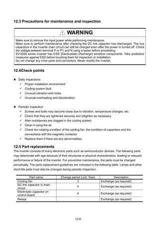
![13-1
CHAPTER 13 - SPECIFICATIONS
13.1 Technical data
Input & output ratings: Single Phase 200V Class
Input & output ratings: Three Phase 200V Class
SV ■■■iG5A –2 ■■ 004 008 015 022 037 040 055 075 110 150 185 220
Max capacity1
[HP] 0.5 1 2 3 5 5.4 7.5 10 15 20 25 30
[kW] 0.4 0.75 1.5 2.2 3.7 4.0 5.5 7.5 11 15 18.5 22
Output
ratings
Capacity [kVA] 2
0.95 1.9 3.0 4.5 6.1 6.5 9.1 12.2 17.5 22.9 28.2 33.5
FLA [A] 3
2.5 5 8 12 16 17 24 32 46 60 74 88
Max
Frequency
400 [Hz] 4
Max Voltage 3Φ 200 ~ 230V 5
Input
ratings
Rated Voltage 3Φ 200 ~ 230 VAC (+10%, -15%)
Rated
Frequency
50 ~ 60 [Hz] (5%)
Cooling method N/C6
Forced cooling
Weight [kg] 0.76 0.77 1.12 1.84 1.89 1.89 3.66 3.66 9.0 9.0 13.3 13.3
1) Indicates the maximum applicable motor capacity when using a 4-pole standard motor.
2) Rated capacity is based on 220V for 200V class and 440V for 400V class.
3) Refer to 13-4 when Carrier frequency setting (H39) is above 3kHz.
4) Max frequency setting range is extended to 300Hz when H40 (Control mode select) is set to 3
(Sensorless vector control).
5) Maximum output voltage cannot be higher than the input voltage. It can be programmable below
input voltage.
6) N/C: Natural Convention
SV ■■■iG5A –1 ■■ 004 008 015
Max capacity1
[HP] 0.5 1 2
[kW] 0.4 0.75 1.5
Output
ratings
Capacity [kVA] 2
0.95 1.9 3.0
FLA [A] 3
2.5 5 8
Max Frequency 400 [Hz] 4
Max Voltage 3Φ 200 ~ 230V 5
Input
ratings
Rated Voltage 1Φ 200 ~ 230 VAC (+10%, -15%)
Rated Frequency 50 ~ 60 [Hz] (5%)
Cooling method Forced cooling
Weight [kg] 0.77 1.12 1.84](https://image.slidesharecdn.com/ig5amanualv2-200106075958/85/I-g5a-manual_v2-4_-110131-173-320.jpg)
![13-2
Input & output ratings: Three Phase 400V Class
SV ■■■ iG5A – 4 ■■ 004 008 015 022 037 040 055 075 110 150 185 220
Max capacity
[HP] 0.5 1 2 3 5 5.4 7.5 10 15 20 25 30
[kW] 0.4 0.75 1.5 2.2 3.7 4.0 5.5 7.5 11 15 18.5 22
Output
ratings
Capacity [kVA] 2
0.95 1.9 3.0 4.5 6.1 6.9 9.1 12.2 18.3 22.9 29.7 34.3
FLA [A] 3
1.25 2.5 4 6 8 9 12 16 24 30 39 45
Max
Frequency
400 [Hz] 4
Max Voltage 3Φ 380 ~ 480V 5
Input
ratings
Rated Voltage 3Φ 380 ~ 480 VAC (+10%, -15%)
Rated
Frequency
50 ~ 60 [Hz] (5%)
Cooling method N/C Forced cooling
Weight [kg] 0.76 0.77 1.12 1.84 1.89 1.89 3.66 3.66 9.0 9.0 13.3 13.3
1) Indicates the maximum applicable motor capacity when using a 4-pole standard motor.
2) Rated capacity is based on 220V for 200V class and 440V for 400V class.
3) Refer to 13-4 when Carrier frequency setting (H39) is above 3kHz.
4) Max frequency setting range is extended to 300Hz when H40 (Control mode select) is set to 3
(Sensorless vector control).
5) Maximum output voltage cannot be higher than the input voltage. It can be programmable below
input voltage.
6) N/C: Natural Convention
Control
Control method V/F, Sensorless vector control
Frequency setting resolution
Digital command: 0.01Hz
Analog command: 0.06Hz (Max freq.: 60Hz)
Frequency accuracy
Digital command: 0.01% of Max output frequency
Analog command: 0.1% of Max output frequency
V/F pattern Linear, Squared, User V/F
Overload capacity 150% per 1 min.
Torque boost Manual/Auto torque boost
Dynamic
Braking
Max braking
torque
20% 1)
Time/%ED 150% 2) when using optional DB resistor
1) Means average braking torque during Decel to stop of a motor.
2) Refer to page 13-8 for DB resistor specification.](https://image.slidesharecdn.com/ig5amanualv2-200106075958/85/I-g5a-manual_v2-4_-110131-174-320.jpg)
![13-3
Operation
Operation mode
Keypad/ Terminal/ Communication option/ Remote keypad
selectable
Frequency setting
Analog: 0 ~ 10[V], -10 ~ 10[V], 0 ~ 20[mA]
Digital: Keypad
Operation features PID, Up-down, 3-wire
Input
Multi-function terminal
P1 ~ P8
NPN / PNP selectable (See page 2-13)
FWD/REV RUN, Emergency stop, Fault reset,
Jog operation, Multi-step Frequency-High, Mid, Low, Multi-step
Accel/Decel-High, Mid, Low, DC braking at stop, 2nd
motor
select, Frequency UP/Down, 3-wire operation, External trip A, B,
PID-Inverter (v/f) operation bypass, Option-inverter (v/f)
operation bypass, 2nd
Source, Analog Hold, Accel/Decel stop,
Up/Down Save Freq, Jog FX/RX
Output
Open collector terminal
Fault output and
inverter status output
Less than DC 24V 50mA
Multi-function relay
(N.O., N.C.) Less than AC250V 1A,
Less than DC 30V 1A
Analog output
0 ~ 10 Vdc (less than10mA): Output Freq, Output Current,
Output Voltage, DC link selectable
Protective function
Trip
Over Voltage, Under Voltage, Over Current, Over Current 2, Ground Fault current
detection, Inverter Overheat, Motor Overheat, Output Phase Open, Overload
Protection, Communication Error, Loss of Speed Command, Hardware Fault, Fan trip,
Brake error.
Alarm Stall prevention, overload
Momentary
Power
Loss1)
Below 15 msec: Continuous operation (should be within rated input voltage, rated
output power.)
Above 15 msec: Auto restart enable
1) Single Phase products: Continuous operation (should be within rated input voltage, rated output
power)
Environment
Protection
degree
IP 20, UL TYPE1 (Ambient Temperature 40 C) 2)
Ambient temp -10C ~ 50C
Storage temp -20C ~ 65C
Humidity Below 90% RH (no condensation)
Altitude/Vibration Below 1,000m, 5.9m/sec2
(0.6G)
Atmospheric
pressure
70~106 kPa
Location Protected from corrosive gas, combustible gas, oil mist or dust
2) UL TYPE1 with top cover and conduit box installed.](https://image.slidesharecdn.com/ig5amanualv2-200106075958/85/I-g5a-manual_v2-4_-110131-175-320.jpg)
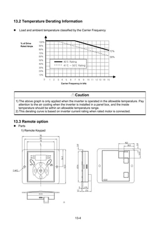
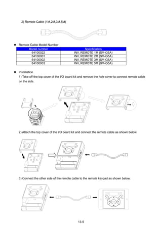
![13-7
Conduit Kit
Conduit Kit Model
Inverter Conduit Kit 1 SV004IG5A-2/4, SV008IG5A-2/4, SV004IG5A-1
Inverter Conduit Kit 2 SV015IG5A-2/4, SV008IG5A-1
Inverter Conduit Kit 3
SV022IG5A-2/4, SV037IG5A-2/4, SV040IG5A-2/4,
SV015IG5A-1
Inverter Conduit Kit 4 SV055IG5A-2/4, SV075IG5A-2/4
Inverter Conduit Kit 5 SV110IG5A-2/4, SV150IG5A-2/4
Inverter Conduit Kit 6 SV185IG5A-2/4, SV220IG5A-2/4
13.5 Braking resistor
Input
Voltage
Inverter capacity
[kW]
100 % braking 150% braking
[] [W]* [] [W]*
200V 0.4 400 50 300 100
0.75 200 100 150 150
1.5 100 200 60 300
2.2 60 300 50 400
3.7 40 500 33 600
5.5 30 700 20 800
7.5 20 1000 15 1200
11.0 15 1400 10 2400
15.0 11 2000 8 2400
18.5 9 2400 5 3600
22.0 8 2800 5 3600
400V 0.4 1800 50 1200 100
0.75 900 100 600 150
1.5 450 200 300 300
2.2 300 300 200 400
3.7 200 500 130 600
5.5 120 700 85 1000
7.5 90 1000 60 1200
11.0 60 1400 40 2000
15.0 45 2000 30 2400
18.5 35 2400 20 3600
22.0 30 2800 20 3600
* The wattage is based on Enable duty (%ED) 5% with continuous braking time 15 sec.](https://image.slidesharecdn.com/ig5amanualv2-200106075958/85/I-g5a-manual_v2-4_-110131-179-320.jpg)