This document is a user manual for OMRON's SMARTSTEP A-series servomotors (models R7M-A@) and servo drivers (models R7D-AP@). It provides warnings and precautions for safely installing, operating, and maintaining the products. The manual describes the components, specifications, functions, wiring, parameter settings, troubleshooting, and other instructions to ensure proper use of the servomotors and servo drivers.


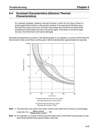
![Chapter 3
3-37
System Design and Installation
3-3 Regenerative Energy Absorption
The Servo Drivers have internal regenerative energy absorption circuitry for absorbing
the regenerative energy produced during time such as Servomotor deceleration, and
thus preventing the DC voltage from increasing. An overvoltage error is generated,
however, if the amount of regenerative energy from the Servomotor is too large. If this
occurs, measures must be taken to reduce the regenerative energy produced by
changing operating patterns, and so on, or to improve the regenerative energy
absorption capacity by connecting external regeneration resistance.
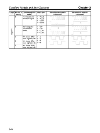
3-3-1 Regenerative Energy Calculation
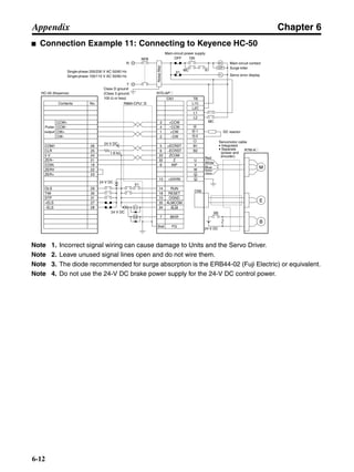
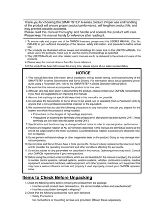
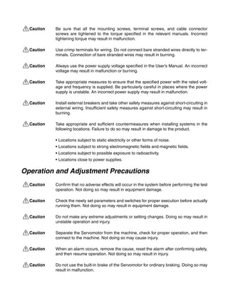
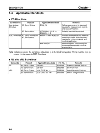
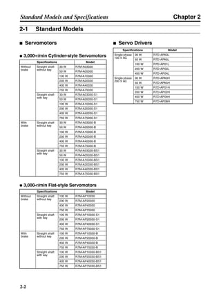
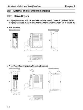
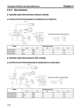
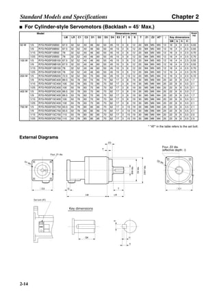
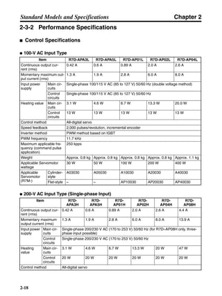
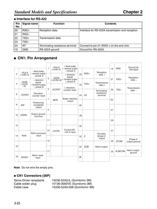
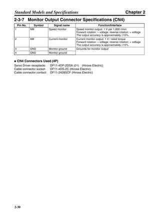
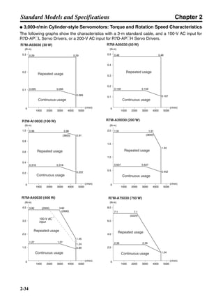
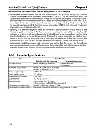
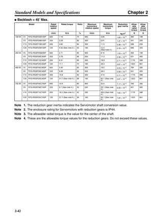
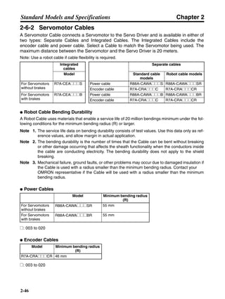
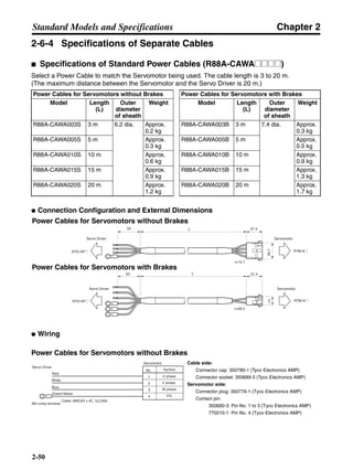
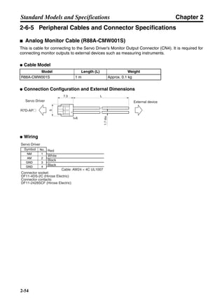
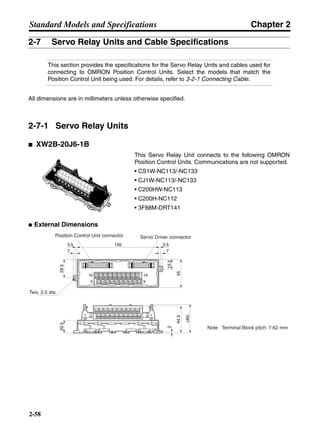
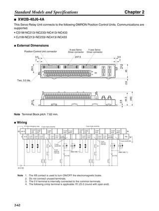
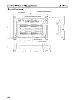
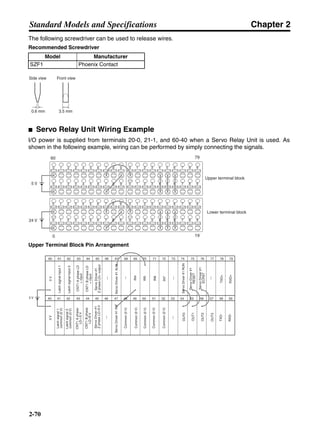
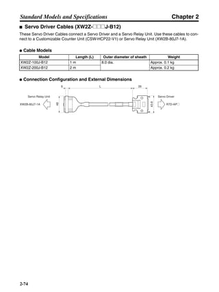
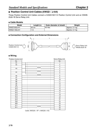
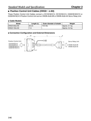
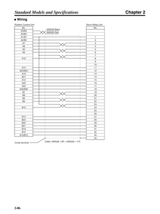
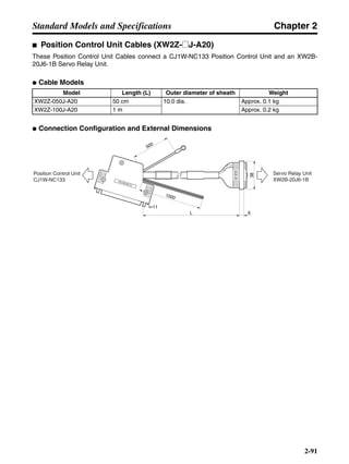
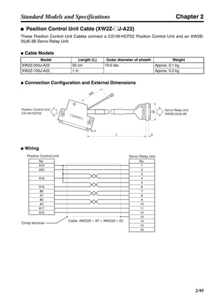
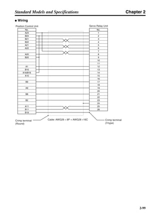
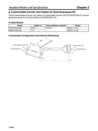
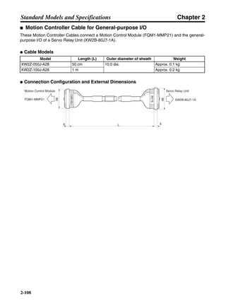
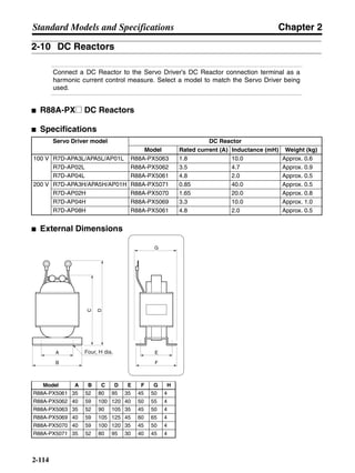
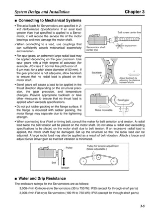
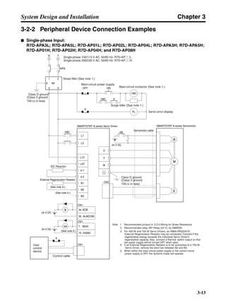
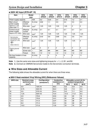
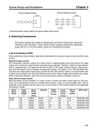
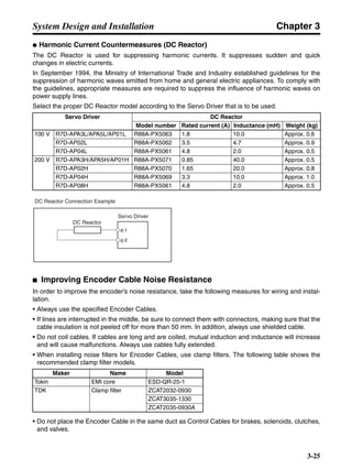
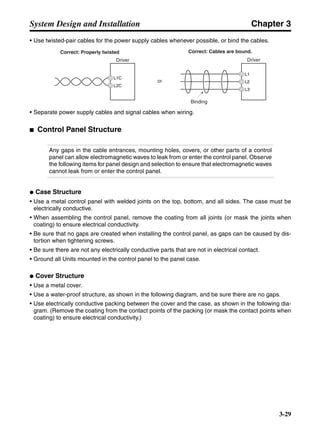
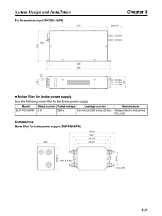
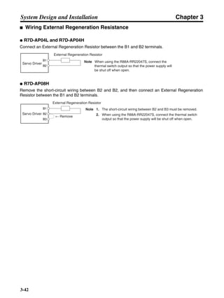
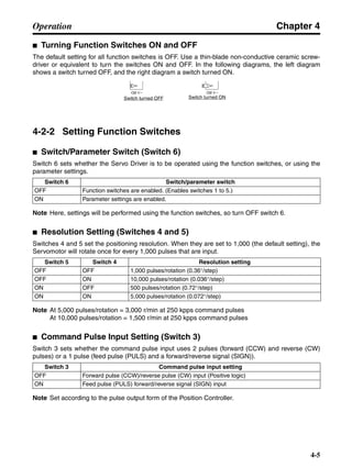
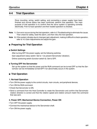
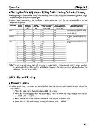
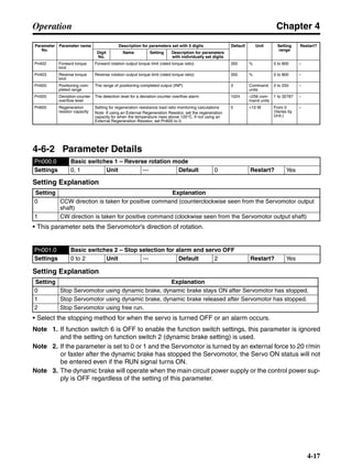
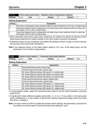
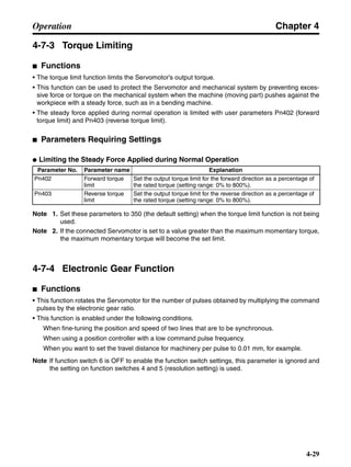
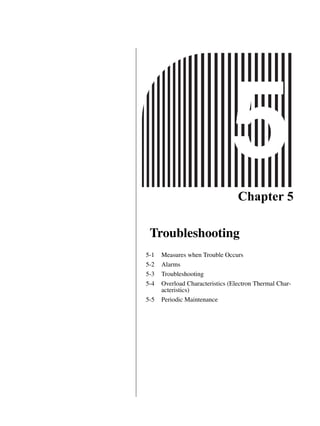
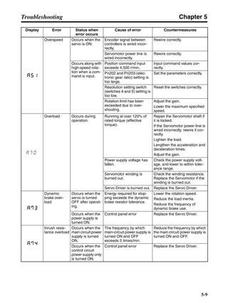
■ Horizontal Axis
Note In the output torque graph, acceleration in the positive direction is shown as positive, and
acceleration in the negative direction is shown as negative.
• The regenerative energy values for Eg1 and Eg2 are derived from the following equations.
Servomotor operation
Servomotor output torque
+N1
−N2
TD1
TD2
t1 t2
T
Eg1
Eg2
N1, N2: Rotation speed at beginning of deceleration [r/min]
TD1, TD2: Deceleration torque [N·m]
t1, t2: Deceleration time [s]
• Eg1 = • • N1 • TD1 • t1 [J] = 0.0524 • N1 • TD1 • t1 [J]
2 60
60
2π
2π
1
• Eg2 = • • N2 • TD2 • t2 [J] = 0.0524 • N2 • TD2 • t2 [J]
2
1](https://image.slidesharecdn.com/datasheetr7ma10030s1-151021112310-lva1-app6892/85/Datasheet-r7-m-a10030_s1-177-320.jpg)
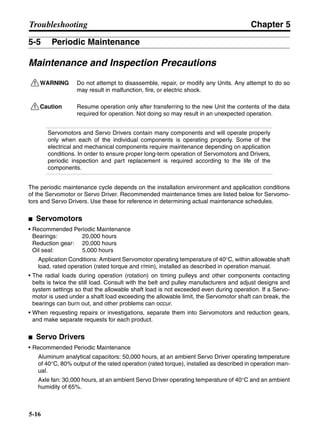
![Chapter 3
3-38
System Design and Installation
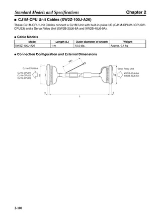
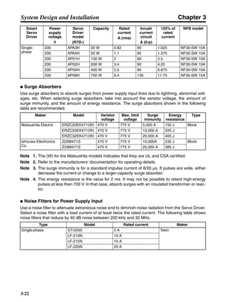
Note There is some loss due to winding resistance, so the actual regenerative energy will be approx-
imately 90% of the values derived from these equations.
• For Servo Driver models with internal capacitors for absorbing regenerative energy (i.e., models of
400 W or less.), the values for both Eg1 or Eg2 (unit: J) must be lower than the Servo Driver’s
regenerative energy absorption capacity. (The capacity varies depending on the model. For details,
refer to 3-3-2 Servo Driver Regenerative Energy Absorption Capacity.)
• For Servo Driver models with internal regeneration resistance for absorbing regenerative energy
(i.e., models of 750 W), the average amount of regeneration Pr (unit: W) must be calculated, and
this value must be lower than the Servo Driver’s regenerative energy absorption capacity. (For
details, refer to 3-3-2 Servo Driver Regenerative Energy Absorption Capacity.)
The average amount of regeneration (Pr) is the power consumed by regeneration resistance in
one cycle of operation.
Pr = (Eg1 + Eg2)/T [W]
T: Operation cycle [s]
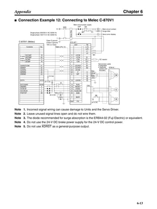
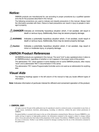
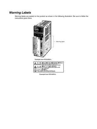
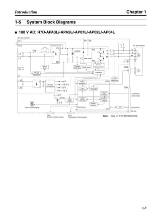
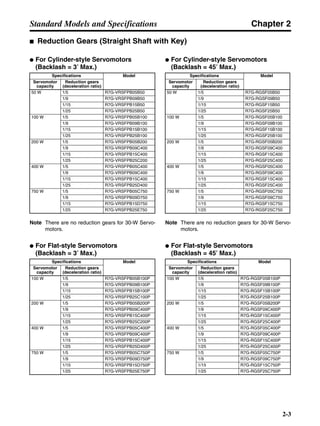
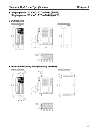
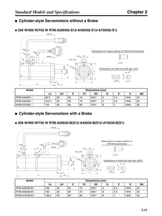
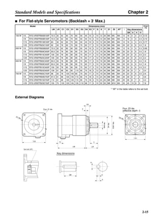
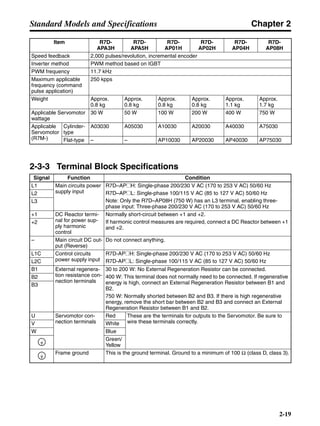
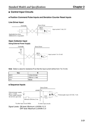
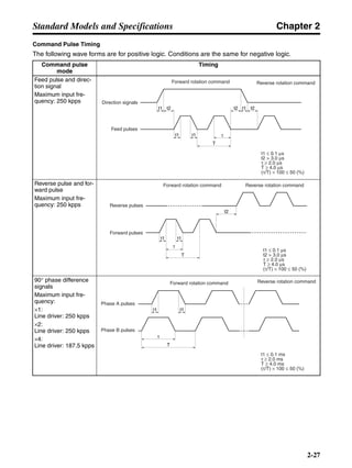
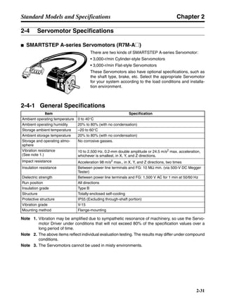
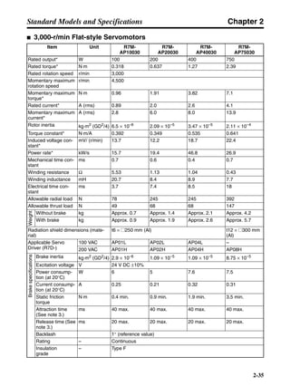
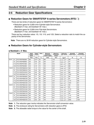
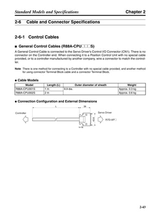
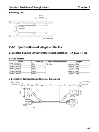
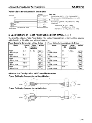
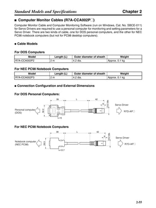
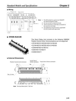
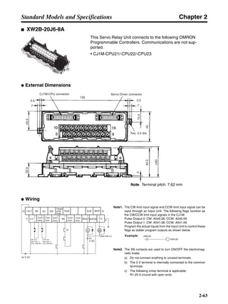
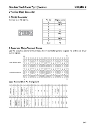
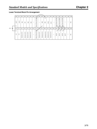
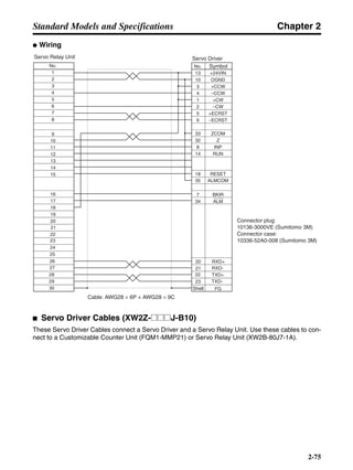
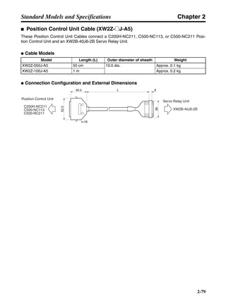
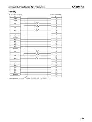
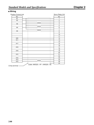
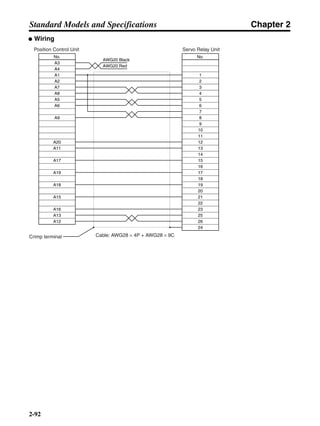
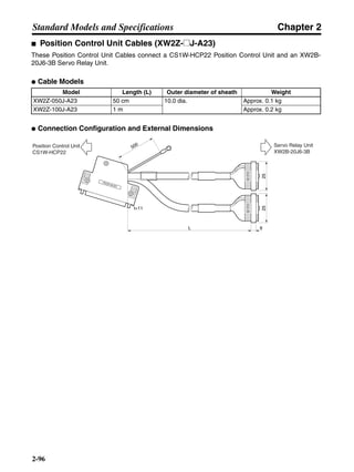
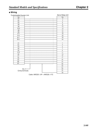
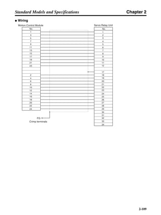
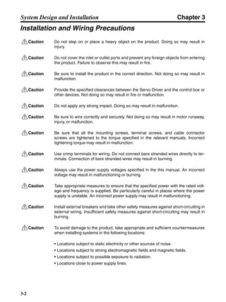
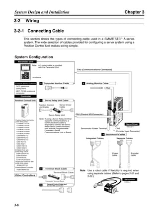
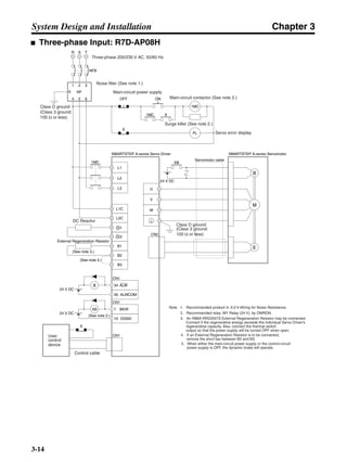
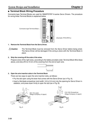
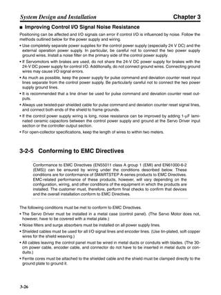
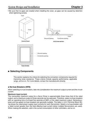
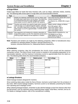
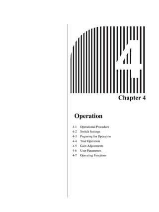
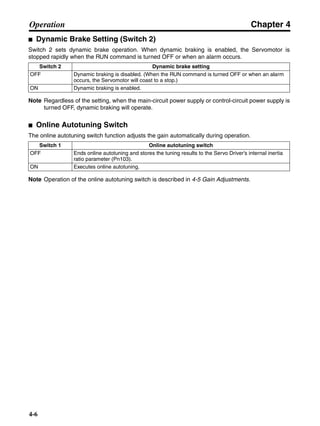
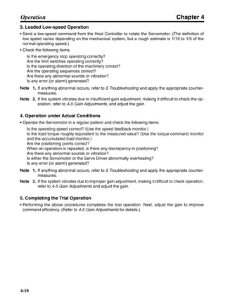
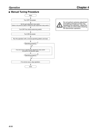
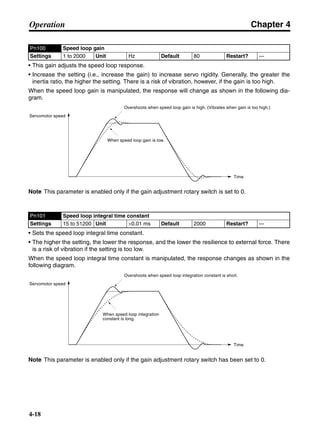
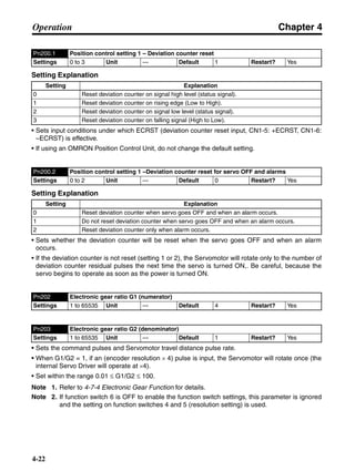
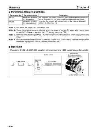
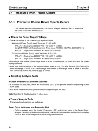
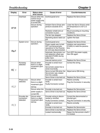
■ Vertical Axis
Note In the output torque graph, acceleration in the positive direction (rise) is shown as positive, and
acceleration in the negative direction (fall) is shown as negative.
• The regenerative energy values for Eg1, Eg2, and Eg3 are derived from the following equations.
Fall
Rise
Servomotor operation
Servomotor output torque
+N1
−N2
t1 t2 t3
T
Eg1
Eg3Eg3
TD2
TL2
TD1
Eg2](https://image.slidesharecdn.com/datasheetr7ma10030s1-151021112310-lva1-app6892/85/Datasheet-r7-m-a10030_s1-178-320.jpg)
![Chapter 3
3-39
System Design and Installation
Note There is some loss due to winding resistance, so the actual regenerative energy will be approx-
imately 90% of the values derived from these equations.
• For Servo Driver models with internal capacitors for absorbing regenerative energy (i.e., models of
400 W or less.), the values for both Eg1 or [Eg2+Eg3] (unit: J) must be lower than the Servo Driver’s
regenerative energy absorption capacity. (For details, refer to 3-3-2 Servo Driver Regenerative
Energy Absorption Capacity.)
• For Servo Driver models with internal regeneration resistance for absorbing regenerative energy
(i.e., models of 750 W), the average amount of regeneration Pr (unit: W) must be calculated, and
this value must be lower than the Servo Driver’s regenerative energy absorption capacity. (For
details, refer to 3-3-2 Servo Driver Regenerative Energy Absorption Capacity.)
The average amount of regeneration (Pr) is the power consumed by regeneration resistance in
one cycle of operation.
Pr = (Eg1 + Eg2+ Eg3)/T [W]
T: Operation cycle [s]
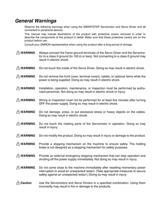
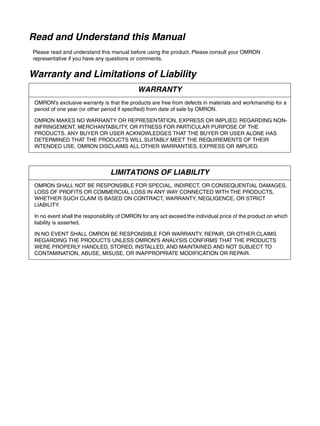
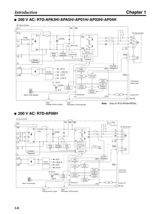
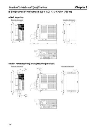
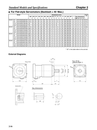
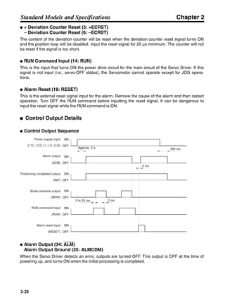
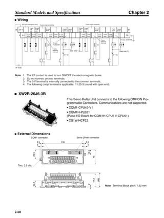
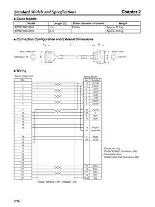
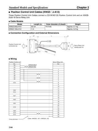
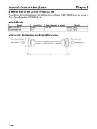
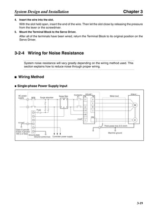
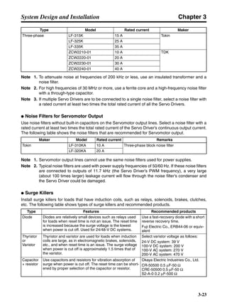
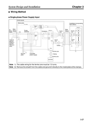
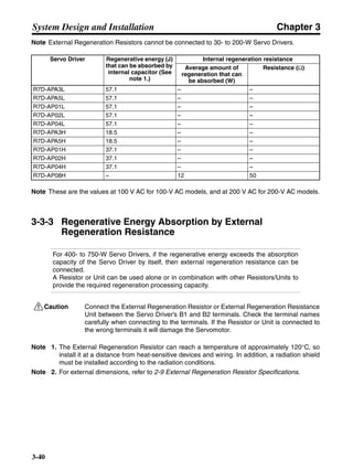
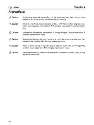
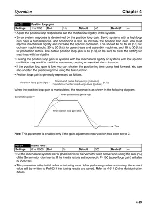
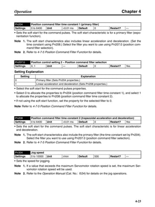
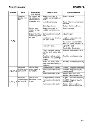
3-3-2 Servo Driver Regenerative Energy Absorption Capacity
■ Amount of Internal Regeneration Resistance in Servo Drivers
SMARTSTEP A-series Servo Drivers absorb regenerative energy by means of internal capacitors or
resistors. If the regenerative energy is more than can be processed internally, an overvoltage error is
generated and operation cannot continue. The following table shows the regenerative energy (and
amount of regeneration) that the individual Servo Drivers themselves can absorb. If these values are
exceeded, take the following measures.
• Connect external regeneration resistance (to improve the regeneration processing capacity).
• Reduce the operating rotation speed. (The amount of regeneration is proportional to the square of
the rotation speed.)
• Lengthen the deceleration time (to decrease the regenerative energy produced per time unit).
• Lengthen the operation cycle, i.e., the cycle time (to decrease the average regenerative power).
N1, N2: Rotation speed at beginning of deceleration [r/min]
TD1, TD2: Deceleration torque [N·m]
TL2: Torque when falling [N·m]
t1, t3: Deceleration time [s]
t2: Constant-velocity travel time when falling [s]
• Eg1 = • • N1 • TD1 • t1 [J] = 0.0524 • N1 • TD1 • t1 [J]
2 60
60
2π
2π
1
• Eg2 = • N2 • TL2 • t2 [J] = 0.105 • N2 • TL2 • t2 [J]
60
2π
• Eg3 = • • N2 • TD2 • t3 [J] = 0.0524 • N2 • TD2 • t3 [J]
2
1](https://image.slidesharecdn.com/datasheetr7ma10030s1-151021112310-lva1-app6892/85/Datasheet-r7-m-a10030_s1-179-320.jpg)


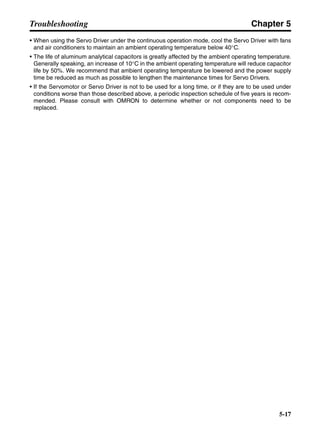


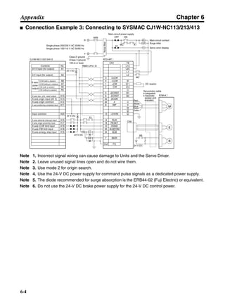


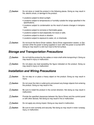
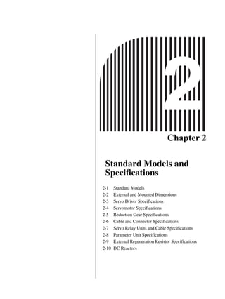
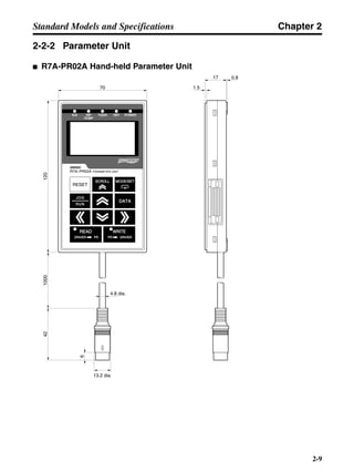
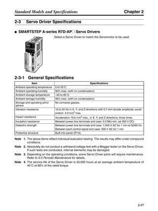
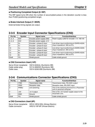
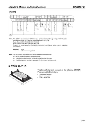
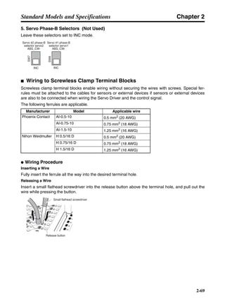
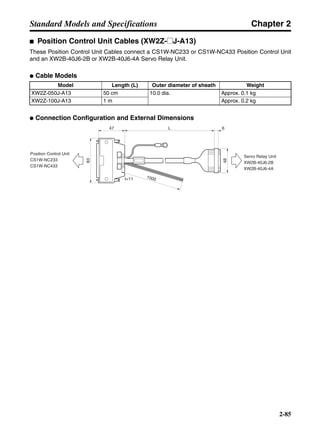
![Chapter 6
6-11
Appendix
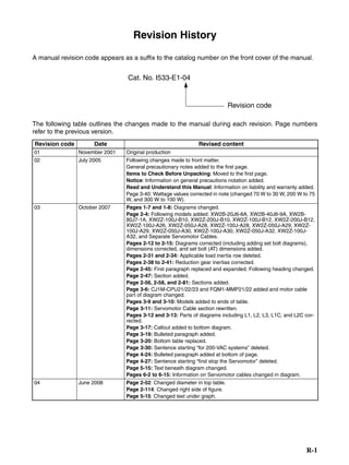
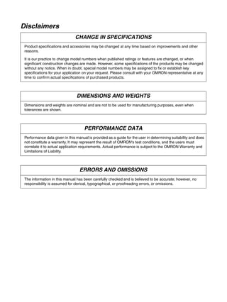
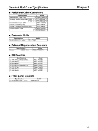
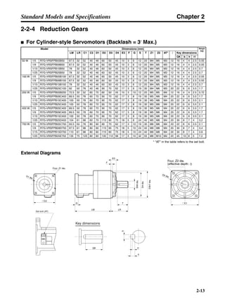
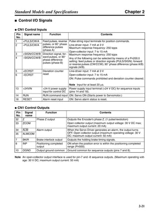
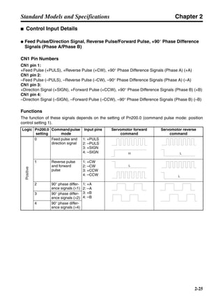
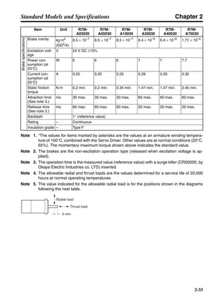
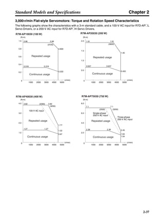
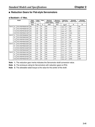
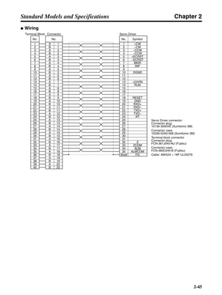
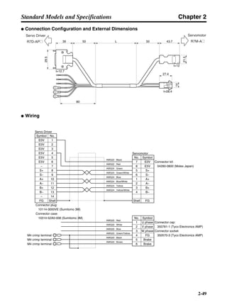
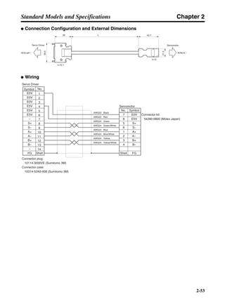
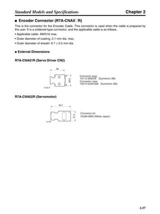
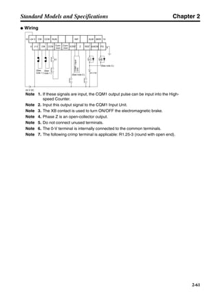
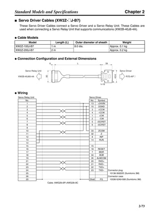
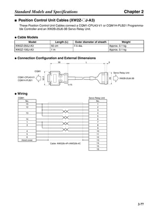
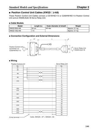
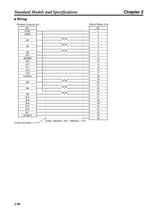
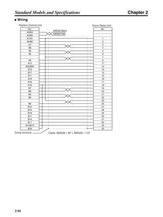
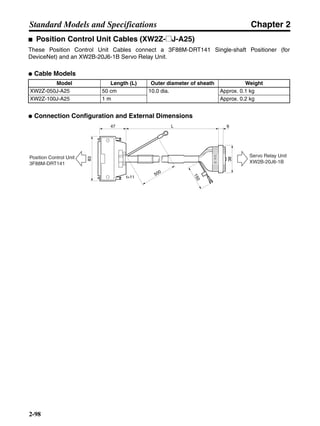
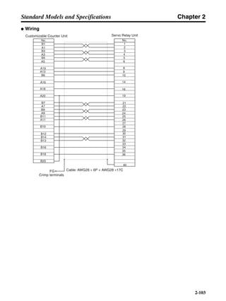
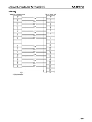
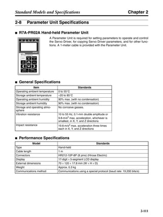
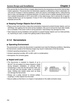
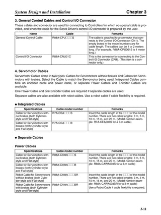
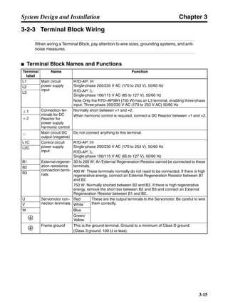
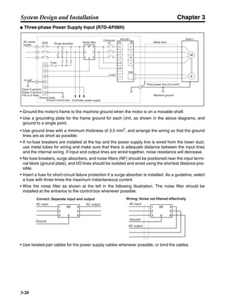
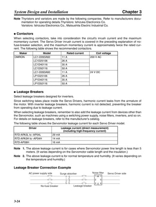
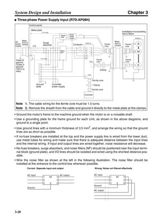
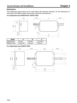
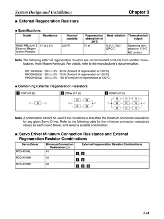
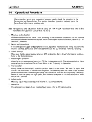
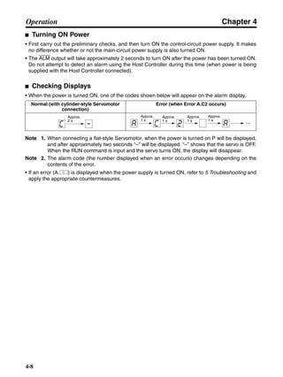
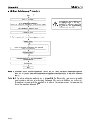
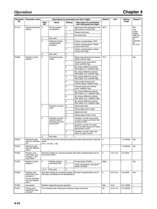
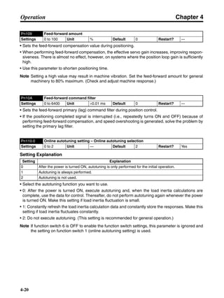
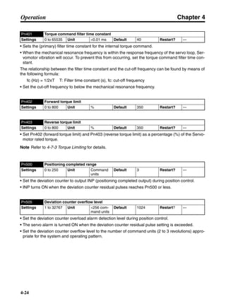
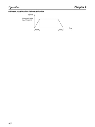
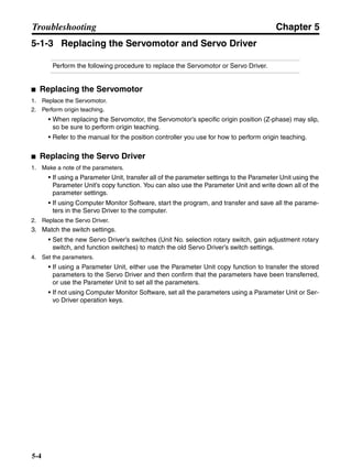
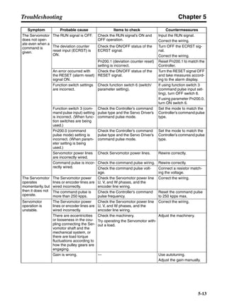
■ Connection Example 10: Connecting to Oriental SG8030J
Note 1. Incorrect signal wiring can cause damage to Units and the Servo Driver.
Note 2. Leave unused signal lines open and do not wire them.
Note 3. The diode recommended for surge absorption is the ERB44-02 (Fuji Electric) or equivalent.
Note 4. Do not use the 24-V DC brake power supply for the 24-V DC control power.
SG8030J (Oriental) R7D-AP@
R7M-A@
Contents No.
CN1 TB
+24V 3
GND
CCW pulse/rotation direction
CW pulse/pulse
Operation mode switching
HOMELS
Start
M0 [CW scan]
M1 [CCW scan]
Emergency stop
2
4
1
2
5
6
33
32
8
13
14
18
10
35
34
7
Shell
3 +CCW
L1C
L2C
L1
L2
B1
B2
U
V
W
1
2
−CCW
+CW
−CW
+ECRST
−ECRST
ZCOM
INP
+24VIN
RUN
RESET
OGND
ALMCOM
ALM
FG
Z
8
7
1
5
6
10
11
9
CN2
M
E
X1
XB
24 V DC
Red
White
Blue
Green/
Yellow
Noisefilter
R
T
Single-phase 200/230 V AC 50/60 Hz
Single-phase 100/115 V AC 50/60 Hz
MC
MC
SUP
NFB ONOFF
X1
X1MC
Main-circuit power supply
Main-circuit contact
Servo error display
Surge killer
X1
24 V DC
DC reactor
PL
B
24 V DC
XB
BKIR
R88A-CPU@S
Class D ground
(Class 3 ground:
100 Ω or less)
+
+
+
− Servomotor cable
• Integrated
• Separate
(power and
encoder)](https://image.slidesharecdn.com/datasheetr7ma10030s1-151021112310-lva1-app6892/85/Datasheet-r7-m-a10030_s1-243-320.jpg)