Download as PDF, PPTX


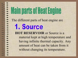
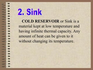


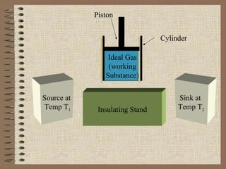
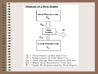
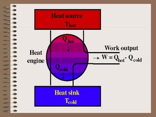
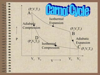
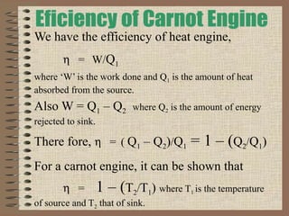


The document explains the concept of a heat engine, which converts heat into work through a cyclic process involving a hot reservoir, cold reservoir, and a working substance. It details the Carnot engine and its maximum efficiency derived from the Carnot cycle, which includes four thermodynamic processes: isothermal expansion and compression, as well as adiabatic expansion and compression. The efficiency formula is provided, showing that a real engine's efficiency cannot exceed that of the ideal Carnot engine operating between the same temperature limits.