ISO/FDIS 20519
•Download as PPTX, PDF•
1 like•668 views

This document provides a 3-sentence summary of the key details from the ISO/FDIS 20519 document: The ISO/FDIS 20519 document establishes international standards for bunkering liquefied natural gas (LNG) fuelled vessels. It includes requirements for transfer systems, operational procedures, personnel training, documentation, and risk assessments. Adherence to the standards aims to ensure LNG bunkering operations can be conducted safely and sustainably for all stakeholders involved.

Recommended
More Related Content
What's hot
What's hot (20)
Similar to ISO/FDIS 20519
Similar to ISO/FDIS 20519 (20)
More from Abhishek Rajvanshi
Recently uploaded
Recently uploaded (20)
ISO/FDIS 20519
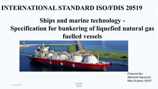
- 1. INTERNATIONAL STANDARD ISO/FDIS 20519 25 July 2017 ISO/FDIS 20519 1 Ships and marine technology - Specification for bunkering of liquefied natural gas fuelled vessels Prepared By:- Abhishek Rajvanshi, Mba Student, RGIPT
- 2. Contents • Introduction about ISO / FDIS 20519 • Brief about LNG bunkering . • Transfer system design requirements. • LNG bunkering processes and procedures. • Personnel training. • Records and documentation. • Risk assessment and controlled zones. 25 July 2017 ISO/FDIS 20519 2
- 3. Introduction about ISO/ FDIS 20519 • To standardise LNG bunkering operations for all stakeholders at the international level a new ISO standard is set up to ensure LNG-fuelled vessels can bunker in a safe and sustainable way. It is published on 13th Feb, 2017. • It will help operators select vessel fuel providers that meet defined safety and fuel standards. • ISO 20519 contains requirements that are not covered by the IGC Code, the prevailing international code for the safe carriage by sea of liquefied gases in bulk. It includes the following items: • Hardware: liquid and vapour transfer systems • Operational procedures • Requirement for the LNG provider to provide an LNG bunker delivery note • Training and qualifications of personnel involved • Requirements for LNG facilities to meet applicable ISO standards and local codes 25 July 2017 ISO/FDIS 20519 3
- 4. Brief about LNG Bunkering. • LNG Bunkering is a particular type of operation where LNG fuel is transferred from a given distribution source to a LNG fuelled ship. It involves the participation of different stakeholders, from the ship-side, LNG supplier, ports, safety personnel, administrations and policy makers. • The main challenge with LNG Bunkering is the interfaces created during LNG delivery moment. These challenges can be either of a regulatory or technical nature. LNG Bunkering methods • LNG Vessel Bunkering. • LNG ship to ship bunkering. • LNG terminal to ship bunkering . • LNG truck to ship bunkering 25 July 2017 ISO/FDIS 20519 4
- 5. Transfer system design requirements. • Vessel requirements It applies to vessels of all sizes, in domestic or international service. Bunkering vessels shall conform with this document and be approved by its Flag State, Recognized Organization or Classification Society that complies with the applicable uniform interpretations and requirements posted by IACS, indicating that it meets, at a minimum, the applicable requirements of the IGC Code, this document and applicable Flag State requirements. Receiving vessels shall conform with this document and be approved by its Flag State, Recognized Organization or Classification Society that complies with the applicable uniform interpretations and requirements posted by IACS, indicating that it meets, at a minimum, the applicable requirements of the IGF Code, this document and applicable Flag State requirements . • Facility requirements Mobile facilities(e.g. tank trucks, rail cars & portable tanks)including tanks, piping, hoses , pumps and values shall also be fabricated & conform to meet ISO or other standard recognized by national standard bodies. The bunkering terminal also conform to local codes. If local codes do not address then the terminal operator shall obtain a document issued by a competent organization. 25 July 2017 ISO/FDIS 20519 5
- 6. Transfer system design requirements. • Transfer equipment requirements All equipment used in the transfer system shall meet the requirements defined for that specific piece of equipment. The use of liquid nitrogen as a substitute for LNG during testing of the equipment by the equipment manufacturers is acceptable. All the components of the transfer system through which LNG or natural gas flow shall be rated for the maximum transfer system design pressure but shall have a pressure rating of no less than 1,034 MPa. All flanges shall be at least Class 150 in accordance with ASME B16.5 and of the weld-neck type. Flow rate of LNG through the transfer system shall not exceed 12 m/s, however, higher speeds can be locally acceptable in reduced passages, for example in the ERS, provided cavitation and vibration is acceptable 25 July 2017 ISO/FDIS 20519 6
- 7. Transfer system design requirements. • All the components of the transfer system shall be fabricated to meet or exceed the applicable sections of the standards indicated in Table 1, the IGC/IGF Codes, in addition to other requirements listed in this document. • 25 July 2017 ISO/FDIS 20519 7
- 8. Transfer system design requirements. • Emergency shutdown and release systems The LNG transfer system shall be fitted with an emergency release system (ERS) and connected to an emergency shutdown system (ESD). The delivery facility and receiving vessel ESD systems shall be interconnected with a ship/shore or ship/ship ESD link to ensure the coordinated operation of both the delivery and receiving ESD systems and ERS. The ERS shall be designed to protect the transfer system and the connections by disconnecting the transfer system, primarily should the vessel drift out of their operating envelope. The ERS shall consist of an emergency release coupling (ERC)/including interlocked isolating valves to minimize loss of LNG or NG when the ERC is activated. The ESD shall be designed to be activated by operator-initiated signals as well as sensor input and when activated, initiate shutting down the LNG transfer pumps and closing of the ESD valves. 25 July 2017 ISO/FDIS 20519 8
- 9. Transfer system design requirements. • Emergency Shutdown (ESD) Having a means to quickly and safely shut down the bunkering operation by closing the manifold valves, stopping pumps, and closing tank filling valves is essential to ensure safety. The ESD should be capable of activation from both the bunker receiving ship and the bunker supplier, and the signal should simultaneously activate the ESD on both sides of the transfer operation. No release of gas or liquid shall take place as a result of ESD activation. Typical reasons for activation of the ESD include the following: Gas detection Fire detection Manual activation from either the supplier or receiver Excessive ship movement Power failure High level in receiving tank Abnormal pressure in transfer system High tank pressure Other causes as determined by system designers and regulatory organizations 25 July 2017 ISO/FDIS 20519 9
- 10. Transfer system design requirements.. • Identification of transfer equipment The LNG bunker provider shall list the equipment and applicable operating parameters for the equipment that will be used during a bunkering operation including, if applicable, the return of natural gas (vapour return). This list shall at a minimum provide the following information: a) connection types to which connection is possible; b) diameter of hoses or pipes to be used; c) ESD system or systems to be used; d) maximum and minimum flow rates created by pumps or pressure differentials; e) maximum pressure the transfer system could experience during transfer or in the event the breakaway emergency release system is triggered (the valve instantly closes, i.e. surge); f) number of bunkering operations which can conduct simultaneously; g) equipment used, if any, for returning natural gas (i.e. vapour return); h) horizontal and vertical distances that their system can transfer LNG; i) weather conditions under which operation can take place including temperature, wind, precipitation, lighting; j) limitations on sea state conditions under which operations can take place; k) operating envelope of the transfer system taking into account the degrees of freedom, relative motion required in regard to h), i) and j); l) lines for inerting the system If the LNG provider has more than one type or size of transfer system or more than one pumping system, the information required by this sub clause shall be listed separately for each system. 25 July 2017 ISO/FDIS 20519 10
- 11. LNG bunkering processes and procedures • Mooring Master(s) is responsible to ensure that the vessel is/are securely moored in accordance with agreed/approved mooring plans . Mooring arrangements should take into account — wind, current/tides, waves/swell, surges from passing vessels, ice, and changes in draught, trim or list. • Communication in preparation for a transfer Prior to any connections being made in preparation of an LNG bunkering operation, these information from LNG provider shall provide to the operator of the vessel being bunkered (in written or electronic form). a) saturation pressure of the LNG being bunkered; b) how net quantity delivered will be metered and calculated; c) any restrictions on bunkering operations that were identified in the risk assessment d) location, if any, of LNG bunkering areas designated by the port or competent authority; e) if no location has been designated by a port or competent authority, the LNG provider shall provide evidence that the port or competent authority has approved the proposed location of the bunkering operation, unless the bunkering operations will take place outside of national waters. Continued….. 25 July 2017 ISO/FDIS 20519 11
- 12. LNG bunkering processes and procedures continued…. f) any restrictions imposed by the port or competent authority applicable to LNG bunkering operations; g) the transfer equipment that will be used including connection type, diameter of hoses or pipes, ESD system and any transfer system limitations in regard to sea states, distance, height or flow rates Information that the operator of the vessel to be bunkered shall provide to the LNG provider a) a description of other operations that will be taking place (including LNG and fuel oil bunkering, delivery of stores/lubes, cargo and passenger operation) and that existing procedures permit these operations simultaneously; b) any restrictions on bunkering operations that were identified in the risk assessment; c) available capacity of the LNG bunker tanks and amount of LNG being requested; d) temperature and pressure of the LNG bunker tanks; e) a statement that current conditions are within acceptable parameters of the risk assessment . f) the parameters under which their transfer system/equipment is capable of operating safely; g) connection types to which they can connect; h) diameter of hoses or pipes they can accept; i) ESD systems to which they can connect. j) maximum and minimum pump/flow rates they can accept; Continued…. 25 July 2017 ISO/FDIS 20519 12
- 13. LNG bunkering processes and procedures continued…. k)horizontal and vertical distances involved in transferring LNG to the vessel; l) weather conditions under which they can conduct a transfer including temperature, wind, precipitation, lighting; m) sea states limitations and conditions under which they can conduct a transfer . Risk Assesments General A risk assessment shall be conducted and documented before a bunkering operation is conducted at a specific location. The risk assessment shall be conducted by or on behalf of the organization providing the LNG, or the national or local authorities that have jurisdiction over the safety and security where the bunkering operation takes place • Conditions required a) proximity of the bunkering location to areas where personnel, other workers, individuals and/or the public can be expected; b) proximity of the bunkering location to port infrastructure; c) marine traffic that could impact bunkering operations; d) expected sea states, tide changes, currents and weather conditions at the bunkering location; e) any hot work within the monitoring zone; acceptability and/or limitations on conducting other simultaneous operations (SIMOPS), 25 July 2017 ISO/FDIS 20519 13
- 14. LNG bunkering processes and procedures Transfer procedures a) LNG bunker operation shall be conducted in accordance with the detailed fuel handling manual and the emergency producers specified in 18.2.3 of the IGF Code that have been approved for the involved vessel or vessels by their Flag State or other competent authority. b) For each bunkering operation, a qualified person in charge (PIC) for the receiving vessel and a person in charge for the LNG provider shall be assigned. c) On the vessel being bunkered, there shall be a dedicated manifold watch via CCTV that is able to communicate with the PIC and will monitor the transfer system for unsafe conditions. d) The LNG provider shall be a dedicated hose watch via CCTV that is able to communicate with the PIC and will monitor the transfer system for unsafe conditions. e) Planned operations checklist shall be completed within 48 h of the planned bunkering operation . f) The two PICs shall decide and agree who will make the manifold connections for receiving and delivering LNG and ensure the connections are secured and leak tested. g) Unless other arrangements are made, the bunker transfer equipment shall be supplied and maintained by the LNG provider. Continued.. 25 July 2017 ISO/FDIS 20519 14
- 15. LNG bunkering processes and procedures h) Communications for the transfer to be conducted shall meet the following requirements. h1)Communication shall be conducted in English or a language agreed upon during the pre-transfer conference. h2)Electronic devices used for communications shall be of a type approved by the competent authority; both parties shall agree on the channel they will use exclusively during the transfer and will conduct no other operations on that channel i) Pre-transfer conference shall be conducted before the transfer begins and the bunker checklists shall be signed and retained by both parties. j) The transfer system between the last shut-off valves of the LNG provider and those of the vessel being bunkered shall be drained and purged without releasing the LNG or natural gas to the atmosphere when the bunkering operation ends. k) Personnel protective equipment required should be wear by Personnel with assigned duties . l) Post-transfer conference shall be conducted upon completion of transfer operations and the bunker checklists shall be signed and retained by both parties . 25 July 2017 ISO/FDIS 20519 15
- 16. Personnel training Personnel with assigned duties related to bunkering operations onboard a vessel shall also be trained on the following: a)all applicable requirements of this document and the procedures and documents developed by the vessel operators to conform with the requirements of this document; b)appropriate equipment specific familiarization with arrangements, procedures and operational characteristics that are relevant to their routine and emergency duties; c)actions to be taken and notifications to be made in the event that the LNG transfer procedures are not being followed or a dangerous situation has been observed. Personnel providing LNG from port or mobile facilities training personnel that will be conducting LNG bunkering operations from LNG bunkering terminals or mobile LNGN facilities to be trained in accordance with local regulations and industry standards and all applicable requirements of this document and the procedures and documents developed by the vessel operators to conform with the requirements of this document. Documentation of training Organizations desiring to comply with this document shall maintain records that document that their personnel are current with the training requirements listed in this clause as applicable. This document shall list the personnel and the dates they received this training. Refresher training on the requirements of this document shall be repeated every 5 years. 25 July 2017 ISO/FDIS 20519 16
- 17. Records and documentation The following records and documents shall be maintained by parties that comply with this document: a) The transfer system analysis . b) Documentation from a Flag State, Recognized Organization or Class Society indicating the vessels involved and equipment or procedures subject to their approval comply with applicable rules . c)Documentation indicating port facilities, vehicles or portable tanks (if any) are in compliance with the requirements of this document. d) A listing of maintenance and inspections for equipment recommended or required by the equipment manufacturers’ of the equipment listed in and a record for at least the last 36 months of inspections or maintenance performed on this equipment. e) Copies (electronic or hard copy) of all completed checklists for at least the past 12 months. f) Training records (electronic or hard copy) as required in 8.2 shall be maintained for at least 5 years. These records shall identify the contents of the training received, names of people receiving the training, date of training, method of training (e.g. classroom, online or supervised on-the-job training), date of training and how satisfactory performance was evaluated g) Copies of risk assessment. Continued.. 25 July 2017 ISO/FDIS 20519 17
- 18. Records and documentation Continued.. h) LNG bunkering procedures manual • all personnel involved with LNG bunkering operations with a description of their duties (including meeting the requirements of this document) related to LNG bunkering before, during and after LNG bunkering operations are conducted including actions to be taken in an emergency; • a description of the bunkering parameters for which the bunkering transfer system or vessels/facilities involved have been designed; • listing of any limitations on bunkering operations that were identified in the risk assessment or imposed by competent authorities; • listing of personnel currently qualified to conduct LNG bunkering operations; • a listing of maintenance and inspections for equipment of the equipment involved in the LNG transfer; • listing of emergency contact information 25 July 2017 ISO/FDIS 20519 18
- 19. Risk assessment and controlled zones General A risk assessment needs to be conducted to determine if a location is acceptable for LNG bunkering operations. The assessment needs to consider • a) if the location is subject to any influences that could hinder a safe LNG bunkering operation, and • b) if there is an accident and LNG/gas is released will the damage be minimized. If LNG or natural gas is accidently released, it will spread out, warm and rise slowly. Once it achieves an air fuel mixture that will support combustion, it will burn when an ignition source is found. A safety zone designed to ensure that only essential personnel and activities are allowed in the area that could be exposed to a flammable gas in case of an accidental release of LNG or natural gas during bunkering shall be created. The safety zone will normally be inside the monitoring/security area and shall encompass hazardous zones defined by IEC 60079-10-1 or other relevant regulations. The monitoring and security area is a larger area that extends beyond the safety zone and is established to monitor vessel traffic and other activities that could be a threat during the bunkering operation. 25 July 2017 ISO/FDIS 20519 19
- 20. Risk assessment and controlled zones • 25 July 2017 ISO/FDIS 20519 20
- 21. Risk assessment and controlled zones The extent of the safety zone can be determined by the following: • 1) a deterministic approach calculating the distance to LFL based on a maximum credible release; • 2) a risk-based approach. • The deterministic approach is based on a calculation of the distance to LFL for a maximum credible release conservatively defined as part of the HAZID. This calculation needs to consider both horizontal and vertical releases and subsequent dispersion. Deterministic assessment of the safety zone. The HAZID should include all reasonable mechanisms for a release. Examples of maximum credible releases include but are not limited to: a) release of the trapped inventory in the bunkering transfer line. b) release of LNG through a broken instrument connection. 25 July 2017 ISO/FDIS 20519 21