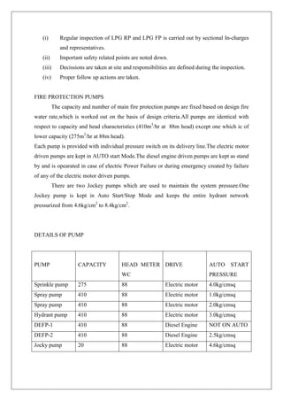
SlideShare a Scribd company logo
1 of 32
Download to read offline
A REPORT ON
INDUSTRIAL TRAINING
AT
OIL INDIA LIMITED
DULIAJAN
LPG DEPARTMENT
DECEMBER 2012
SUBMITTED BY
UPAL JYOTI BARUAH
5TH
SEMESTER,
ASSAM ENGINEERING COLLEGE,
GUWAHATI - 781013.
AKNOWLEDGMENT
We would like to offer our sincere gratitude to the respected and learned guides of Oil
India Limited, Duliajan especially Shri D. Das ,DSO(i/c) LPG, Mrs. S. Banerjee,CE(O)LPG,
Shri R.Bhagawati,SE (i) LPG, Shri M.K. Goswami, CE(E),LPG Shri P Ray Choudhury
CE(M) i/c LPG, Mrs. E.L.Wahlang Dy.Suptd. Chemist, LPG and Mrs. N.Deka E(PD) LPG
under whom we were deputed. Thanks to Shri Jharna Baruah and Shri D.K. Mahanta for
providing us the environment and other necessary facilities during our stay.
We are heartily thankful to all the managers, engineers and operators working in the
LPG department who have helped us in different ways to make our training a very productive
one.
Apart from them we are grateful to Mrs Nivedita Saikia Tamuli, T&D Officer, OIL
Duliajan and Prof. Ashok Baruah, HOD, Chemical Engineering, AEC, for their support and
encouragement.
Upal Jyoti Baruah
5th
Semester,
Department of Chemical
Engineering,
Assam Engineering College,
Guwahati.
CONTENTS
CHAPTER
NO.
TOPIC PAGE
NO
1 INTRODUCTION TO OIL 1
2 LPG RECOVERY UNIT 3
3 SAFETY SYSTEM IN RECOVERY AND FILLING PLANT 7
4 INSTRUMENTATION IN LPG 13
5 MECHANICAL MAINTENANCE OF LPG 17
6 QUALITY CONTROL LAB 21
7 ELECTRICAL MAINTENANCE 24
8 LPG FILLING 26
9 CONCLUSION 30
CHAPTER 1
AN INTRODUCTION TO OIL
The discovery of oil at Digboi, Assam marks the birth of an oil and gas company
based in Assam. The company was incorporated as a private limited company on February
18,1959 under the name “Oil India Private Limited” between the President of India, the
Burmah Oil Company Limited and Assam Oil company limited. It became a deemed public
limited company on May 4, 1961 and thus the word “private” was deleted from its name.
Presently the Oil India Limited (OIL) is an Indian public sector company under the
administrative control of the Ministry of Petroleum and Natural Gas of the Government of
India. OIL is engaged in the business of exploration, development and production of crude
oil and natural gas, transportation of crude oil and production of liquid petroleum gas. The
Company presently produces over 3.2 MMTPA (million tons per annum) of crude oil, over
5 MMSCMD of Natural Gas and over 50,000 Tones of LPG annually. Most of this emanates
from its traditionally rich oil and gas fields concentrated in the North-eastern part of India
and contribute to over 65% of total Oil & Gas produced in the region. The search for new
avenues has seen OIL spreading out its operations in onshore / offshore Orissa and Andaman,
deserts of Rajasthan, plains of Uttar Pradesh, riverbeds of Brahmaputra and offshore
Saurashtra. In Rajasthan, OIL discovered gas in 1988, heavy oil / bitumen in 1991 and started
production of gas in 1996. The company has over 100,000 square kilometres of license areas
for oil and gas exploration. It has emerged as a consistently profitable international company
with exploration blocks as far as Libya and sub-Saharan Africa.
In recent years, OIL has stepped up E & P activities significantly including Gas
monetization in the North-East India. OIL has set up the NEF (North East Frontier) project to
intensify its exploration activities in the frontier areas in North East, which are logistically
very difficult and geologically complex. Presently, seismic surveys are being carried out in
Manbhum, Pasighat and other Trust Belt areas. The Company operates a crude oil pipeline in
the North East for transportation of crude oil produced by both OIL and ONGCL in the
region to feed Numaligarh, Guwahati, Bongaigaon and Barauni refineries and a branch line to
feed Digboi refinery. OIL also sells its produced gas to different customers in Assam viz.
BVFCL, ASEB, NEEPCO, IOC (AOD), and APL and to RSEB in Rajasthan.
There are various departments in OIL and a few of them are:
Production (Oil&Gas), Civil engineering, Chemical engineering, LPG, Geological,
Electrical engineering, Instrumentation, IT, Fire and Safety, Transport, Field
communication, Field engineering, Drilling, Well logging, Geophysics, Materials, Medical,
Finance and maintenance, Training and development, Research and development
The two major products of Oil India Limited are
1.Crude Oil and Natural Gas,
2.LPG ( Liquified Petroleum Gas ) being an important value addition to the naturalgas
produced.
CHAPTER 2
LPG RECOVERY UNIT
The LPG recovery unit of OIL based at Duliajan was incorporated on 1982 and is
based on Turbo Expander Technology. The main objective of this unit is the production of
LPG from Natural Gas. The by-product of this unit is called Condensate or Heavy Gasoline.
It is certified to conform to the Quality Management System Standard: OHSAS 18001:2001,
ISO 14001:2004 and ISO 9001:2008.
LPG department of OIL has two installations, namely, (i) LPG Recovery Plant which
produces LPG and Natural Gasoline (a by-product) from natural gas and (ii) LPG Filling
Plant, which has facilities for filling of LPG cylinders as well as LPG and Natural Gasoline
road tankers. The various sections at LPG department are :(a) Recovery Plant Operation(b)
Filling Plant Operation(c) Mechanical and General Maintenance(d) Electrical(e)
Instrumentation(f) Quality control(g) Safety(h) Planning & Administration
The LPG is sold to and marketed by IOCL after being bottled or filled in tankers. The
remaining natural gas is called residue gas at 76MMSCFD which is returned back to LPG
take-off point. The residue gas is supplied to power house, domestic use, BVFCL, NTPS,
NEEPCO and AGCL.
The LPG recovery unit produces 50:50(w/w) propane-butane product and 12lb RVP
gasoline product. Gas is compressed and dehydrated and also chilled by cold liquid and cold
residue gas from top of de-butanizer. Liquid formed during condensation is then removed and
sent to de-butanizer. Remaining gas is expanded and pressure is lowered, when the gas gets
colder, more liquid condenses. Gas-liquid stream is sent to de-butanizer. The de-butanizer
overhead gas stream is brought back to warm it up. Natural gas at 80MMSCFD (design) from
LPG take-off point of production gas department is received in LPG recovery plant. The
natural gas is processed in LPG Recovery plant to produce (a) LPG (C3:C4) & (b)
Condensate. The remaining natural gas is called residue gas at 76MMSCFD which is returned
back to LPG take-off point.
OIL serves about two lakh families in the North East through supply of cooking gas,
which replaces equivalent amount of kerosene and helps environment by saving valuable
trees and providing one of the cleanest fuels.
LPG Recovery process comprises of mainly the following units:
a) Compressor.
b) Dehydrator.
c) Heat exchangers.
d) Expander.
e) De-etheriser.
f) De-butaniser.
2.1 PROCESS OF LPG PRODUCTION
Natural Gas consists of Methane, Ethane, Propane, Butane, Pentane and Hexane. The
fraction of Butane is maximum. However its fractional percentage has been decreasing.
Applying fractional distillation LPG which consists of Propane and Butane and Condensate
which consists of Pentane and Hexane can be obtained.
Natural Gas consists of Hydrocarbons along with moisture. Removal of moisture is
very important in production of LPG especially before compressors are used. These can be
moisture or any solid particle present in the gas. The liquid passes to a closed drain and the
gas is passed to a Centrifugal Compressor. The compressor is driven by a 4500 HP H.T
motor, operating on 11KV power supply. The main purpose of the scrubber is to remove
moisture and solid particles so that the power requirement is lessen. The approximate
increase in pressures in the four stages of the centrifugal compressor are as follows:
INLET: 14 Kg/cm2
STAGE 1: 18 Kg/cm2
STAGE 2: 20 Kg/cm2
STAGE 3: 28 Kg/cm2
STAGE 4: 32 Kg/cm2
When a gas is compressed its temperature is increased considerably. This gas is
divided in two paths. The flow of one is controlled and the other is open. The controlled flow
is passed through a water based heat exchanger. The opened line is passed through another
heat exchanger which is heating up deeterniser reflux. Heat of compression fed to de-
ethanizer where temperature of inlet gas is lowered from 215°F to173°F and condensation
occurs. The removal of liquids is very important in the entire process. The gas passes through
scrubber followed by another heat exchanger. The gas which now contains liquid particles
also now passes through a liquid filter which separates all liquid particles.
The liquid flows to the closed drain and the gas goes to a dehydrator. There are two
dehydrators in this plant. Each runs for 8 continuous hours. A Dehydrator consists of
molecular sieves which is of Sodium Alumina Silicate which has the capacity of absorbing
water particles from gas-water mixture. There are approximately 11,000 Kg of such material
in each dehydrator. In order to remove the absorbed water molecules the offline dehydrator a
number of processes takes place. A heat cycle occurs for 270 minutes followed by a cold
cycle which runs for about 190 minutes. This is followed by a pressurisation process in which
pressure is build up. This runs for about 15 minutes. For the next 2 minutes bed change over
takes place. Both the dehydrators are online in this period. The controlling of this process is
done using a PLC (programmed logic controller).
After dehydration, the gas particles contains dust so it has to be passed through a dust
filter. The outlet of the dust filter is divided into two lines, one contains 70% output and the
other the rest 30% both of which is passed through two heat exchanges. The condensed gas is
passed through a cold separator to separate the gas and the liquid. The liquid flows through a
heat exchanger to a deetherniser. The gas flows through an expander. The gas flows out as
residue gas and the liquid flows to the deetherniser via a heat exchanger.
The deetherniser feed is liquid from cold separator and liquid from expander. A part
of this liquid circulated within and this is called deetherniser reflux. This is heated from a part
of the gas from the centrifugal compressor. The liquid then passes to a debuteniser where
fractional distillation occurs and LPG and Condensate are obtained as product. A part of the
liquid inside the debuteniser circulates within and this is called debuteniser reflux.
2.2 FLOW DIAGRAM OF LPG PRODUCTION
Simplified flow diagram
RESIDUE GAS
LPG
CONDENSATE
INLET
GAS
COMPR.
GAS- GAS
EXCHANGER
GAS - LIQUID
EXCHANGER
TURBO-EXPANDER
EXPANDER
SEPARATOR
DE-ETHANIZERDE-BUTANIZER
BOOSTER
COMPRESSORFEED
GAS
COLD
SEPARATOR
DEHYDRATOR
CHAPTER 3
SAFETY SYSTEM IN LPG RECOVERY AND FILLING PLANT
LPG is highly inflammable substance as small leakage as 1.4% can cause 100% lower
explosive probability. So to carry out any process activity in such flammable environment,
there are areas where safety procedures must be adopted. LPG is a colorless liquid which
evaporates easily into a gas, and the leakage of even a small volume can expand into a large
hazardous zone. Since it has no smell, a little mercaptan isadded to help detect leaks.It can
burn and explode when gets mixed with air and meets a source of ignition and itcan also
cause cold burns to skin. Therefore safety is of utmost importance in LPG plant.Safety in
LPG plant.
Safety system in LPG Plants includes the following:
(1) General safety
(2) Electrical safety
(3) Work Permit System
(1) General safety
Following safety facilities are made available in LPG Recovery and Filling Plant:
 ALARM AND SHUT-DOWN SYSTEM
 ESD DEVICE
 SAFETY RELIEF VALVES
 GAS DETECTION SYSTEM
 FIRE ALARM SYSTEM, FIRE SIRENS
 FIRE PROTECTION SYSTEM
 FIRE EXTINGUISHERS
 FIRE DRILL
 REGULAR INSPECTION OF PLANT
 OTHERS
ALARM AND SHUTDOWN SYSTEM
(A) The plant control philosophy has automatic in-built safety shut-down logic to protect the
vital equipment and the Plant as a whole from any abnormal condition of operation.
Audio-visual alarm and shut-down indications are displayed in LPG Control Room. The
limits of maximum/minimum flow, pressure, temperature, level etc. of various stages of
the Plant are also continuously displayed in the computer visual display units for
monitoring the plant operation.
(B) The exact status regularly comes to computers of DCS in top control room in terms of
three different colors- (i) yellow color(for standard priority) (ii) blue color(for medium
priority) and (iii) the red color(for top priority).
(C) 24 Nos. of set points on alarm and shut-down indications related to CM 11-01 and EC 12-
01 are displayed in static screen named ALARM SHUTDOWN1, 19 nos. of set points
related to other areas are displayed in static screen named ALARM SHUTDOWN2 in
DCS.
(D)Status monitoring is done round the clock through DCS work stations. Operations of
alarm and shut-down system are tested as and when those conditions arise during day to
day plant operation and also during planned and non-planned shutdown of the plant.
(E) Testing/ Calibration is done as and when required for smooth running of the plant, also
during annual maintenance of the plant.
ESD DEVICE:
(A)It requires to press the ESD switch to stop LPG Recovery Plant in the event of any
emergency that calls for shutdown of LPG Recovery Plant.
(B) The ESD switches are provided in three different locations in the plant- (i) Top Control
Room (ii) Bottom Control Room (iii) Expander Compressor Panel.
(C) Testing is done during planned shutdown of the plant.
SAFETY RELIEF VALVES
(A)Safety Relief Valves(SRVs) are required for protection of storage tanks, pressure vessels
and piping to protect the same from overpressure.
(B) 60 nos. of SRVs are provided at storage vessels, pressure vessels and piping to protect the
same from overpressure.
(C) When the pressure of the system goes above the process set point, the SRV opens and
releases the excess pressure.
(D)SRVs are provided in the Scrubbers, Inlet Filter Separators, Dehydrators, gas flow lines,
all pressure process vessels, LPG storage vessels, LPG despatch piping etc.
(E) The discharges of the SRVs of LPG storage vessels are connected to the flare system
through a common line for safety and environmental protection.
(F) The discharges of the SRVs of LPG storage vessels are connected to the flare system
through a common venting system for safety and environmental protection.
(G)Calibration and testing is carried out once a year on scheduled date as specified by code
and test results are recorded.
GAS DETECTION SYSTEM
(A)The gas detection system consists of 28 Nos. of gas detectors which are located at the
vulnerable areas of LPG Recovery Plant and LPG Filling plant. The leakage of gas
leading to formation of explosive mixture surrounding the detectors get detected
immediately and the amount of leakage in terms of percentage of lower explosive
limit(LEL) is displayed with alarm in DCS work station of LPG control room.
(B) Testing/calibration of gas detectors is done as and when required to ensure that those are
in proper working condition. The calibration and testing of gas detectors is carried out
quarterly as per OISD guideline with proper documentation and record.
FIRE ALARM SYSTEMS, FIRE SIRENS:
(A) FIRE ALARM SYSTEM
(a) The fire alarm system consists of alarm switch glass boxes installed at 21Nos. of critical
areas in LPG Recovery and LPG Filling Plant with an audio-visual alarm panel in the
bottom control room.
(b) In case of emergency situation in any area in LPG RP and FP, it is required to break the
glass of the switch box of that area. This will give (i)an audio-visual alarm in the bottom
control room indicating the location of emergency (ii)siren in LPG Recovery and also in
LPG Filling Plantif the glass is broken in LPG Filling Plant (iii)siren in LPG Recovery
Plant if the glass is broken in LPG Recovery Plant.
(c) Testing of each point is carried out once in every month. Proper record is maintained.
(B)FIRE SIRENS
(a) Two Nos. of power operated fire sirens(ranges are 5km and 1km) are provided in LPG
RP and also in LPG FP in suitable locations to cover the whole area.
The siren having 1km range is operated in manual mode during normal fire drill, otherwise
the siren having 5km range is operated. The bigger siren is interlocked with Fire Alarm
switches for auto mode operation.
In case it is required to raise the bigger siren manually, the switch of siren on the panel of fire
sirens must be brought to manual mode and then the siren can be raised by ON/OFF switch
provided for that purpose.
(b) As per OISD guideline, Fire Siren should be as follows:
FIRE
DISASTER
ALL CLEAR
TEST
FIRE PROTECTION SYSTEM
(A) CLASSIFICATION OF PETROLEUM PRODUCTS
(1) CLASS ‘A’ Petroleum
(2) CLASS ‘B’ Petroleum below 65 degree celcius
(3) CLASS ‘C’ Petroleum below 93 degree celcius
(4) Excluded Petroleum Liquefied gases including LPG, do not fall under this
classification but form a separate category.
(B) GENERAL CONSIDERATIONS
The following fire protections are provided in LPG plant:
-Fire Water System
-Foam System
-Portable fire extinguishers
-Sand buckets
(C) BASIS OF DESIGN
The fire water system of OIL’s LPG plant is designed to meet the fire water flow
requirement for fighting two major fires simultaneously requiring largest water demand.
(D) The fire water system includes continuously pressurized over ground fire water network
of 2KM length (approximately) consisting of
(a) 3000 KLS FIRE WATER RESERVOIR WITH ADDITIONAL FACILITY OF
ANOTHER 3600 KLS FROM CENTRAL TANK FARM.
(b) FIRE PROTECTION PUMPS WITH AUTO START FACILITY
(c) HYDRANT POINTS, MONITORS, HOSES
(d) TEMPERATURE SENSING MEDIUM VELOCITY WATER SPRAY SYSTEM
THROUGH DELUGE VALVES FOR STORAGE TANKS, TANKER LOADING
AREAS, EMPTY AND FILLED CYLINDER SHEDS.
 FIRE EXTINGUISHERS
Portable Fire Extinguishers are provided at critical locations in LPG Recovery Plant and
LPG Filling Plant as follows:
(1) LPG RP: A-type -- 07 Nos
B-type – 04 Nos
C-type – 25 Nos
D-type – 25 Nos
(2) LPG FP: C-type – 31 Nos
D-type – 07 Nos
 FIRE DRILL
Fire drill is carried out forth nightly in LPG Recovery and also in LPG Filling Plant by
the plant personnel from all sections along with personnel from Fire Service Section to
test the performance of the Fire Protection System of LPG department and to take
corrective action as necessary.
 REGULAR INSPECTION OF PLANT
(i) Regular inspection of LPG RP and LPG FP is carried out by sectional In-charges
and representatives.
(ii) Important safety related points are noted down.
(iii) Decissions are taken at site and responsibilities are defined during the inspection.
(iv) Proper follow up actions are taken.
FIRE PROTECTION PUMPS
The capacity and number of main fire protection pumps are fixed based on design fire
water rate,which is worked out on the basis of design criteria.All pumps are identical with
respect to capacity and head characteristics (410m3
/hr at 88m head) except one which ic of
lower capacity (275m3
/hr at 88m head).
Each pump is provided with individual pressure switch on its delivery line.The electric motor
driven pumps are kept in AUTO start Mode.The diesel engine driven pumps are kept as stand
by and is opearated in case of electric Power Failure or during emergency created by failure
of any of the electric motor driven pumps.
There are two Jockey pumps which are used to maintain the system pressure.One
Jockey pump is kept in Auto Start/Stop Mode and keeps the entire hydrant network
pressurized from 4.6kg/cm2
to 8.4kg/cm2
.
DETAILS OF PUMP
PUMP CAPACITY HEAD METER
WC
DRIVE AUTO START
PRESSURE
Sprinkle pump 275 88 Electric motor 4.0kg/cmsq
Spray pump 410 88 Electric motor 1.0kg/cmsq
Spray pump 410 88 Electric motor 2.0kg/cmsq
Hydrant pump 410 88 Electric motor 3.0kg/cmsq
DEFP-1 410 88 Diesel Engine NOT ON AUTO
DEFP-2 410 88 Diesel Engine 2.5kg/cmsq
Jocky pump 20 88 Electric motor 4.6kg/cmsq
CHAPTER 4
INSTRUMENTATION IN LPG PLANT
4.1 WHAT IS INSTRUMENTATION?
Instrumentation is defined as the art and science of measurement and control of process
variables within a production or manufacturing area. It measures and or regulates physical
quantity or process variables such as flow, temperature, level, or pressure.
4.2 ROLE OF INSTRUMENTATION IN LPG RECOVERY UNIT
The role of instrumentation is any industry, more specifically in Oil India Ltd. can be
classified as follows:
1. Procurement.
The instrumentation department is entrusted with the following duties in the
field of process control, drilling and other related areas like laboratory, R&D
etc:
I. Selection of the process or technology.
II. Specifications of the process or technology.
III. Scrutinise of the process or technology.
2. Maintenance
In the LPG plant maintenance is given a very high priority because of safety of
the plant. A very effective maintenance is carried out through both in-house
and outsourcing. There are three types of maintenance process carries out at
LPG plant. These are:
I. Maintenance in case of break down.
II. Routine maintenance.
III. Annual maintenance.
3. Technical reports:
The instrumentation department distributes information outside OIL.
Technical presentations and reports given to OSID and other organisations are
given by this department.
The different devices used and maintained by this section are as follows:
Gas Chromatography- used for analyzing a mixture of a sample, a fully electronically
controlled device. It consists of columns and detectors situated in the oven maintained at
80’c.
Moisture Analyzer- If the temperature is less than -80’C, the moisture in the gas will become
saturated and form ice crystals which blocks the pipelines and hence has to be prevented.
This is done by placing a device at different locations for checking the amount of moisture
present and creates an electrical signals.
TCD (Thermal conductivity detector)- uses the property of thermal conductivity of gases and
converts into electrical signals unique for each and every gas imitating the same property
which are received by the calibrated and programmed computers.
Thermocouple is used for sensing temperature. Level transmitters work based on Archimedes
Principle. The different types are:
Mass flow meter- senses both gravity and volume. It carries out a lot of algorithms
considering the resonant frequency of the U wire which gives the inertia of the liquid and
temperature for gravity calculation.
Orifice flow meter- works on the Bernoulli’s principle and specifies only volume.
4.3 CONTROLLERS IN LPG RECOVERY PLANT
For instrument control, basically two control systems are available. They are as
follows
1. Distributed Control System (DCS).
2. Programmable Logic Control (PLC).
4.3.1 DISTRUBUTED CONTROL SYSTEM (DCS)
Distributed control system is a digital control system based on distributed control
philosophy. It means a control system which works on the principle of power delegation.
The control system will be at the top of the power higherchi and sub modules/nodes obtain
the power conferred by the top power higherity. To delegate power there should be some
connectivity to reach the data to all nodes. This is a network backbone associated with the
system. Basically an Ethernet dual ring network called distributed communication network
(DCN).
DCS Loops are basically of two types:
1. Sourcing type loops:-In this type of loops power flows from the DCS to field’s
equipments such as transmitters, RTDs, Thermocouples etc. Here field’s instrument acts
as load and obtain power from the loop.
2. Sinking type loops:-In this type of loops power flows to DCS to field’s equipment such
as a source and the DCS channel as load. Field instruments are externally powered.
4.3.1.1 System In Detail:
To implement a DCS, we need mainly two major components.
1. Hardware
2. Software
4.3.1.1.1 HARDWARE: They are the physically seen objects associated with the systems.
First the system has a master controller called advent controller AC460.A dual network
backbone called dual DCN is basically of Ethernet dual ring.
NODE:-Nodes are the terminals for human-machine interface (HMI).Basically these
are computer configured for the system. There are four nodes:-
1. Engineering system:- This is the control node.
2. Operation station:- This is called sub-node.
3. Information management system:- This is the node where we
generate report. Here oracle is loaded in the system.
4. AC460 itself is also a node.
I/O PANEL:-This system implements S-100 I/O or S-800 I/O system. The I/O panels
are of four types. They are-
1.Analog board:-It is basically a electronic card which provides channels
for analog I/O. This board provides 4-20 mA input and 4-20 man output.
Analog cards are of 16 channels.
2.Digital board:-It gives logical I/O for the system.
3.Thermocouple I/P board:- It channels to provide measuring
thermocouple.
4.RTD board:-It provides channels for measuring interfacing RTD. It is
high sensitive.
5. Marsheline panel:-A panel where zener barriers fuses and terminals are
installed. Here we connect the external world through cables.
6. Devices:-Such as transmitters, switches, RTD, thermo couple and other
MVI (multiple vendor interfaces) module ,for example PLC.
4.3.1.1.2 SOFTWARE: These are the programmes that cannot be seen. It includes driver
applications and other related programs written are compiled and executed in the system for
proper functioning (interfacing).
1. Data base: It is used for storing and accessing of data.
2.ADVA(adverb builder):A graphical software package which is used to
build plant object viewing through video(VDU).The plant object such as
vessels, exchanger, pipes equipments, control valves, transmitters,
compressors, expander.
3. A text package for configuring functions for defining function modules,
loops, templates. All user defined functions are inbuilt in the system in the
form FCM (function calling module), where we can invoke any function
services needed by the user.
4. A programming language to provide facility to build custom made
function. This is Taylor code language (TCL) i. e C-like language.
CHAPTER 5
MECHANICAL MAINTENANCE OF LPG RECOVERY PLANT
The responsibility of the mechanical department in the LPG Recovery Plant can be
categorised as follows:
Breakdown
Annual Maintenance
Inventory
Maintenance through contract
Building maintenance
Garden related job
The mechanical department follows a comprehensive maintenance plan which is certified to
comply with ISO 9001:2008, ISO 14001:2004 and OHAS 18001:2007. The working of the
maintenance department can be classified as follows:
Breakdown
Preventive
Predictive
Design change
Predictive is the most desired among all the classes of maintenance. Analysis of drain oil,
lube oil, vibrations, photography, sound measurement etc. is used for predicting the working of a
machine. These are done in a fixed routine for the analysis of a machine.
In LPG recovery plant, the mechanical maintenance is done in three terms. They are:-
1. Yearly
2. Fixed period (running hours for 500hrs or 1100hrs)
3. Break down.
The Mechanical Maintenance Section of the LPG department is responsible to
perform the following duties :
1) Daily plant check up to ensure smooth operation of the plant and to check lube oil level
and vibration & sound and other parameters.2) Monthly vibration measurement to ensure that
vibration levels of critical equipment are within limits and take necessary corrective
measurements.3) Periodical lube oil testing to test lube oil of three major equipment of LPG
recovery section, namely, Inlet Gas Compressor, Gear Box and Expander-Compressor.4)
Cleaning of cooling tower top chambers to ensure its proper functioning.5) Testing of SRV to
ensure its correct functioning at its Set Pressure.6) Sound level measurement to measure the
intensity of sound at specified locations and compare it with permissible limit.7)
Replacement of damaged or worn out Vee-Belt ( Endless belts used between driving pulleys
to transfer power).8) Replacement of empty Mercaptan drum of LPG storage area.9) Top up
lube oil into Expander Surge Tank to maintain a certain oil level in it.10) Air compressor lube
oil top up to maintain the required level of oil.11) Materials inspection and suitability report
for the acceptability of the materials received against direct charge Indents/purchase
orders.12) Engaging staff on overtime to complete the repairing job within the day in view of
urgent nature of work for operational as well as safety requirements. 13) Workshop job
requisition to carry out emergency repair and fabrication jobs at general workshop.14)
Breakdown maintenance of machines/ equipment.15) Preparation of tentative maintenance
schedule of air compressor.16) Ultrasonic thickness measurement to gauge metal surfaces for
the thickness.17) Handling/cleaning services and day-to-day maintenance in LPG recovery
and filling plant.18) Servicing, Inspection and Testing of LPG storage vessels.19) To replace
hot and cold insulation system of LPG recovery plant with new insulation system at a
specified time interval. 20) De-coupling of various motor devices to carry out maintenance
work on driver (motor) or driven side (pumps,compressors,fans,etc.)21) Hydro-testing of
pressure vessels and storage vessels to check the condition/health of vessel..22) Storage,
handling and disposal of lube oil and other hazardous materials.
Some common mechanical parts of the LPG recovery plant are:
5.1 Valve:
A valve is a device that regulates the flow of a fluid (gases, liquids, fluidized solids, or
slurries) by opening, closing, or partially obstructing various passageways.
5.1.1 Types of valves:
Ball valve: For on/off control without pressure drop, and ideal for quick shut-off since a 90º
turn offers complete shut-off angle, compared to multiple turns required on most manual
valves.
Butterfly valve: For flow regulation in large pipe diameters.
Choke valve: A valve that raises or lowers a solid cylinder which is placed around or inside
another cylinder which has holes or slots. Used for high pressure drops found in oil and gas
wellheads.
Check valve or non-return valve:It allows the fluid to pass in one direction only.
Gate valve: mainly for on/off control, with low pressure drop
Globe valve: It is good for regulating flow.
Needle valve: It is for accurate flow control.
5.2 Bearing:
It is used to reduce friction and for smooth running of any mechanical machines
5.2.1 Types of bearing:
1. Ball bearing
2. Roller bearing
3. Tapper bearing
4. Half type bearing /Boss type bearing
5.2.2 Structure of bearing:
The bearings are made of soft materials like carbon, copper, brass, etc.
The bearing basically consists of three parts
1. Inner
2. Racer consisting of the ball
3. Outer
5.3 Pump:
A pump is a device that moves fluids by mechanical action. Pumps can be classified into
three major groups according to the method they use to move the fluid viz. direct
lift, displacement, and gravity pumps. Pumps operate by some mechanism and
consume energy to perform mechanical work by moving the fluid. Pumps operate via many
energy sources, including manual operation, electricity, an engine of some type, or wind
power.
5.3.1 Types of Pumps
1. Centrifugal pump
2. Reciprocal pump
3. Rotary pump
4. Semi rotary pump
5.4 Compressor
A gas compressor is a mechanical device that increases the pressure of a gas by reducing
its volume. Compressors are similar to pumps both increase the pressure on a fluid and both
can transport the fluid through a pipe. As gases are compressible, the compressor also reduces
the volume of a gas. Liquids are relatively incompressible; while some can be compressed,
the main action of a pump is to pressurize and transport liquids.
5.4.1 Types of compressors:
1. Air compressor type (piston)
2. Screw type compressor (air)
CHAPTER 6
QUALITY CONTROL LABORATORY
LPG gas produced has to be maintained at a constant vapour pressure so that it can be
stored in cylinder or tanker. This has been standardized by the Bureau of Indian Standards
through IS 4576:1999.The vapour pressure of the commercial butane-propane mixture (50%
propane-50%butane) has been recommended at 16.87 kgf/cm², maximum at 65ºC. In OIL,
Duliajan it is maintained at 830-930KPa(upper limit) and 200KPa(lower limit),maximum at
40ºC.Also the composition, density has to be maintained at a standard value.
6.1 Tests for Quality Control:
6.1.1 Vapour Pressure:
Measurement of vapour pressure is done with the help of pressure gauge. Firstly the
whole apparatus is filled with liquid LPG. Then valve is slowly open to let the vapour escape
into air, so that only liquid LPG is maintained in the apparatus. Temperature at 40ºC is
maintained by the temperature bath, where the apparatus is dipped into. It is checked by
means of a temperature gauge. The lower apparatus is then removed, which is 20% cc of the
upper apparatus. This allows sufficient volume to the upper apparatus.
6.1.2 Doctor’s Test:
This method is intended primarily for the detection of marcaptan in motor fuel and similar
petroleum products. It is in-applicable in the presence of more than slide trace of peroxides.
In this method the sample is shaken with Sodium Plum bite solution small quantity of
powdered sulpher added and the mixture is shaken again. The presence of marcaptan of
hydrogen sulphide or both is indicated by de-colorization of the sulphar floating at the oil-
water interface or by de-colorization of either of the phase.
Marcaptans may have adverse effects on certain fuel systems.Illastomers may be
corrosive towards fuel system metals and produce an offensive odour the doctor test provides
a quick simple method of detecting the presence of marcaptans,hydrogen sulphide,elemental
sulphar and trace level of peroxides. A graduated cylinder of 50ml capacity with a ground
glass stopper is used as an apparatus for doctor’s test. The complete solution for doctor’s test
is a mixture of sodium plum bite solution(doctor’s reagent),8ml iso-octane,a pinch of sulphur
powder.
6.1.3 Density measurement:
For this, a chamber of fibre glass with steel cage is used. It contains a Hydro-meter(for
measuring specific gravity and density) and a thermometer(for measuring temperature).LPG
vapour is poured into it, which then condenses to liquid at low pressure(atmospheric
pressure).Therefore we get the specific gravity(or density) at a certain temperature.
6.1.4 Weathering Test:
A centrifugal test tube (100 ml) is used.LPG vapour is poured into it, which then
condenses to liquid at low pressure(atmospheric pressure).The temperature is noted with the
help of a temperature gauge. Temperature at 95% evaporation(ie at 5 ml of the liquid),should
not be more than 2ºC.If it is more than 2ºC,it will mean that the LPG contains heavier
particles(hydrogen sulphide,water).
6.1.5 Gas Chromatography
Gas chromatography (GC), is a common type of chromatography used in analytical
chemistry for separating and analysing compounds that can be
vaporized without decomposition. In simple words, gas chromatography is used for the
analysis of different components and its quantity. There are two phases in a Gas
chromatograph, a stationary phase and a mobile phase. The stationary phase is a 1m to 20m
tube of Stainless Steel inside which a stationary bed of Aluminium Oxide or Alumina is
placed at isothermal condition at 80O
C. The mobile phase is H2 which is flows at 30cc/sec.
The gas is mixed with the mobile phase and flows through the stationary bed. Depending on
some physical properties like size of the molecule, affinity towards the bed, polarity etc the
molecules of different components take different and a unique time, called Retention time, to
pass through the bed. At the end of the bed there is a Thermal Conductivity Detector (TDC)
which has 4 filaments, 2 called reference filament and 2 others called measuring gas filament.
These filaments are very precisely calibrated. From the TDC the amount of a component can
be measured. Thus, from the retention time and the TDC the different components and its
quantity can be measured.
Apart from this unit there is a GC sample panel. This panel is used to collect the
samples, regulate it and access the multiple samples and convert it into one.
The GC instrument used in the Quality Control Lab of LPG Recovery Unit has 4
columns for more accuracy in measurement. The GC requires a few gases for analysis. These
are as follows:
Helium: Helium is used for as the carrier gas.
Hydrogen: It is used for combustion of the gas to be tested.
Nitrogen: Nitrogen is used for the operation of valves.
Air: Air is also used for the combustion of gases with higher molecular
weight.
The gases are present at a constant pressure of 4 Bar. Helium is purchased in cylinders while
the rest gases are produced by a generator. The gases are dried using Silica Gel and molecular
sieves.
CHAPTER 7
ELECTRICAL MAINTENANCE
The power house of OIL generates 14.45 MW with the help of two gas turbines which
are alternatively at running and standby modes. The power house supplies 11KV to the
substation in the LPG plant through two underground cables. This incoming power is sent
into the feeder from two different power houses. These two sections are connected by a bus
coupler which is used only when the maintenance job needs to be done. From one the 11KV
is supplied to the spare feeder, 4500HP motor starter panel and to a transformer of 1000KVA
capacity which steps 11000V down to 415V. There are 8 vacuum circuit breakers. It is
monitored by protective relays such as VCB, ACB, SF6 of the circuits. UPS system gives an
uninterrupted power supply normally of AC current with a battery backup of 120KVA
capacity. There are 2 types of UPS in which input is 415V but outputs are 415V and 110V. A
battery converts a voltage input of AC to DC. A 110V Ni-Cd battery set is used. Another
auto-transformer other than the two in the feeder circuits produce 450V line. It is a part of
motor starter panel. During starting of motor the load might reach seven times its full load
and then drop back which cannot be allowed. To reduce this we use this auto-transformer
starter for 20 seconds and then give back to the normal system. Motor control centre (MCC)
is provided by the 415V bus. Tripping is a condition when difference between the incoming
and outgoing currents of the isolator is more than a given value and the on-off switch of the
isolator turns off automatically.
7.1 Autotransformer
Autotransformer is used for applying reduced voltage to stator during starting. Thereby the
starting current is reduced. The auto-transformer is provided with change-over switch. As the
motor comes to full speed, the change-over switch is thrown over to run position.
7.2 Circuit breaker
Circuit Breaker is an automatic device capable of making and breaking an electric circuit
under normal and abnormal conditions such as short circuits. The part of the circuit breakers
connected in one phase is called the pole. A circuit-breaker suitable for three phase system is
called a triple pole circuit breaker. Each pole of the circuit breaker comprises one or more
interrupts or arc-extinguishing chambers. The interrupters are mounted on support insulators.
The interrupter encloses a pair of fixed and moving contact. The moving contacts can be
drawn apart by means of the operating links or the operating medium. The operating
mechanism of the circuit-breaker gives the necessary energy for opening and closing of
contacts of the circuit-breakers. The arc produced by the separation of current carrying
contacts is interrupted by a suitable medium and by adopting suitable techniques for
extinction. Circuit Breaker is used for opening and closing circuits for normal switching
operations. During short circuits or abnormal conditions, relay operates and gives opening
command to circuit-breaker and circuit is opened automatically.
7.2.1 Types of Circuit Breaker in LPG plant
Air Circuit Breaker (ACB): It utilizes air at atmospheric pressure for arc-extinction.
Vacuum Circuit Breaker (VCB): The fixed and moving contacts are housed inside a
permanently sealed vacuum interrupter. The arc is quenched as the contacts are
separated in high vacuum.
ELECTRICAL LINE DIAGRAM
CHAPTER 8
LPG FILLING PLANT
Tasks carried out at LPG Filling Plant are :
 LPG cylinder filling and dispatch
 LPG tanker filling and dispatch
 Condensate tanker filling and dispatch
 Regular safety check
 Routine maintenance of the installation
Oil India limited introduces a fully automatic bottling system in the LPG filling plant
which is based on different types of photo-electric sensors, Crisplant universal controller
(CUC)and HMI(human-machine interface).The whole filling unit consists a filling machine
called Carousel filling machine. Chain conveyor with 5 gear boxes operated by 5 motors. The
Carousel machine itself uses a motor of power 1.3 KW.The process works in three stages-
weighing unit, filling unit and checking unit.
The weighing unit consists of following components. They are-
 HMI panel with support
 Pusher
 Check scale
The standard weighing range is from 2 to 120 kg in graduating of 100gm.
The photocells or photo-electric sensors used in the system are named as B01 , B02……B24
and C01,C02…etc.
CAROUSEL MACHINE
 The carousel machine consists of a carousel frame with 24 filling machines ; running
wheels and running rail, central column for gas and air and driving unit.
 The carousel frame is a circular aluminium alloy construction and the whole
construction is supported by aluminium alloy wheels with ball bearings.
 The aluminium alloy wheels run on a rail fastened to the floor.
 Normally gas is led through the bottom and air through the top of the central column.
 The main LPG conveyor track to carousel is also connected with carousel return line
(37.5 mm) along with release valve and safety valve.
A 12 mm line is also connected with the carousel return line for filling LPG in the under
filled cylinders
Operation:
The LPG is pumped to LPG Filling Plant from LPG storage vessels at LPG Recovery
Plant. The incoming LPG pressure in the pipeline is about 14kg/cm2. The cylinder consists of a
head ring, 3 fins, valve, high pressure seamed cylinder and a foot ring. The inside of the valve is
installed with an O-ring and a valve pin. The valve needs to be checked for any leak possible.
The bottling capacity of the plant is about 6000-7000 cylinders per day. The empty cylinders are
first marked by tare weight marking and their marked weights are stored by a HMI device called
pre-check scale. The marked cylinders go to Carousel machine by chain conveyor. In Carousel
machine the empty cylinders are first sensed by photo-electric sensors. In each filling gun two
sensors are linked which are placed at the top and at the bottom side of the cylinder. The bottom
side sensor is called wheel arm sensor. The bottom photo-cell senses the position of the cylinder
on the machine. The top photocell senses the cylinder and gives instruction to the gun. Then the
respective gun shoots the respective cylinder. The cylinder moves in a revolution for a minute.
The gun fills the empty cylinder within one minute. The LPG filled in the cylinder should be of
weight 14.2 kg. If the gun is unable to fill the cylinder within one minute for delay error, the
cylinder will again revolve for one minute. In the outlet of the machine has a puller with sensor
which allows only those cylinders filled up to the standard weight to go out of the machine,
otherwise it will return back the cylinder to the machine again. The cylinders are introduced
through a check scale, which checks the over weighted cylinders and bypass them to another
section called correction unit by pusher with photo-electric sensor. The over weighted cylinders
are manipulated up to the stander by manual filling. This over weighted range is considered as
+200gm.Now the corrected cylinders are lined up with the other cylinders. Now the cylinders are
fed to Gas detector and O’ring detector unit to check the leakages and damages. In this unit the
damaged cylinders are rejected.The tested cylinders are then fed to counting unit to count by a
sensor and stored. In hot air sealing unit the cylinders are sealed and fed to transportation section.
CONCLUSION
The vocational training at the LPG Recovery Plant at OIL, Duliajan exposed us to the
practical environment of engineering. We came to know about the practical problems faced in
an industry. The measures of safety in an industry are as important as production. We also
came to know that the smooth functioning of an industry depends to a large extent on the
mutual co-operation among its different wings. Apart from that we enjoyed interacting with
the employees and came to know about their experience in working at OIL.

More Related Content

What's hot

project on enhancement of LPG recovery, GAIL
project on enhancement of LPG recovery, GAILproject on enhancement of LPG recovery, GAIL
project on enhancement of LPG recovery, GAILKumar Sanu Mahato
 
Iocl training report
Iocl training reportIocl training report
Iocl training reportAmitgomey
 
Report on industrial training at indian oil corporation ltd,barauni refinery
Report on industrial training at indian oil corporation ltd,barauni refineryReport on industrial training at indian oil corporation ltd,barauni refinery
Report on industrial training at indian oil corporation ltd,barauni refineryMukul Kumar
 
Indian Oil: Vocational Training Report 2013
Indian Oil: Vocational Training Report 2013Indian Oil: Vocational Training Report 2013
Indian Oil: Vocational Training Report 2013Pawan Kumar
 
summer training report of Iocl,haldia
summer training report of Iocl,haldiasummer training report of Iocl,haldia
summer training report of Iocl,haldiasumanscience
 
Iocl industrial training_chemical_engineering_report
Iocl industrial training_chemical_engineering_reportIocl industrial training_chemical_engineering_report
Iocl industrial training_chemical_engineering_reportAfzal Reza
 
Oil and Natural Gas Corporation of India, summer traning report
Oil and Natural Gas Corporation of India, summer traning reportOil and Natural Gas Corporation of India, summer traning report
Oil and Natural Gas Corporation of India, summer traning reportNishant Nirala
 
Project Report in GAIL(India) Limited_Prakash
Project Report in GAIL(India) Limited_PrakashProject Report in GAIL(India) Limited_Prakash
Project Report in GAIL(India) Limited_PrakashPrakash Chand Baliwal
 
Summer Training Report at IOCL (chemical engineering)
Summer Training Report at IOCL (chemical engineering)Summer Training Report at IOCL (chemical engineering)
Summer Training Report at IOCL (chemical engineering)Gaurav Singh
 
Ongc drilling services introduction
Ongc drilling services introductionOngc drilling services introduction
Ongc drilling services introductionDeepak Chandak
 
Summer Training Report On Indian Oil Corporation Ltd.
Summer Training Report On Indian Oil Corporation Ltd.Summer Training Report On Indian Oil Corporation Ltd.
Summer Training Report On Indian Oil Corporation Ltd.Nitin Kumar Verma
 

What's hot (20)

Ongc report
Ongc reportOngc report
Ongc report
 
Natural Gas in India
Natural Gas in IndiaNatural Gas in India
Natural Gas in India
 
project on enhancement of LPG recovery, GAIL
project on enhancement of LPG recovery, GAILproject on enhancement of LPG recovery, GAIL
project on enhancement of LPG recovery, GAIL
 
Flowsheet ONGC
Flowsheet ONGCFlowsheet ONGC
Flowsheet ONGC
 
Ongc report
Ongc reportOngc report
Ongc report
 
Iocl training report
Iocl training reportIocl training report
Iocl training report
 
Report on industrial training at indian oil corporation ltd,barauni refinery
Report on industrial training at indian oil corporation ltd,barauni refineryReport on industrial training at indian oil corporation ltd,barauni refinery
Report on industrial training at indian oil corporation ltd,barauni refinery
 
IOCL Training Report
IOCL Training ReportIOCL Training Report
IOCL Training Report
 
Indian Oil: Vocational Training Report 2013
Indian Oil: Vocational Training Report 2013Indian Oil: Vocational Training Report 2013
Indian Oil: Vocational Training Report 2013
 
summer training report of Iocl,haldia
summer training report of Iocl,haldiasummer training report of Iocl,haldia
summer training report of Iocl,haldia
 
Iocl industrial training_chemical_engineering_report
Iocl industrial training_chemical_engineering_reportIocl industrial training_chemical_engineering_report
Iocl industrial training_chemical_engineering_report
 
ONGC Summer Training Report
ONGC Summer Training ReportONGC Summer Training Report
ONGC Summer Training Report
 
Oil and Natural Gas Corporation of India, summer traning report
Oil and Natural Gas Corporation of India, summer traning reportOil and Natural Gas Corporation of India, summer traning report
Oil and Natural Gas Corporation of India, summer traning report
 
Project Report in GAIL(India) Limited_Prakash
Project Report in GAIL(India) Limited_PrakashProject Report in GAIL(India) Limited_Prakash
Project Report in GAIL(India) Limited_Prakash
 
Indian oil industry
Indian oil industryIndian oil industry
Indian oil industry
 
Summer Training Report at IOCL (chemical engineering)
Summer Training Report at IOCL (chemical engineering)Summer Training Report at IOCL (chemical engineering)
Summer Training Report at IOCL (chemical engineering)
 
Ongc drilling services introduction
Ongc drilling services introductionOngc drilling services introduction
Ongc drilling services introduction
 
Lecture 9 natural gas processes
Lecture 9 natural gas processesLecture 9 natural gas processes
Lecture 9 natural gas processes
 
LNG
LNGLNG
LNG
 
Summer Training Report On Indian Oil Corporation Ltd.
Summer Training Report On Indian Oil Corporation Ltd.Summer Training Report On Indian Oil Corporation Ltd.
Summer Training Report On Indian Oil Corporation Ltd.
 

Similar to Training report Oil India Limited LPG, Duliajan by upal jb

PROJECT REPORT ON VARIOUS MECHANICAL UNITS INVOLVED IN THE BOTTLING OF LPG CY...
PROJECT REPORT ON VARIOUS MECHANICAL UNITS INVOLVED IN THE BOTTLING OF LPG CY...PROJECT REPORT ON VARIOUS MECHANICAL UNITS INVOLVED IN THE BOTTLING OF LPG CY...
PROJECT REPORT ON VARIOUS MECHANICAL UNITS INVOLVED IN THE BOTTLING OF LPG CY...Mohit Dhull
 
WORD FORMAT PROJECT REPORT ON VARIOUS MECHANICAL UNITS INVOLVED IN THE BOTTLI...
WORD FORMAT PROJECT REPORT ON VARIOUS MECHANICAL UNITS INVOLVED IN THE BOTTLI...WORD FORMAT PROJECT REPORT ON VARIOUS MECHANICAL UNITS INVOLVED IN THE BOTTLI...
WORD FORMAT PROJECT REPORT ON VARIOUS MECHANICAL UNITS INVOLVED IN THE BOTTLI...Mohit Dhull
 
Hiren ongc report
Hiren ongc reportHiren ongc report
Hiren ongc reportHiren Patel
 
ONGC HAZIRA PROJECT REPORT
ONGC HAZIRA PROJECT REPORTONGC HAZIRA PROJECT REPORT
ONGC HAZIRA PROJECT REPORTNikhil Chavda
 
Amit Nitharwal report (2)
Amit Nitharwal report (2)Amit Nitharwal report (2)
Amit Nitharwal report (2)Amit Nitharwal
 
Industrial Training report at ONGC
Industrial Training report at ONGCIndustrial Training report at ONGC
Industrial Training report at ONGCShouvik Ash
 
Sylhet field work 2019
Sylhet field work 2019Sylhet field work 2019
Sylhet field work 2019Srimontorumpa
 
Report on NG Processing Plant
Report on NG Processing PlantReport on NG Processing Plant
Report on NG Processing PlantIftekhar Hussain
 
Final internship refinery Presentation (1).pptx
Final internship refinery Presentation (1).pptxFinal internship refinery Presentation (1).pptx
Final internship refinery Presentation (1).pptxAdisanu
 
Refining Process
Refining ProcessRefining Process
Refining ProcessMubarik Rao
 
INDIAN OIL CORPORATION LIMITED
INDIAN OIL CORPORATION LIMITEDINDIAN OIL CORPORATION LIMITED
INDIAN OIL CORPORATION LIMITEDRahul Kumar Mahto
 
final internship report
final internship reportfinal internship report
final internship reportUmesh kumar
 
ROLE OF C & I IN FERTILIZER PRODUCTION PLANT
ROLE OF C & I IN FERTILIZER PRODUCTION PLANTROLE OF C & I IN FERTILIZER PRODUCTION PLANT
ROLE OF C & I IN FERTILIZER PRODUCTION PLANTGaurav Rai
 
Pakistan Oilfields Limted (POL) Internship Report
Pakistan Oilfields Limted (POL) Internship ReportPakistan Oilfields Limted (POL) Internship Report
Pakistan Oilfields Limted (POL) Internship ReportMuneeb Ur Rahman
 
internship report by usama
internship report by usamainternship report by usama
internship report by usamamuhammad usama
 
ONGC_ internship _ report please don't edit directly make a copy of this file...
ONGC_ internship _ report please don't edit directly make a copy of this file...ONGC_ internship _ report please don't edit directly make a copy of this file...
ONGC_ internship _ report please don't edit directly make a copy of this file...SURENDRASINGH87542
 

Similar to Training report Oil India Limited LPG, Duliajan by upal jb (20)

PROJECT REPORT ON VARIOUS MECHANICAL UNITS INVOLVED IN THE BOTTLING OF LPG CY...
PROJECT REPORT ON VARIOUS MECHANICAL UNITS INVOLVED IN THE BOTTLING OF LPG CY...PROJECT REPORT ON VARIOUS MECHANICAL UNITS INVOLVED IN THE BOTTLING OF LPG CY...
PROJECT REPORT ON VARIOUS MECHANICAL UNITS INVOLVED IN THE BOTTLING OF LPG CY...
 
WORD FORMAT PROJECT REPORT ON VARIOUS MECHANICAL UNITS INVOLVED IN THE BOTTLI...
WORD FORMAT PROJECT REPORT ON VARIOUS MECHANICAL UNITS INVOLVED IN THE BOTTLI...WORD FORMAT PROJECT REPORT ON VARIOUS MECHANICAL UNITS INVOLVED IN THE BOTTLI...
WORD FORMAT PROJECT REPORT ON VARIOUS MECHANICAL UNITS INVOLVED IN THE BOTTLI...
 
Hiren ongc report
Hiren ongc reportHiren ongc report
Hiren ongc report
 
ONGC HAZIRA PROJECT REPORT
ONGC HAZIRA PROJECT REPORTONGC HAZIRA PROJECT REPORT
ONGC HAZIRA PROJECT REPORT
 
Amit Nitharwal report (2)
Amit Nitharwal report (2)Amit Nitharwal report (2)
Amit Nitharwal report (2)
 
Industrial Training report at ONGC
Industrial Training report at ONGCIndustrial Training report at ONGC
Industrial Training report at ONGC
 
DIGBOI Rajan
DIGBOI RajanDIGBOI Rajan
DIGBOI Rajan
 
Sylhet field work 2019
Sylhet field work 2019Sylhet field work 2019
Sylhet field work 2019
 
Report on NG Processing Plant
Report on NG Processing PlantReport on NG Processing Plant
Report on NG Processing Plant
 
Final internship refinery Presentation (1).pptx
Final internship refinery Presentation (1).pptxFinal internship refinery Presentation (1).pptx
Final internship refinery Presentation (1).pptx
 
Refining Process
Refining ProcessRefining Process
Refining Process
 
INDIAN OIL CORPORATION LIMITED
INDIAN OIL CORPORATION LIMITEDINDIAN OIL CORPORATION LIMITED
INDIAN OIL CORPORATION LIMITED
 
final internship report
final internship reportfinal internship report
final internship report
 
ROLE OF C & I IN FERTILIZER PRODUCTION PLANT
ROLE OF C & I IN FERTILIZER PRODUCTION PLANTROLE OF C & I IN FERTILIZER PRODUCTION PLANT
ROLE OF C & I IN FERTILIZER PRODUCTION PLANT
 
Ghulam Farid cv
Ghulam Farid cvGhulam Farid cv
Ghulam Farid cv
 
123
123123
123
 
D05711618
D05711618D05711618
D05711618
 
Pakistan Oilfields Limted (POL) Internship Report
Pakistan Oilfields Limted (POL) Internship ReportPakistan Oilfields Limted (POL) Internship Report
Pakistan Oilfields Limted (POL) Internship Report
 
internship report by usama
internship report by usamainternship report by usama
internship report by usama
 
ONGC_ internship _ report please don't edit directly make a copy of this file...
ONGC_ internship _ report please don't edit directly make a copy of this file...ONGC_ internship _ report please don't edit directly make a copy of this file...
ONGC_ internship _ report please don't edit directly make a copy of this file...
 

Recently uploaded

SOCIAL AND HISTORICAL CONTEXT - LFTVD.pptx
SOCIAL AND HISTORICAL CONTEXT - LFTVD.pptxSOCIAL AND HISTORICAL CONTEXT - LFTVD.pptx
SOCIAL AND HISTORICAL CONTEXT - LFTVD.pptxiammrhaywood
 
URLs and Routing in the Odoo 17 Website App
URLs and Routing in the Odoo 17 Website AppURLs and Routing in the Odoo 17 Website App
URLs and Routing in the Odoo 17 Website AppCeline George
 
Hybridoma Technology ( Production , Purification , and Application )
Hybridoma Technology  ( Production , Purification , and Application  ) Hybridoma Technology  ( Production , Purification , and Application  )
Hybridoma Technology ( Production , Purification , and Application ) Sakshi Ghasle
 
Separation of Lanthanides/ Lanthanides and Actinides
Separation of Lanthanides/ Lanthanides and ActinidesSeparation of Lanthanides/ Lanthanides and Actinides
Separation of Lanthanides/ Lanthanides and ActinidesFatimaKhan178732
 
Accessible design: Minimum effort, maximum impact
Accessible design: Minimum effort, maximum impactAccessible design: Minimum effort, maximum impact
Accessible design: Minimum effort, maximum impactdawncurless
 
Alper Gobel In Media Res Media Component
Alper Gobel In Media Res Media ComponentAlper Gobel In Media Res Media Component
Alper Gobel In Media Res Media ComponentInMediaRes1
 
Arihant handbook biology for class 11 .pdf
Arihant handbook biology for class 11 .pdfArihant handbook biology for class 11 .pdf
Arihant handbook biology for class 11 .pdfchloefrazer622
 
18-04-UA_REPORT_MEDIALITERAСY_INDEX-DM_23-1-final-eng.pdf
18-04-UA_REPORT_MEDIALITERAСY_INDEX-DM_23-1-final-eng.pdf18-04-UA_REPORT_MEDIALITERAСY_INDEX-DM_23-1-final-eng.pdf
18-04-UA_REPORT_MEDIALITERAСY_INDEX-DM_23-1-final-eng.pdfssuser54595a
 
APM Welcome, APM North West Network Conference, Synergies Across Sectors
APM Welcome, APM North West Network Conference, Synergies Across SectorsAPM Welcome, APM North West Network Conference, Synergies Across Sectors
APM Welcome, APM North West Network Conference, Synergies Across SectorsAssociation for Project Management
 
Concept of Vouching. B.Com(Hons) /B.Compdf
Concept of Vouching. B.Com(Hons) /B.CompdfConcept of Vouching. B.Com(Hons) /B.Compdf
Concept of Vouching. B.Com(Hons) /B.CompdfUmakantAnnand
 
mini mental status format.docx
mini    mental       status     format.docxmini    mental       status     format.docx
mini mental status format.docxPoojaSen20
 
Introduction to AI in Higher Education_draft.pptx
Introduction to AI in Higher Education_draft.pptxIntroduction to AI in Higher Education_draft.pptx
Introduction to AI in Higher Education_draft.pptxpboyjonauth
 
Call Girls in Dwarka Mor Delhi Contact Us 9654467111
Call Girls in Dwarka Mor Delhi Contact Us 9654467111Call Girls in Dwarka Mor Delhi Contact Us 9654467111
Call Girls in Dwarka Mor Delhi Contact Us 9654467111Sapana Sha
 
Science 7 - LAND and SEA BREEZE and its Characteristics
Science 7 - LAND and SEA BREEZE and its CharacteristicsScience 7 - LAND and SEA BREEZE and its Characteristics
Science 7 - LAND and SEA BREEZE and its CharacteristicsKarinaGenton
 
Introduction to ArtificiaI Intelligence in Higher Education
Introduction to ArtificiaI Intelligence in Higher EducationIntroduction to ArtificiaI Intelligence in Higher Education
Introduction to ArtificiaI Intelligence in Higher Educationpboyjonauth
 
Contemporary philippine arts from the regions_PPT_Module_12 [Autosaved] (1).pptx
Contemporary philippine arts from the regions_PPT_Module_12 [Autosaved] (1).pptxContemporary philippine arts from the regions_PPT_Module_12 [Autosaved] (1).pptx
Contemporary philippine arts from the regions_PPT_Module_12 [Autosaved] (1).pptxRoyAbrique
 
Software Engineering Methodologies (overview)
Software Engineering Methodologies (overview)Software Engineering Methodologies (overview)
Software Engineering Methodologies (overview)eniolaolutunde
 
MENTAL STATUS EXAMINATION format.docx
MENTAL     STATUS EXAMINATION format.docxMENTAL     STATUS EXAMINATION format.docx
MENTAL STATUS EXAMINATION format.docxPoojaSen20
 
CARE OF CHILD IN INCUBATOR..........pptx
CARE OF CHILD IN INCUBATOR..........pptxCARE OF CHILD IN INCUBATOR..........pptx
CARE OF CHILD IN INCUBATOR..........pptxGaneshChakor2
 
microwave assisted reaction. General introduction
microwave assisted reaction. General introductionmicrowave assisted reaction. General introduction
microwave assisted reaction. General introductionMaksud Ahmed
 

Recently uploaded (20)

SOCIAL AND HISTORICAL CONTEXT - LFTVD.pptx
SOCIAL AND HISTORICAL CONTEXT - LFTVD.pptxSOCIAL AND HISTORICAL CONTEXT - LFTVD.pptx
SOCIAL AND HISTORICAL CONTEXT - LFTVD.pptx
 
URLs and Routing in the Odoo 17 Website App
URLs and Routing in the Odoo 17 Website AppURLs and Routing in the Odoo 17 Website App
URLs and Routing in the Odoo 17 Website App
 
Hybridoma Technology ( Production , Purification , and Application )
Hybridoma Technology  ( Production , Purification , and Application  ) Hybridoma Technology  ( Production , Purification , and Application  )
Hybridoma Technology ( Production , Purification , and Application )
 
Separation of Lanthanides/ Lanthanides and Actinides
Separation of Lanthanides/ Lanthanides and ActinidesSeparation of Lanthanides/ Lanthanides and Actinides
Separation of Lanthanides/ Lanthanides and Actinides
 
Accessible design: Minimum effort, maximum impact
Accessible design: Minimum effort, maximum impactAccessible design: Minimum effort, maximum impact
Accessible design: Minimum effort, maximum impact
 
Alper Gobel In Media Res Media Component
Alper Gobel In Media Res Media ComponentAlper Gobel In Media Res Media Component
Alper Gobel In Media Res Media Component
 
Arihant handbook biology for class 11 .pdf
Arihant handbook biology for class 11 .pdfArihant handbook biology for class 11 .pdf
Arihant handbook biology for class 11 .pdf
 
18-04-UA_REPORT_MEDIALITERAСY_INDEX-DM_23-1-final-eng.pdf
18-04-UA_REPORT_MEDIALITERAСY_INDEX-DM_23-1-final-eng.pdf18-04-UA_REPORT_MEDIALITERAСY_INDEX-DM_23-1-final-eng.pdf
18-04-UA_REPORT_MEDIALITERAСY_INDEX-DM_23-1-final-eng.pdf
 
APM Welcome, APM North West Network Conference, Synergies Across Sectors
APM Welcome, APM North West Network Conference, Synergies Across SectorsAPM Welcome, APM North West Network Conference, Synergies Across Sectors
APM Welcome, APM North West Network Conference, Synergies Across Sectors
 
Concept of Vouching. B.Com(Hons) /B.Compdf
Concept of Vouching. B.Com(Hons) /B.CompdfConcept of Vouching. B.Com(Hons) /B.Compdf
Concept of Vouching. B.Com(Hons) /B.Compdf
 
mini mental status format.docx
mini    mental       status     format.docxmini    mental       status     format.docx
mini mental status format.docx
 
Introduction to AI in Higher Education_draft.pptx
Introduction to AI in Higher Education_draft.pptxIntroduction to AI in Higher Education_draft.pptx
Introduction to AI in Higher Education_draft.pptx
 
Call Girls in Dwarka Mor Delhi Contact Us 9654467111
Call Girls in Dwarka Mor Delhi Contact Us 9654467111Call Girls in Dwarka Mor Delhi Contact Us 9654467111
Call Girls in Dwarka Mor Delhi Contact Us 9654467111
 
Science 7 - LAND and SEA BREEZE and its Characteristics
Science 7 - LAND and SEA BREEZE and its CharacteristicsScience 7 - LAND and SEA BREEZE and its Characteristics
Science 7 - LAND and SEA BREEZE and its Characteristics
 
Introduction to ArtificiaI Intelligence in Higher Education
Introduction to ArtificiaI Intelligence in Higher EducationIntroduction to ArtificiaI Intelligence in Higher Education
Introduction to ArtificiaI Intelligence in Higher Education
 
Contemporary philippine arts from the regions_PPT_Module_12 [Autosaved] (1).pptx
Contemporary philippine arts from the regions_PPT_Module_12 [Autosaved] (1).pptxContemporary philippine arts from the regions_PPT_Module_12 [Autosaved] (1).pptx
Contemporary philippine arts from the regions_PPT_Module_12 [Autosaved] (1).pptx
 
Software Engineering Methodologies (overview)
Software Engineering Methodologies (overview)Software Engineering Methodologies (overview)
Software Engineering Methodologies (overview)
 
MENTAL STATUS EXAMINATION format.docx
MENTAL     STATUS EXAMINATION format.docxMENTAL     STATUS EXAMINATION format.docx
MENTAL STATUS EXAMINATION format.docx
 
CARE OF CHILD IN INCUBATOR..........pptx
CARE OF CHILD IN INCUBATOR..........pptxCARE OF CHILD IN INCUBATOR..........pptx
CARE OF CHILD IN INCUBATOR..........pptx
 
microwave assisted reaction. General introduction
microwave assisted reaction. General introductionmicrowave assisted reaction. General introduction
microwave assisted reaction. General introduction
 

Training report Oil India Limited LPG, Duliajan by upal jb

  • 1. A REPORT ON INDUSTRIAL TRAINING AT OIL INDIA LIMITED DULIAJAN LPG DEPARTMENT DECEMBER 2012 SUBMITTED BY UPAL JYOTI BARUAH 5TH SEMESTER, ASSAM ENGINEERING COLLEGE, GUWAHATI - 781013.
  • 2. AKNOWLEDGMENT We would like to offer our sincere gratitude to the respected and learned guides of Oil India Limited, Duliajan especially Shri D. Das ,DSO(i/c) LPG, Mrs. S. Banerjee,CE(O)LPG, Shri R.Bhagawati,SE (i) LPG, Shri M.K. Goswami, CE(E),LPG Shri P Ray Choudhury CE(M) i/c LPG, Mrs. E.L.Wahlang Dy.Suptd. Chemist, LPG and Mrs. N.Deka E(PD) LPG under whom we were deputed. Thanks to Shri Jharna Baruah and Shri D.K. Mahanta for providing us the environment and other necessary facilities during our stay. We are heartily thankful to all the managers, engineers and operators working in the LPG department who have helped us in different ways to make our training a very productive one. Apart from them we are grateful to Mrs Nivedita Saikia Tamuli, T&D Officer, OIL Duliajan and Prof. Ashok Baruah, HOD, Chemical Engineering, AEC, for their support and encouragement. Upal Jyoti Baruah 5th Semester, Department of Chemical Engineering, Assam Engineering College, Guwahati.
  • 3. CONTENTS CHAPTER NO. TOPIC PAGE NO 1 INTRODUCTION TO OIL 1 2 LPG RECOVERY UNIT 3 3 SAFETY SYSTEM IN RECOVERY AND FILLING PLANT 7 4 INSTRUMENTATION IN LPG 13 5 MECHANICAL MAINTENANCE OF LPG 17 6 QUALITY CONTROL LAB 21 7 ELECTRICAL MAINTENANCE 24 8 LPG FILLING 26 9 CONCLUSION 30
  • 4. CHAPTER 1 AN INTRODUCTION TO OIL The discovery of oil at Digboi, Assam marks the birth of an oil and gas company based in Assam. The company was incorporated as a private limited company on February 18,1959 under the name “Oil India Private Limited” between the President of India, the Burmah Oil Company Limited and Assam Oil company limited. It became a deemed public limited company on May 4, 1961 and thus the word “private” was deleted from its name. Presently the Oil India Limited (OIL) is an Indian public sector company under the administrative control of the Ministry of Petroleum and Natural Gas of the Government of India. OIL is engaged in the business of exploration, development and production of crude oil and natural gas, transportation of crude oil and production of liquid petroleum gas. The Company presently produces over 3.2 MMTPA (million tons per annum) of crude oil, over 5 MMSCMD of Natural Gas and over 50,000 Tones of LPG annually. Most of this emanates from its traditionally rich oil and gas fields concentrated in the North-eastern part of India and contribute to over 65% of total Oil & Gas produced in the region. The search for new avenues has seen OIL spreading out its operations in onshore / offshore Orissa and Andaman, deserts of Rajasthan, plains of Uttar Pradesh, riverbeds of Brahmaputra and offshore Saurashtra. In Rajasthan, OIL discovered gas in 1988, heavy oil / bitumen in 1991 and started production of gas in 1996. The company has over 100,000 square kilometres of license areas for oil and gas exploration. It has emerged as a consistently profitable international company with exploration blocks as far as Libya and sub-Saharan Africa. In recent years, OIL has stepped up E & P activities significantly including Gas monetization in the North-East India. OIL has set up the NEF (North East Frontier) project to intensify its exploration activities in the frontier areas in North East, which are logistically very difficult and geologically complex. Presently, seismic surveys are being carried out in Manbhum, Pasighat and other Trust Belt areas. The Company operates a crude oil pipeline in the North East for transportation of crude oil produced by both OIL and ONGCL in the region to feed Numaligarh, Guwahati, Bongaigaon and Barauni refineries and a branch line to feed Digboi refinery. OIL also sells its produced gas to different customers in Assam viz. BVFCL, ASEB, NEEPCO, IOC (AOD), and APL and to RSEB in Rajasthan.
  • 5. There are various departments in OIL and a few of them are: Production (Oil&Gas), Civil engineering, Chemical engineering, LPG, Geological, Electrical engineering, Instrumentation, IT, Fire and Safety, Transport, Field communication, Field engineering, Drilling, Well logging, Geophysics, Materials, Medical, Finance and maintenance, Training and development, Research and development The two major products of Oil India Limited are 1.Crude Oil and Natural Gas, 2.LPG ( Liquified Petroleum Gas ) being an important value addition to the naturalgas produced.
  • 6. CHAPTER 2 LPG RECOVERY UNIT The LPG recovery unit of OIL based at Duliajan was incorporated on 1982 and is based on Turbo Expander Technology. The main objective of this unit is the production of LPG from Natural Gas. The by-product of this unit is called Condensate or Heavy Gasoline. It is certified to conform to the Quality Management System Standard: OHSAS 18001:2001, ISO 14001:2004 and ISO 9001:2008. LPG department of OIL has two installations, namely, (i) LPG Recovery Plant which produces LPG and Natural Gasoline (a by-product) from natural gas and (ii) LPG Filling Plant, which has facilities for filling of LPG cylinders as well as LPG and Natural Gasoline road tankers. The various sections at LPG department are :(a) Recovery Plant Operation(b) Filling Plant Operation(c) Mechanical and General Maintenance(d) Electrical(e) Instrumentation(f) Quality control(g) Safety(h) Planning & Administration The LPG is sold to and marketed by IOCL after being bottled or filled in tankers. The remaining natural gas is called residue gas at 76MMSCFD which is returned back to LPG take-off point. The residue gas is supplied to power house, domestic use, BVFCL, NTPS, NEEPCO and AGCL. The LPG recovery unit produces 50:50(w/w) propane-butane product and 12lb RVP gasoline product. Gas is compressed and dehydrated and also chilled by cold liquid and cold residue gas from top of de-butanizer. Liquid formed during condensation is then removed and sent to de-butanizer. Remaining gas is expanded and pressure is lowered, when the gas gets colder, more liquid condenses. Gas-liquid stream is sent to de-butanizer. The de-butanizer overhead gas stream is brought back to warm it up. Natural gas at 80MMSCFD (design) from LPG take-off point of production gas department is received in LPG recovery plant. The natural gas is processed in LPG Recovery plant to produce (a) LPG (C3:C4) & (b) Condensate. The remaining natural gas is called residue gas at 76MMSCFD which is returned back to LPG take-off point. OIL serves about two lakh families in the North East through supply of cooking gas, which replaces equivalent amount of kerosene and helps environment by saving valuable trees and providing one of the cleanest fuels.
  • 7. LPG Recovery process comprises of mainly the following units: a) Compressor. b) Dehydrator. c) Heat exchangers. d) Expander. e) De-etheriser. f) De-butaniser. 2.1 PROCESS OF LPG PRODUCTION Natural Gas consists of Methane, Ethane, Propane, Butane, Pentane and Hexane. The fraction of Butane is maximum. However its fractional percentage has been decreasing. Applying fractional distillation LPG which consists of Propane and Butane and Condensate which consists of Pentane and Hexane can be obtained. Natural Gas consists of Hydrocarbons along with moisture. Removal of moisture is very important in production of LPG especially before compressors are used. These can be moisture or any solid particle present in the gas. The liquid passes to a closed drain and the gas is passed to a Centrifugal Compressor. The compressor is driven by a 4500 HP H.T motor, operating on 11KV power supply. The main purpose of the scrubber is to remove moisture and solid particles so that the power requirement is lessen. The approximate increase in pressures in the four stages of the centrifugal compressor are as follows: INLET: 14 Kg/cm2 STAGE 1: 18 Kg/cm2 STAGE 2: 20 Kg/cm2 STAGE 3: 28 Kg/cm2 STAGE 4: 32 Kg/cm2 When a gas is compressed its temperature is increased considerably. This gas is divided in two paths. The flow of one is controlled and the other is open. The controlled flow is passed through a water based heat exchanger. The opened line is passed through another heat exchanger which is heating up deeterniser reflux. Heat of compression fed to de-
  • 8. ethanizer where temperature of inlet gas is lowered from 215°F to173°F and condensation occurs. The removal of liquids is very important in the entire process. The gas passes through scrubber followed by another heat exchanger. The gas which now contains liquid particles also now passes through a liquid filter which separates all liquid particles. The liquid flows to the closed drain and the gas goes to a dehydrator. There are two dehydrators in this plant. Each runs for 8 continuous hours. A Dehydrator consists of molecular sieves which is of Sodium Alumina Silicate which has the capacity of absorbing water particles from gas-water mixture. There are approximately 11,000 Kg of such material in each dehydrator. In order to remove the absorbed water molecules the offline dehydrator a number of processes takes place. A heat cycle occurs for 270 minutes followed by a cold cycle which runs for about 190 minutes. This is followed by a pressurisation process in which pressure is build up. This runs for about 15 minutes. For the next 2 minutes bed change over takes place. Both the dehydrators are online in this period. The controlling of this process is done using a PLC (programmed logic controller). After dehydration, the gas particles contains dust so it has to be passed through a dust filter. The outlet of the dust filter is divided into two lines, one contains 70% output and the other the rest 30% both of which is passed through two heat exchanges. The condensed gas is passed through a cold separator to separate the gas and the liquid. The liquid flows through a heat exchanger to a deetherniser. The gas flows through an expander. The gas flows out as residue gas and the liquid flows to the deetherniser via a heat exchanger. The deetherniser feed is liquid from cold separator and liquid from expander. A part of this liquid circulated within and this is called deetherniser reflux. This is heated from a part of the gas from the centrifugal compressor. The liquid then passes to a debuteniser where fractional distillation occurs and LPG and Condensate are obtained as product. A part of the liquid inside the debuteniser circulates within and this is called debuteniser reflux.
  • 9. 2.2 FLOW DIAGRAM OF LPG PRODUCTION Simplified flow diagram RESIDUE GAS LPG CONDENSATE INLET GAS COMPR. GAS- GAS EXCHANGER GAS - LIQUID EXCHANGER TURBO-EXPANDER EXPANDER SEPARATOR DE-ETHANIZERDE-BUTANIZER BOOSTER COMPRESSORFEED GAS COLD SEPARATOR DEHYDRATOR
  • 10. CHAPTER 3 SAFETY SYSTEM IN LPG RECOVERY AND FILLING PLANT LPG is highly inflammable substance as small leakage as 1.4% can cause 100% lower explosive probability. So to carry out any process activity in such flammable environment, there are areas where safety procedures must be adopted. LPG is a colorless liquid which evaporates easily into a gas, and the leakage of even a small volume can expand into a large hazardous zone. Since it has no smell, a little mercaptan isadded to help detect leaks.It can burn and explode when gets mixed with air and meets a source of ignition and itcan also cause cold burns to skin. Therefore safety is of utmost importance in LPG plant.Safety in LPG plant. Safety system in LPG Plants includes the following: (1) General safety (2) Electrical safety (3) Work Permit System (1) General safety Following safety facilities are made available in LPG Recovery and Filling Plant:  ALARM AND SHUT-DOWN SYSTEM  ESD DEVICE  SAFETY RELIEF VALVES  GAS DETECTION SYSTEM  FIRE ALARM SYSTEM, FIRE SIRENS  FIRE PROTECTION SYSTEM  FIRE EXTINGUISHERS  FIRE DRILL  REGULAR INSPECTION OF PLANT  OTHERS
  • 11. ALARM AND SHUTDOWN SYSTEM (A) The plant control philosophy has automatic in-built safety shut-down logic to protect the vital equipment and the Plant as a whole from any abnormal condition of operation. Audio-visual alarm and shut-down indications are displayed in LPG Control Room. The limits of maximum/minimum flow, pressure, temperature, level etc. of various stages of the Plant are also continuously displayed in the computer visual display units for monitoring the plant operation. (B) The exact status regularly comes to computers of DCS in top control room in terms of three different colors- (i) yellow color(for standard priority) (ii) blue color(for medium priority) and (iii) the red color(for top priority). (C) 24 Nos. of set points on alarm and shut-down indications related to CM 11-01 and EC 12- 01 are displayed in static screen named ALARM SHUTDOWN1, 19 nos. of set points related to other areas are displayed in static screen named ALARM SHUTDOWN2 in DCS. (D)Status monitoring is done round the clock through DCS work stations. Operations of alarm and shut-down system are tested as and when those conditions arise during day to day plant operation and also during planned and non-planned shutdown of the plant. (E) Testing/ Calibration is done as and when required for smooth running of the plant, also during annual maintenance of the plant. ESD DEVICE: (A)It requires to press the ESD switch to stop LPG Recovery Plant in the event of any emergency that calls for shutdown of LPG Recovery Plant. (B) The ESD switches are provided in three different locations in the plant- (i) Top Control Room (ii) Bottom Control Room (iii) Expander Compressor Panel. (C) Testing is done during planned shutdown of the plant. SAFETY RELIEF VALVES (A)Safety Relief Valves(SRVs) are required for protection of storage tanks, pressure vessels and piping to protect the same from overpressure. (B) 60 nos. of SRVs are provided at storage vessels, pressure vessels and piping to protect the same from overpressure.
  • 12. (C) When the pressure of the system goes above the process set point, the SRV opens and releases the excess pressure. (D)SRVs are provided in the Scrubbers, Inlet Filter Separators, Dehydrators, gas flow lines, all pressure process vessels, LPG storage vessels, LPG despatch piping etc. (E) The discharges of the SRVs of LPG storage vessels are connected to the flare system through a common line for safety and environmental protection. (F) The discharges of the SRVs of LPG storage vessels are connected to the flare system through a common venting system for safety and environmental protection. (G)Calibration and testing is carried out once a year on scheduled date as specified by code and test results are recorded. GAS DETECTION SYSTEM (A)The gas detection system consists of 28 Nos. of gas detectors which are located at the vulnerable areas of LPG Recovery Plant and LPG Filling plant. The leakage of gas leading to formation of explosive mixture surrounding the detectors get detected immediately and the amount of leakage in terms of percentage of lower explosive limit(LEL) is displayed with alarm in DCS work station of LPG control room. (B) Testing/calibration of gas detectors is done as and when required to ensure that those are in proper working condition. The calibration and testing of gas detectors is carried out quarterly as per OISD guideline with proper documentation and record. FIRE ALARM SYSTEMS, FIRE SIRENS: (A) FIRE ALARM SYSTEM (a) The fire alarm system consists of alarm switch glass boxes installed at 21Nos. of critical areas in LPG Recovery and LPG Filling Plant with an audio-visual alarm panel in the bottom control room. (b) In case of emergency situation in any area in LPG RP and FP, it is required to break the glass of the switch box of that area. This will give (i)an audio-visual alarm in the bottom control room indicating the location of emergency (ii)siren in LPG Recovery and also in LPG Filling Plantif the glass is broken in LPG Filling Plant (iii)siren in LPG Recovery Plant if the glass is broken in LPG Recovery Plant. (c) Testing of each point is carried out once in every month. Proper record is maintained. (B)FIRE SIRENS
  • 13. (a) Two Nos. of power operated fire sirens(ranges are 5km and 1km) are provided in LPG RP and also in LPG FP in suitable locations to cover the whole area. The siren having 1km range is operated in manual mode during normal fire drill, otherwise the siren having 5km range is operated. The bigger siren is interlocked with Fire Alarm switches for auto mode operation. In case it is required to raise the bigger siren manually, the switch of siren on the panel of fire sirens must be brought to manual mode and then the siren can be raised by ON/OFF switch provided for that purpose. (b) As per OISD guideline, Fire Siren should be as follows: FIRE DISASTER ALL CLEAR TEST FIRE PROTECTION SYSTEM (A) CLASSIFICATION OF PETROLEUM PRODUCTS (1) CLASS ‘A’ Petroleum (2) CLASS ‘B’ Petroleum below 65 degree celcius (3) CLASS ‘C’ Petroleum below 93 degree celcius (4) Excluded Petroleum Liquefied gases including LPG, do not fall under this classification but form a separate category. (B) GENERAL CONSIDERATIONS The following fire protections are provided in LPG plant: -Fire Water System -Foam System -Portable fire extinguishers -Sand buckets
  • 14. (C) BASIS OF DESIGN The fire water system of OIL’s LPG plant is designed to meet the fire water flow requirement for fighting two major fires simultaneously requiring largest water demand. (D) The fire water system includes continuously pressurized over ground fire water network of 2KM length (approximately) consisting of (a) 3000 KLS FIRE WATER RESERVOIR WITH ADDITIONAL FACILITY OF ANOTHER 3600 KLS FROM CENTRAL TANK FARM. (b) FIRE PROTECTION PUMPS WITH AUTO START FACILITY (c) HYDRANT POINTS, MONITORS, HOSES (d) TEMPERATURE SENSING MEDIUM VELOCITY WATER SPRAY SYSTEM THROUGH DELUGE VALVES FOR STORAGE TANKS, TANKER LOADING AREAS, EMPTY AND FILLED CYLINDER SHEDS.  FIRE EXTINGUISHERS Portable Fire Extinguishers are provided at critical locations in LPG Recovery Plant and LPG Filling Plant as follows: (1) LPG RP: A-type -- 07 Nos B-type – 04 Nos C-type – 25 Nos D-type – 25 Nos (2) LPG FP: C-type – 31 Nos D-type – 07 Nos  FIRE DRILL Fire drill is carried out forth nightly in LPG Recovery and also in LPG Filling Plant by the plant personnel from all sections along with personnel from Fire Service Section to test the performance of the Fire Protection System of LPG department and to take corrective action as necessary.  REGULAR INSPECTION OF PLANT
  • 15. (i) Regular inspection of LPG RP and LPG FP is carried out by sectional In-charges and representatives. (ii) Important safety related points are noted down. (iii) Decissions are taken at site and responsibilities are defined during the inspection. (iv) Proper follow up actions are taken. FIRE PROTECTION PUMPS The capacity and number of main fire protection pumps are fixed based on design fire water rate,which is worked out on the basis of design criteria.All pumps are identical with respect to capacity and head characteristics (410m3 /hr at 88m head) except one which ic of lower capacity (275m3 /hr at 88m head). Each pump is provided with individual pressure switch on its delivery line.The electric motor driven pumps are kept in AUTO start Mode.The diesel engine driven pumps are kept as stand by and is opearated in case of electric Power Failure or during emergency created by failure of any of the electric motor driven pumps. There are two Jockey pumps which are used to maintain the system pressure.One Jockey pump is kept in Auto Start/Stop Mode and keeps the entire hydrant network pressurized from 4.6kg/cm2 to 8.4kg/cm2 . DETAILS OF PUMP PUMP CAPACITY HEAD METER WC DRIVE AUTO START PRESSURE Sprinkle pump 275 88 Electric motor 4.0kg/cmsq Spray pump 410 88 Electric motor 1.0kg/cmsq Spray pump 410 88 Electric motor 2.0kg/cmsq Hydrant pump 410 88 Electric motor 3.0kg/cmsq DEFP-1 410 88 Diesel Engine NOT ON AUTO DEFP-2 410 88 Diesel Engine 2.5kg/cmsq Jocky pump 20 88 Electric motor 4.6kg/cmsq
  • 16. CHAPTER 4 INSTRUMENTATION IN LPG PLANT 4.1 WHAT IS INSTRUMENTATION? Instrumentation is defined as the art and science of measurement and control of process variables within a production or manufacturing area. It measures and or regulates physical quantity or process variables such as flow, temperature, level, or pressure. 4.2 ROLE OF INSTRUMENTATION IN LPG RECOVERY UNIT The role of instrumentation is any industry, more specifically in Oil India Ltd. can be classified as follows: 1. Procurement. The instrumentation department is entrusted with the following duties in the field of process control, drilling and other related areas like laboratory, R&D etc: I. Selection of the process or technology. II. Specifications of the process or technology. III. Scrutinise of the process or technology. 2. Maintenance In the LPG plant maintenance is given a very high priority because of safety of the plant. A very effective maintenance is carried out through both in-house and outsourcing. There are three types of maintenance process carries out at LPG plant. These are: I. Maintenance in case of break down. II. Routine maintenance. III. Annual maintenance. 3. Technical reports: The instrumentation department distributes information outside OIL. Technical presentations and reports given to OSID and other organisations are given by this department. The different devices used and maintained by this section are as follows: Gas Chromatography- used for analyzing a mixture of a sample, a fully electronically controlled device. It consists of columns and detectors situated in the oven maintained at 80’c. Moisture Analyzer- If the temperature is less than -80’C, the moisture in the gas will become saturated and form ice crystals which blocks the pipelines and hence has to be prevented.
  • 17. This is done by placing a device at different locations for checking the amount of moisture present and creates an electrical signals. TCD (Thermal conductivity detector)- uses the property of thermal conductivity of gases and converts into electrical signals unique for each and every gas imitating the same property which are received by the calibrated and programmed computers. Thermocouple is used for sensing temperature. Level transmitters work based on Archimedes Principle. The different types are: Mass flow meter- senses both gravity and volume. It carries out a lot of algorithms considering the resonant frequency of the U wire which gives the inertia of the liquid and temperature for gravity calculation. Orifice flow meter- works on the Bernoulli’s principle and specifies only volume. 4.3 CONTROLLERS IN LPG RECOVERY PLANT For instrument control, basically two control systems are available. They are as follows 1. Distributed Control System (DCS). 2. Programmable Logic Control (PLC). 4.3.1 DISTRUBUTED CONTROL SYSTEM (DCS) Distributed control system is a digital control system based on distributed control philosophy. It means a control system which works on the principle of power delegation. The control system will be at the top of the power higherchi and sub modules/nodes obtain the power conferred by the top power higherity. To delegate power there should be some connectivity to reach the data to all nodes. This is a network backbone associated with the system. Basically an Ethernet dual ring network called distributed communication network (DCN). DCS Loops are basically of two types: 1. Sourcing type loops:-In this type of loops power flows from the DCS to field’s equipments such as transmitters, RTDs, Thermocouples etc. Here field’s instrument acts as load and obtain power from the loop. 2. Sinking type loops:-In this type of loops power flows to DCS to field’s equipment such as a source and the DCS channel as load. Field instruments are externally powered.
  • 18. 4.3.1.1 System In Detail: To implement a DCS, we need mainly two major components. 1. Hardware 2. Software 4.3.1.1.1 HARDWARE: They are the physically seen objects associated with the systems. First the system has a master controller called advent controller AC460.A dual network backbone called dual DCN is basically of Ethernet dual ring. NODE:-Nodes are the terminals for human-machine interface (HMI).Basically these are computer configured for the system. There are four nodes:- 1. Engineering system:- This is the control node. 2. Operation station:- This is called sub-node. 3. Information management system:- This is the node where we generate report. Here oracle is loaded in the system. 4. AC460 itself is also a node. I/O PANEL:-This system implements S-100 I/O or S-800 I/O system. The I/O panels are of four types. They are- 1.Analog board:-It is basically a electronic card which provides channels for analog I/O. This board provides 4-20 mA input and 4-20 man output. Analog cards are of 16 channels. 2.Digital board:-It gives logical I/O for the system. 3.Thermocouple I/P board:- It channels to provide measuring thermocouple. 4.RTD board:-It provides channels for measuring interfacing RTD. It is high sensitive. 5. Marsheline panel:-A panel where zener barriers fuses and terminals are installed. Here we connect the external world through cables. 6. Devices:-Such as transmitters, switches, RTD, thermo couple and other MVI (multiple vendor interfaces) module ,for example PLC.
  • 19. 4.3.1.1.2 SOFTWARE: These are the programmes that cannot be seen. It includes driver applications and other related programs written are compiled and executed in the system for proper functioning (interfacing). 1. Data base: It is used for storing and accessing of data. 2.ADVA(adverb builder):A graphical software package which is used to build plant object viewing through video(VDU).The plant object such as vessels, exchanger, pipes equipments, control valves, transmitters, compressors, expander. 3. A text package for configuring functions for defining function modules, loops, templates. All user defined functions are inbuilt in the system in the form FCM (function calling module), where we can invoke any function services needed by the user. 4. A programming language to provide facility to build custom made function. This is Taylor code language (TCL) i. e C-like language.
  • 20. CHAPTER 5 MECHANICAL MAINTENANCE OF LPG RECOVERY PLANT The responsibility of the mechanical department in the LPG Recovery Plant can be categorised as follows: Breakdown Annual Maintenance Inventory Maintenance through contract Building maintenance Garden related job The mechanical department follows a comprehensive maintenance plan which is certified to comply with ISO 9001:2008, ISO 14001:2004 and OHAS 18001:2007. The working of the maintenance department can be classified as follows: Breakdown Preventive Predictive Design change Predictive is the most desired among all the classes of maintenance. Analysis of drain oil, lube oil, vibrations, photography, sound measurement etc. is used for predicting the working of a machine. These are done in a fixed routine for the analysis of a machine. In LPG recovery plant, the mechanical maintenance is done in three terms. They are:- 1. Yearly 2. Fixed period (running hours for 500hrs or 1100hrs) 3. Break down. The Mechanical Maintenance Section of the LPG department is responsible to perform the following duties : 1) Daily plant check up to ensure smooth operation of the plant and to check lube oil level and vibration & sound and other parameters.2) Monthly vibration measurement to ensure that vibration levels of critical equipment are within limits and take necessary corrective measurements.3) Periodical lube oil testing to test lube oil of three major equipment of LPG recovery section, namely, Inlet Gas Compressor, Gear Box and Expander-Compressor.4) Cleaning of cooling tower top chambers to ensure its proper functioning.5) Testing of SRV to ensure its correct functioning at its Set Pressure.6) Sound level measurement to measure the intensity of sound at specified locations and compare it with permissible limit.7)
  • 21. Replacement of damaged or worn out Vee-Belt ( Endless belts used between driving pulleys to transfer power).8) Replacement of empty Mercaptan drum of LPG storage area.9) Top up lube oil into Expander Surge Tank to maintain a certain oil level in it.10) Air compressor lube oil top up to maintain the required level of oil.11) Materials inspection and suitability report for the acceptability of the materials received against direct charge Indents/purchase orders.12) Engaging staff on overtime to complete the repairing job within the day in view of urgent nature of work for operational as well as safety requirements. 13) Workshop job requisition to carry out emergency repair and fabrication jobs at general workshop.14) Breakdown maintenance of machines/ equipment.15) Preparation of tentative maintenance schedule of air compressor.16) Ultrasonic thickness measurement to gauge metal surfaces for the thickness.17) Handling/cleaning services and day-to-day maintenance in LPG recovery and filling plant.18) Servicing, Inspection and Testing of LPG storage vessels.19) To replace hot and cold insulation system of LPG recovery plant with new insulation system at a specified time interval. 20) De-coupling of various motor devices to carry out maintenance work on driver (motor) or driven side (pumps,compressors,fans,etc.)21) Hydro-testing of pressure vessels and storage vessels to check the condition/health of vessel..22) Storage, handling and disposal of lube oil and other hazardous materials. Some common mechanical parts of the LPG recovery plant are: 5.1 Valve: A valve is a device that regulates the flow of a fluid (gases, liquids, fluidized solids, or slurries) by opening, closing, or partially obstructing various passageways. 5.1.1 Types of valves: Ball valve: For on/off control without pressure drop, and ideal for quick shut-off since a 90º turn offers complete shut-off angle, compared to multiple turns required on most manual valves. Butterfly valve: For flow regulation in large pipe diameters. Choke valve: A valve that raises or lowers a solid cylinder which is placed around or inside another cylinder which has holes or slots. Used for high pressure drops found in oil and gas wellheads.
  • 22. Check valve or non-return valve:It allows the fluid to pass in one direction only. Gate valve: mainly for on/off control, with low pressure drop Globe valve: It is good for regulating flow. Needle valve: It is for accurate flow control. 5.2 Bearing: It is used to reduce friction and for smooth running of any mechanical machines 5.2.1 Types of bearing: 1. Ball bearing 2. Roller bearing 3. Tapper bearing 4. Half type bearing /Boss type bearing 5.2.2 Structure of bearing: The bearings are made of soft materials like carbon, copper, brass, etc. The bearing basically consists of three parts 1. Inner 2. Racer consisting of the ball 3. Outer 5.3 Pump: A pump is a device that moves fluids by mechanical action. Pumps can be classified into three major groups according to the method they use to move the fluid viz. direct lift, displacement, and gravity pumps. Pumps operate by some mechanism and consume energy to perform mechanical work by moving the fluid. Pumps operate via many energy sources, including manual operation, electricity, an engine of some type, or wind power. 5.3.1 Types of Pumps 1. Centrifugal pump 2. Reciprocal pump 3. Rotary pump 4. Semi rotary pump
  • 23. 5.4 Compressor A gas compressor is a mechanical device that increases the pressure of a gas by reducing its volume. Compressors are similar to pumps both increase the pressure on a fluid and both can transport the fluid through a pipe. As gases are compressible, the compressor also reduces the volume of a gas. Liquids are relatively incompressible; while some can be compressed, the main action of a pump is to pressurize and transport liquids. 5.4.1 Types of compressors: 1. Air compressor type (piston) 2. Screw type compressor (air)
  • 24. CHAPTER 6 QUALITY CONTROL LABORATORY LPG gas produced has to be maintained at a constant vapour pressure so that it can be stored in cylinder or tanker. This has been standardized by the Bureau of Indian Standards through IS 4576:1999.The vapour pressure of the commercial butane-propane mixture (50% propane-50%butane) has been recommended at 16.87 kgf/cm², maximum at 65ºC. In OIL, Duliajan it is maintained at 830-930KPa(upper limit) and 200KPa(lower limit),maximum at 40ºC.Also the composition, density has to be maintained at a standard value. 6.1 Tests for Quality Control: 6.1.1 Vapour Pressure: Measurement of vapour pressure is done with the help of pressure gauge. Firstly the whole apparatus is filled with liquid LPG. Then valve is slowly open to let the vapour escape into air, so that only liquid LPG is maintained in the apparatus. Temperature at 40ºC is maintained by the temperature bath, where the apparatus is dipped into. It is checked by means of a temperature gauge. The lower apparatus is then removed, which is 20% cc of the upper apparatus. This allows sufficient volume to the upper apparatus. 6.1.2 Doctor’s Test: This method is intended primarily for the detection of marcaptan in motor fuel and similar petroleum products. It is in-applicable in the presence of more than slide trace of peroxides. In this method the sample is shaken with Sodium Plum bite solution small quantity of powdered sulpher added and the mixture is shaken again. The presence of marcaptan of hydrogen sulphide or both is indicated by de-colorization of the sulphar floating at the oil- water interface or by de-colorization of either of the phase. Marcaptans may have adverse effects on certain fuel systems.Illastomers may be corrosive towards fuel system metals and produce an offensive odour the doctor test provides a quick simple method of detecting the presence of marcaptans,hydrogen sulphide,elemental sulphar and trace level of peroxides. A graduated cylinder of 50ml capacity with a ground glass stopper is used as an apparatus for doctor’s test. The complete solution for doctor’s test
  • 25. is a mixture of sodium plum bite solution(doctor’s reagent),8ml iso-octane,a pinch of sulphur powder. 6.1.3 Density measurement: For this, a chamber of fibre glass with steel cage is used. It contains a Hydro-meter(for measuring specific gravity and density) and a thermometer(for measuring temperature).LPG vapour is poured into it, which then condenses to liquid at low pressure(atmospheric pressure).Therefore we get the specific gravity(or density) at a certain temperature. 6.1.4 Weathering Test: A centrifugal test tube (100 ml) is used.LPG vapour is poured into it, which then condenses to liquid at low pressure(atmospheric pressure).The temperature is noted with the help of a temperature gauge. Temperature at 95% evaporation(ie at 5 ml of the liquid),should not be more than 2ºC.If it is more than 2ºC,it will mean that the LPG contains heavier particles(hydrogen sulphide,water). 6.1.5 Gas Chromatography Gas chromatography (GC), is a common type of chromatography used in analytical chemistry for separating and analysing compounds that can be vaporized without decomposition. In simple words, gas chromatography is used for the analysis of different components and its quantity. There are two phases in a Gas chromatograph, a stationary phase and a mobile phase. The stationary phase is a 1m to 20m tube of Stainless Steel inside which a stationary bed of Aluminium Oxide or Alumina is placed at isothermal condition at 80O C. The mobile phase is H2 which is flows at 30cc/sec. The gas is mixed with the mobile phase and flows through the stationary bed. Depending on some physical properties like size of the molecule, affinity towards the bed, polarity etc the molecules of different components take different and a unique time, called Retention time, to pass through the bed. At the end of the bed there is a Thermal Conductivity Detector (TDC) which has 4 filaments, 2 called reference filament and 2 others called measuring gas filament. These filaments are very precisely calibrated. From the TDC the amount of a component can
  • 26. be measured. Thus, from the retention time and the TDC the different components and its quantity can be measured. Apart from this unit there is a GC sample panel. This panel is used to collect the samples, regulate it and access the multiple samples and convert it into one. The GC instrument used in the Quality Control Lab of LPG Recovery Unit has 4 columns for more accuracy in measurement. The GC requires a few gases for analysis. These are as follows: Helium: Helium is used for as the carrier gas. Hydrogen: It is used for combustion of the gas to be tested. Nitrogen: Nitrogen is used for the operation of valves. Air: Air is also used for the combustion of gases with higher molecular weight. The gases are present at a constant pressure of 4 Bar. Helium is purchased in cylinders while the rest gases are produced by a generator. The gases are dried using Silica Gel and molecular sieves.
  • 27. CHAPTER 7 ELECTRICAL MAINTENANCE The power house of OIL generates 14.45 MW with the help of two gas turbines which are alternatively at running and standby modes. The power house supplies 11KV to the substation in the LPG plant through two underground cables. This incoming power is sent into the feeder from two different power houses. These two sections are connected by a bus coupler which is used only when the maintenance job needs to be done. From one the 11KV is supplied to the spare feeder, 4500HP motor starter panel and to a transformer of 1000KVA capacity which steps 11000V down to 415V. There are 8 vacuum circuit breakers. It is monitored by protective relays such as VCB, ACB, SF6 of the circuits. UPS system gives an uninterrupted power supply normally of AC current with a battery backup of 120KVA capacity. There are 2 types of UPS in which input is 415V but outputs are 415V and 110V. A battery converts a voltage input of AC to DC. A 110V Ni-Cd battery set is used. Another auto-transformer other than the two in the feeder circuits produce 450V line. It is a part of motor starter panel. During starting of motor the load might reach seven times its full load and then drop back which cannot be allowed. To reduce this we use this auto-transformer starter for 20 seconds and then give back to the normal system. Motor control centre (MCC) is provided by the 415V bus. Tripping is a condition when difference between the incoming and outgoing currents of the isolator is more than a given value and the on-off switch of the isolator turns off automatically. 7.1 Autotransformer Autotransformer is used for applying reduced voltage to stator during starting. Thereby the starting current is reduced. The auto-transformer is provided with change-over switch. As the motor comes to full speed, the change-over switch is thrown over to run position. 7.2 Circuit breaker Circuit Breaker is an automatic device capable of making and breaking an electric circuit under normal and abnormal conditions such as short circuits. The part of the circuit breakers connected in one phase is called the pole. A circuit-breaker suitable for three phase system is called a triple pole circuit breaker. Each pole of the circuit breaker comprises one or more interrupts or arc-extinguishing chambers. The interrupters are mounted on support insulators. The interrupter encloses a pair of fixed and moving contact. The moving contacts can be drawn apart by means of the operating links or the operating medium. The operating mechanism of the circuit-breaker gives the necessary energy for opening and closing of
  • 28. contacts of the circuit-breakers. The arc produced by the separation of current carrying contacts is interrupted by a suitable medium and by adopting suitable techniques for extinction. Circuit Breaker is used for opening and closing circuits for normal switching operations. During short circuits or abnormal conditions, relay operates and gives opening command to circuit-breaker and circuit is opened automatically. 7.2.1 Types of Circuit Breaker in LPG plant Air Circuit Breaker (ACB): It utilizes air at atmospheric pressure for arc-extinction. Vacuum Circuit Breaker (VCB): The fixed and moving contacts are housed inside a permanently sealed vacuum interrupter. The arc is quenched as the contacts are separated in high vacuum. ELECTRICAL LINE DIAGRAM
  • 29. CHAPTER 8 LPG FILLING PLANT Tasks carried out at LPG Filling Plant are :  LPG cylinder filling and dispatch  LPG tanker filling and dispatch  Condensate tanker filling and dispatch  Regular safety check  Routine maintenance of the installation Oil India limited introduces a fully automatic bottling system in the LPG filling plant which is based on different types of photo-electric sensors, Crisplant universal controller (CUC)and HMI(human-machine interface).The whole filling unit consists a filling machine called Carousel filling machine. Chain conveyor with 5 gear boxes operated by 5 motors. The Carousel machine itself uses a motor of power 1.3 KW.The process works in three stages- weighing unit, filling unit and checking unit. The weighing unit consists of following components. They are-  HMI panel with support  Pusher  Check scale The standard weighing range is from 2 to 120 kg in graduating of 100gm. The photocells or photo-electric sensors used in the system are named as B01 , B02……B24 and C01,C02…etc.
  • 30. CAROUSEL MACHINE  The carousel machine consists of a carousel frame with 24 filling machines ; running wheels and running rail, central column for gas and air and driving unit.  The carousel frame is a circular aluminium alloy construction and the whole construction is supported by aluminium alloy wheels with ball bearings.  The aluminium alloy wheels run on a rail fastened to the floor.  Normally gas is led through the bottom and air through the top of the central column.  The main LPG conveyor track to carousel is also connected with carousel return line (37.5 mm) along with release valve and safety valve. A 12 mm line is also connected with the carousel return line for filling LPG in the under filled cylinders
  • 31. Operation: The LPG is pumped to LPG Filling Plant from LPG storage vessels at LPG Recovery Plant. The incoming LPG pressure in the pipeline is about 14kg/cm2. The cylinder consists of a head ring, 3 fins, valve, high pressure seamed cylinder and a foot ring. The inside of the valve is installed with an O-ring and a valve pin. The valve needs to be checked for any leak possible. The bottling capacity of the plant is about 6000-7000 cylinders per day. The empty cylinders are first marked by tare weight marking and their marked weights are stored by a HMI device called pre-check scale. The marked cylinders go to Carousel machine by chain conveyor. In Carousel machine the empty cylinders are first sensed by photo-electric sensors. In each filling gun two sensors are linked which are placed at the top and at the bottom side of the cylinder. The bottom side sensor is called wheel arm sensor. The bottom photo-cell senses the position of the cylinder on the machine. The top photocell senses the cylinder and gives instruction to the gun. Then the respective gun shoots the respective cylinder. The cylinder moves in a revolution for a minute. The gun fills the empty cylinder within one minute. The LPG filled in the cylinder should be of weight 14.2 kg. If the gun is unable to fill the cylinder within one minute for delay error, the cylinder will again revolve for one minute. In the outlet of the machine has a puller with sensor which allows only those cylinders filled up to the standard weight to go out of the machine, otherwise it will return back the cylinder to the machine again. The cylinders are introduced through a check scale, which checks the over weighted cylinders and bypass them to another section called correction unit by pusher with photo-electric sensor. The over weighted cylinders are manipulated up to the stander by manual filling. This over weighted range is considered as +200gm.Now the corrected cylinders are lined up with the other cylinders. Now the cylinders are fed to Gas detector and O’ring detector unit to check the leakages and damages. In this unit the damaged cylinders are rejected.The tested cylinders are then fed to counting unit to count by a sensor and stored. In hot air sealing unit the cylinders are sealed and fed to transportation section.
  • 32. CONCLUSION The vocational training at the LPG Recovery Plant at OIL, Duliajan exposed us to the practical environment of engineering. We came to know about the practical problems faced in an industry. The measures of safety in an industry are as important as production. We also came to know that the smooth functioning of an industry depends to a large extent on the mutual co-operation among its different wings. Apart from that we enjoyed interacting with the employees and came to know about their experience in working at OIL.